Electrical motor reducer for operating an eccentric cam
US20080184832A1
2008-08-07
11/571,883
2005-07-08
✅ Patent granted
US 7,942,774 B2
2011-05-17
WO; PCT/EP2005/053295; 20050708
WO; WO2006/005737; 20060119
Roger Pang
2027-07-31
Abstract:
The present invention relates to an electrical motor reducer for operating an eccentric cam which adopts an epicyclic reducer housed inside the eccentric cam supporting pin, where is also provided a housing compartment for the electrical motor, whose pinion is perfectly coaxial with the axis of the epicyclic reducer and with the axis of said supporting pin.
Assignee:
- DAYCO EUROPE S.R.L. CON UNICO SOCIO 12 🇮🇹 Chieti, Italy
Interested in similar patents?
Get notified when new applications in this technology area are published.
Classification:
F16H7/0827 » CPC further
Gearings for conveying rotary motion by endless flexible members; Means for varying tension of belts, ropes, or chains for disconnecting the drive
H02K7/075 » CPC further
Arrangements for handling mechanical energy structurally associated with dynamo-electric machines, e.g. structural association with mechanical driving motors or auxiliary dynamo-electric machines; Means for converting reciprocating motion into rotary motion or using crankshafts or eccentrics
Y10S475/903 » CPC further
Planetary gear transmission systems or components Stacked planetary gearing
Y10T74/19684 » CPC further
Machine element or mechanism; Gearing; Directly cooperating gears; Spur Motor and gearing
H02K7/116 » CPC main
Arrangements for handling mechanical energy structurally associated with dynamo-electric machines, e.g. structural association with mechanical driving motors or auxiliary dynamo-electric machines; Structural association with clutches, brakes, gears, pulleys or mechanical starters with gears
F16H3/72 IPC
Toothed gearings for conveying rotary motion with variable gear ratio or for reversing rotary motion using gears having orbital motion with a secondary drive, e.g. regulating motor, in order to vary speed continuously
F16H48/06 IPC
Differential gearings with gears having orbital motion
Description
TECHNICAL FIELD
The present invention relates to an electrical motor reducer for operating an eccentric cam.
DISCLOSURE OF INVENTION
The object of the present invention is to design a small sized electrical motor reducer with a high reduction ratio, which is easy and fast to assemble.
A further object of the invention is to design a motor reducer having the foregoing features, with high reliability and capable of working in either direction of rotation, so as to be used either to operate unidirectionally rotatable cams or to operate cams pivoting between two positions, namely one idle and one working position.
Another object of the invention is to design an electrical motor reducer with the aforementioned peculiarities, which could be capable of a low operation output and high mechanical efficiency thanks to extremely precise coupling and a perfect centring among electrical motor, motor reducer and eccentric cam supporting pin.
All these objects are jointly achieved by the electrical motor reducer according to the invention as claimed in claim 1.
For a better explanatory clarity, the description of the motor reducer of the present invention will now continue with reference to the accompanying drawings, given only by way of non-limitative example, in which it is envisaged that the aforesaid eccentric cam is used in connection with a crank mechanism for transforming a circular motion into a reciprocating motion.
BRIEF DESCRIPTION OF THE DRAWINGS
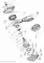
FIG. 1 is an exploded, perspective drawing showing an electrical motor reducer according to the invention and the respective eccentric cam.
FIG. 2 is a cross-section of the motor reducer taken along an axial plane, assembled within the eccentric cam supporting pin.
BEST MODE FOR CARRYING OUT THE INVENTION
With reference to the aforesaid figures, in brief, the motor reducer comprises an electrical motor (1) and an epicyclic reducer (R) housed within a cylindrical casing that serves as supporting pin (2) of an eccentric cam (3).
A pinion (4) of the motor (1) meshes with three planetary gears (5) of the epicyclic reducer (R) which all mesh with a common internal-toothing ring gear (6) fastened inside the pin (2), so that a planetary carrier (7) is forced to rotate in the opposite direction to that of the planetary gears (5) supported by said planetary carrier (7).
A central pinion (7a) of the planetary carrier (7) meshes with a pair of opposed idle gears (8), which rotatably drive the cam (3) that has the structure of a collar exactly fitted on the outside of the supporting pin (2).
On the internal rim of said collar, it is provided an internal-toothing ring gear (3a), which is rotatably driven by said pair of idle gears (8), whose teeth can mesh with those of the gear ring (3a) thanks to the provision of a pair opposed of slots (9) on the cylindrical wall of the hollow pin (2).
As shown in FIG. 2, the pin (2) internally carries two housing compartments (A and B) superimposed to one another and separated by a transversal partition (2a), on which a hole is provided for the passage of the shaft (1a) of, the motor (1), which is housed in the lower compartment (A) while the epicyclic reducer (R) is housed within the upper compartment (B).
The great ease and high accuracy of the assembly of the motor reducer according to the invention consists in that the pin (2) serves as a reference centring for the motor shaft (1), for the fixed ring gear (6) of the epicyclic reducer (R) and for a closing cover plate (10) on which a supporting pin (11) of the pinion (7a) and the opposed pair of pins (12) supporting the opposed pair of idle wheels (8) are provided.
With regard to this, attention is drawn to the fact that on the pin (2) all the circular seats on whose perfect concentricity depends the effective operation of the entire mechanism are machined during the same turning process.
More precisely, the following seats are provided inside the pin (2):
the centring seat (100) of the motor shaft (1a)
the centring seat (101) of the fixed ring gear (6)
the centring seat (102) of the closing cover plate (10).
The cylindrical centring surface (103) of the cam (3) is also made inside the pin (2).
The fact that these circular surfaces are machined during the same turning phase of the pin (2) ensures a perfect reciprocal concentricity and consequently a perfect coupling between all the gears, thus allowing even to assemble the motor (1) separately from the epicyclic reducer (R).
In fact, the motor (1) is inserted and centred in the lower compartment (A), where it is closed by means of a lid (13), while the epicyclic reducer (R) is fitted in the upper compartment (B), where it is closed by the aforesaid cover plate (10).
The perfect coaxiality between the motor (1) and the epicyclic reducer (R) ensures a perfect meshing between the pinion (4) keyed on the motor shaft (1a) and the three planetary gear (5); likewise, the perfect coaxiality between the cover plate (10) and the epicyclic reducer (R) ensures a perfect meshing between the pinion (7a) and the pair of opposed idle gears (8), and, finally, the perfect coaxiality between the cover plate (10) and the external surface (103) of the pin (2) ensures a perfect meshing between the pair of opposed idle gears (8) and internal-toothing ring gear (3a).
As previously mentioned, in the attached figures, it is envisaged that the aforesaid eccentric cam (3) is used in connection with a crank mechanism for transforming a circular motion into a reciprocating straight motion and that said cam (3) oscillates between two limit stop positions, i.e. one idle and one working position, the first reached by effect of the drive of the motor (1) and the other by effect of the return force exerted on the cam (3) by a spring (500).
The solution in which a return spring (500) is adopted instead of reversing the rotation direction of the motor (1) ensures that the working position is always reached, also in the event of a failure of the electrical motor (1).
In this particular type of application, the cam (3) is inserted in the eye (200) of a connecting rod (201) which supports on its other end a pulley (300) to which a reciprocating motion must be conferred to reach an advanced working position and a retracted idle position.
In this embodiment, it is also provided that the pin (2) incorporates a circular boot (2b) adapted to cooperate with a counter-boot (400) to enclose and encompass the eye (200) of the connecting rod (201).
Particularly, said counter-boot (400) surrounds the rim (3b) of said cam (3) on the outside of which an enlarged edge (3c) is provided, which forms a tooth (3d) on which there is fastened the hooked end (600a) of a strap (600) whose other end is provided with a handle (600b).
In practice, the strap (600) is housed within said counter boot (400) and said handle (600b) extends outside a slot (400a) of the counter-boot (400). The strap (600) can be useful during assembly, disassembly or maintenance operations of the apparatus in which said crank mechanism works, whenever it is convenient to stop the pulley (300) in the idle position without using the motor drive (1).
In such circumstances, it will suffice to grasp the handle (600b) and pull the strap (600) to drive the cam (3) against the resistance offered by the return spring (500).
To temporarily stop the strap (600) in maximum extracted position, a lock pin (601) is simply inserted within a special hole (600c) made in the belt itself and within a special hole (400b) made in the counter-boot (400).
Otherwise, lock pin (601) can be rigidly connected on the counter-boot (400), which therefore does not define the special hole (400b) any more.
Claims
1. A cam actuator, comprising a motor (1), an epicyclic reducer (R) driven by said motor (1), a pivot (2) having a hollow structure and housing said motor (1) and said epicyclic reducer (R), and an eccentric cam (3) consisting of a collar inserted on and freely rotatable about said pivot (2) and driven by said epicyclic reducer (R).
2. Cam actuator as claimed in claim 1, characterised in that said epicyclic reducer (R) includes a fixed internal-toothing ring gear (6), a planetary gear carrier (7) having a pinion (7a) and carrying a plurality of planetary gears meshing with said internal-toothing ring gear (6), and at least one idle gear (8) meshing centrally with said pinion (7a) and peripherally with an internal-toothing ring gear (3a) fixed to said eccentric cam (3); and in that said pivot (2) serves as a reference centring for a shaft (1a) of the motor (1), for the fixed internal-toothing ring gear (6) of the epicyclic reducer (R) and for a cover plate (10), which closes a compartment (B) housing the reducer (R) and carries supporting pins (11, 12) for the pinion (7a) of the planetary gear carrier (7) and for said at least one idle gear (8).
3. Cam actuator as claimed in claim 2, characterised in that said epicyclic reducer (R) includes two opposed idle gears (8), said cover plate (10) carrying supporting pins (12) for said idle gears (8).
4. Cam actuator as claimed in claim 3, characterised in that said pivot (2) internally presents the following turned and concentric seats:
a centring seat (100) for said shaft (1a) of said motor (1)
a centring seat (101) for said fixed internal-toothing ring gear (6) of said reducer (R).
a centring seat (102) for said cover plate (10) of said reducer (R).
5. Cam actuator as claimed in claim 4, characterised in that said pivot (2) is defined by an external turned centring surface (103) that cooperates with said cam (3) and is concentric with said centring seats (100, 101 and 102).
6. Cam actuator as claimed in claim 5, characterised in that said pivot (2) internally defines a lower and an upper housing compartments (A, B) separated by a transversal partition (2a), in that said transversal partition (2a) is provided with a hole for the passage of said shaft (1a) of said motor (1), the latter being housed in said lower compartment (A) that is closed by a cover (13), and in that said upper compartment (B) houses said epicyclic reducer (R) and is closed by said cover plate (10).
7. Cam actuator as claimed in claim 6, characterised in comprising a crank mechanism cooperating with said eccentric cam (3) for transforming a circular motion into a reciprocating motion.
8. Cam actuator as claimed in claim 7, characterised in that said cam (3) pivots between one idle position and one working position and is driven in either direction by said motor (1).
9. Cam actuator as claimed in claim 7, characterised in comprising a spring (500) cooperating with said cam (3) and in that said cam (3) pivots between one idle position and one working position, said idle position being reached by effect of the drive of the motor (1) and said working position being maintained by effect of a return force exerted on the claim (3) by said spring (500).
10. Cam actuator as claimed in claim 9, characterised in comprising a circular boot (2b) supporting said pivot (2) and a counter-boot (400) having a slot (400a) and connected with said circular boot (2b), in that said cam (3) defines a rim (3b) surrounded by said counter-boot (400) and having an enlarged edge (3c) carrying a tooth (3d), and in comprising a strap (600) housed inside said counter-boot (400) and having an hooked end (600a) abutting on said tooth (3d), and another end provided with a handle (600b), which is installed outside said slot (400a).
11. Cam actuator as claimed in claim 10, characterised in that said strap (600) carries a hole (600c) for inserting a lock pin (601) to be inserted in another hole (400b) made in the counter-boot (400).
12. Cam actuator as claimed in claim 10, characterised in that said strap (600) carries a hole (600c) for inserting a lock pin (601) which is rigidly connected to said counter-boot (400).
Images & Drawings included:


Sources:
- United States Patent and Trademark Office - verify current appl. status at the USPTO↗
Recent applications in this class:
- » 20250274009 2025-08-28
DIRECT DRIVE GEAR REDUCER MOUNTING SYSTEMS - » 20250266738 2025-08-21
ACTUATOR - » 20250253737 2025-08-07
POWER TRANSMISSION DEVICE - » 20250219505 2025-07-03
RADIALLY STACKED ACTUATOR - » 20250202316 2025-06-19
MODULAR ELECTRIC MOTOR ASSEMBLY - » 20250175057 2025-05-29
HUB DRIVE STRUCTURE - » 20250167629 2025-05-22
DRIVE UNIT - » 20250149953 2025-05-08
VEHICLE DRIVE DEVICE - » 20250141304 2025-05-01
TWO SPEED GEAR REDUCER FOR ELECTRIC DRIVE MODULE - » 20250141303 2025-05-01
ELECTRICAL DRIVE MODULE HAVING MECHANICALLY COUPLED RING GEAR AND CLUTCH BASKET
Recent applications for this Assignee:
- » 20120040789 2012-02-16
Tightener for a belt drive operating in the presence of oil - » 20100222169 2010-09-02
Asymetric damping belt tensioner - » 20090156338 2009-06-18
Pulley assembly for a continuously variable transmission - » 20090105022 2009-04-23
Shoe tensioner for a synchronous belt drive for use with oil - » 20090105021 2009-04-23
Transmission joint pulley assembly - » 20080293527 2008-11-27
Vehicle belt drive torsion bar tensioner with an improved damping device - » 20080287233 2008-11-20
Tightener for a Belt Drive Operating in the Presence of Oil - » 20080196818 2008-08-21
Elastically extensible poly-V transmission belt for driving accessories of an internal combustion engine - » 20080184945 2008-08-07
Actuating device of a recirculation pump for a cooling circuit of an internal combustion engine - » 20070105671 2007-05-10
Pulley for a continuously variable transmission