TOUCH PANEL
US20080185192A1
2008-08-07
11/671,497
2007-02-06
Abstract:
A touch panel has a substrate, a touching layer, an interval frame and a moisture resisting assembly. First and second electric conductive layers are formed respectively on opposite surfaces of the substrate and the touching layer. The interval frame is formed between the substrate and the touching layer to form a space and has an air hole. The moisture resisting assembly is mounted in the air hole to allow air entering the space and prevent moisture entering the space.
Interested in similar patents?
Get notified when new applications in this technology area are published.
Classification:
G06F3/041 » CPC main
Input arrangements for transferring data to be processed into a form capable of being handled by the computer; Output arrangements for transferring data from processing unit to output unit, e.g. interface arrangements; Input arrangements or combined input and output arrangements for interaction between user and computer; Arrangements for converting the position or the displacement of a member into a coded form Digitisers, e.g. for touch screens or touch pads, characterised by the transducing means
G06F3/045 » CPC further
Input arrangements for transferring data to be processed into a form capable of being handled by the computer; Output arrangements for transferring data from processing unit to output unit, e.g. interface arrangements; Input arrangements or combined input and output arrangements for interaction between user and computer; Arrangements for converting the position or the displacement of a member into a coded form; Digitisers, e.g. for touch screens or touch pads, characterised by the transducing means using resistive elements, e.g. a single continuous surface or two parallel surfaces put in contact
G06F3/033 IPC
Input arrangements for transferring data to be processed into a form capable of being handled by the computer; Output arrangements for transferring data from processing unit to output unit, e.g. interface arrangements; Input arrangements or combined input and output arrangements for interaction between user and computer; Arrangements for converting the position or the displacement of a member into a coded form Pointing devices displaced or positioned by the user, e.g. mice, trackballs, pens or joysticks ; Accessories therefor
Description
BACKGROUND OF THE INVENTION
1. Field of the Invention
The present invention relates to a touch panel, and particularly to a touch panel with a moisture resister.
2. Description of the Related Art
The conventional touch panel has a substrate, a touching layer, an interval frame located between the substrate and the touching layer and two ITO (indium-tin oxide) conductive layers. The substrate is made of glass or PET (Polyethylene Terephthalate) and is rectangular. The touching layer is made of PET, and has a shape similar to the substrate. The ITO conductive layers are formed respectively on faces of the substrate and the touching layer.
When the user touches the touching layer, a small deformation is formed, and the touching layer will contact the substrate. Then the ITO conductive layers contact each other and electrically connect to each other to cause the voltage vectors to change. Therefore, the location the user touched is detected, and the conventional touch panel performs the according function.
However, the space between the substrate and the touching layer is airtight so air in the space will expand or contract with the temperature, and deform the touching layer.
Another conventional touch panel has multiple air holes defined in the interval frame to offset the temperature effect. However, the ambient moisture outside will enter the space between the touching layer and the substrate through the air holes and damage the touch panel.
Therefore, the invention provides a touch panel with a moisture resisting assembly to mitigate or obviate the aforementioned problems.
SUMMARY OF THE INVENTION
The main objective of the present invention is to provide a touch panel comprising a substrate, a touching layer, an interval frame and a moisture resisting assembly. First and second electric conductive layers formed respectively on opposite surfaces of the substrate and the touching layer. The interval frame is formed between the substrate and the touching layer to form a space and has an air hole. The moisture resisting assembly is mounted in the air hole to allow air entering the space and prevent moisture entering the space.
Other objectives, advantages and novel features of the invention will become more apparent from the following detailed description when taken in conjunction with the accompanying drawings.
BRIEF DESCRIPTION OF THE DRAWINGS
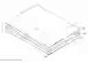
FIG. 1 is an exploded perspective view of a touch panel in accordance with this invention;
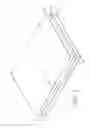
FIG. 2 is a cross-sectional side view of the touch panel in FIG. 1;
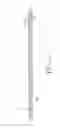
FIG. 3 is an enlarged partial perspective view of the touch panel in FIG. 1 showing an air hole and a first embodiment of a moisture resisting assembly;
FIG. 4 is a side view of the moisture resisting assembly in FIG. 3;
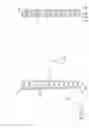
FIG. 5 is an enlarged partial perspective view of the touch panel in FIG. 1 showing the air hole and a second embodiment of a moisture resisting assembly;
FIG. 6 is a side view of the moisture resisting assembly in FIG. 5; and
FIG. 7 is an enlarged partial perspective view of the touch panel in FIG. 1 showing the air hole and a third embodiment of a moisture resisting assembly.
DETAILED DESCRIPTION OF THE PREFERRED EMBODIMENT
With reference to FIGS. 1, 2 and 3, a touch panel in accordance with the present invention has a substrate (10), a touching layer (20), an interval frame (30) and at least one moisture resisting assembly (40).
The substrate (10) is rectangular, is made of glass and has a top face and a first ITO (indium tin oxide) conductive layer (11). The first ITO conductive layer (11) is formed on the top surface of the substrate (10).
The touching layer (20) is rectangular, is made of PET (Polyethylene Terephthalate). The size and shape of the touching layer (20) corresponds to those of the substrate (10). The touching layer (20) has a bottom surface and a second ITO conductive layer (21). The bottom surface of the touching layer (20) faces the top surface of the substrate (10). The second ITO conductive layer (21) is formed on the bottom surface of the touching layer (20) and selectively contacts and selectively electrically connects to the first ITO conductive layer (11).
The interval frame (30) is mounted annularly between the substrate (10) and the touching layer (20) to form a space between the substrate (10) and the touching layer (20) and has a similar size with that of the substrate (10) and the touching layer (20). The interval frame (30) has four edges and at least one air hole (31). Each air hole (31) is formed through one of the four edges of the interval frame (30) to communicate the space with the outside environment and may be a cutout or a through hole.
With further reference to FIGS. 4 to 7, each moisture resisting assembly (40, 50, 60) is mounted in each air hole (31) and may comprise multiple moisture resisting sheets (41), multiple moisture filtering members (51) or multiple moisture resisting sheets (61) and multiple moisture filtering members (62).
With reference to FIGS. 3 and 4, the moisture resisting sheets (41) are stagger arranged. The moisture resisting sheets (41) are insulating, are mounted inside of the air hole (31) and are crisscross to each other. Multiple spaces are formed between the moisture resisting sheets (41) and the inner wall of the air hole (31), so that air can pass through easily. When the air passes through the moisture resisting assembly (40), the moisture remains at the moisture resisting sheets (41), instead of entering to the cavity.
With reference to FIGS. 5 and 6, the moisture filtering members (51) block the moisture and filter the moisture. The shape of the moisture filtering members (51) is irregularity and is adhered to the inner wall of the air hole (31) by some binding agent. The adjacent moisture filtering members (51) are adhered to each other to prevent the moisture. Besides, the moisture filtering members (51) are sintered on the inner wall of the air hole (31), and the adjacent moisture filtering members (51) are also sintered to each other.
With reference to FIG. 7, the moisture resisting sheets (61) and the moisture filtering members (62) are mounted alternatively in the air hole (31). In this embodiment, the moisture filtering members (62) are circular, and located irregularly between the moisture resisting sheets (61) to prevent the moisture.
It is to be understood, however, that even though numerous characteristics and advantages of the present invention have been set forth in the foregoing description, together with details of the structure and function of the invention, the disclosure is illustrative only. Changes may be made in the details, especially in matters of shape, size, and arrangement of parts within the principles of the invention to the full extent indicated by the broad general meaning of the terms in which the appended claims are expressed.
Claims
What is claimed is:1. A touch panel comprising
a substrate having a top surface;
a touching layer having a bottom surface facing to the top surface of the substrate;
a first and second electric conductive layers formed respectively on the top surface of the substrate and the bottom surface of the touching layer;
an interval frame mounted annularly between the substrate and the touching layer to form a space between the substrate and the touching layer and having
four edges; and
at least one air hole, each one of the at least one air hole formed through one of the four edges of the interval frame; and
at least one moisture resisting assembly, each one of the at least one moisture resisting assembly mounted in a corresponding air hole of the interval frame to allow air entering the space and prevent moisture entering the space.
2. The touch panel as claimed in claim 1, wherein each one of the at least one moisture resisting assembly comprises multiple moisture resisting sheets mounted crisscross in the corresponding air hole of the interval frame.
3. The touch panel as claimed in claim 2, wherein the moisture resisting sheets extend into the corresponding air hole of the interval frame.
4. The touch panel as claimed in claim 2, wherein the moisture resisting sheets are insulating.
5. The touch panel as claimed in claim 1, wherein each one of the at least one moisture resisting assembly comprises multiple moisture filtering members.
6. The touch panel as claimed in claim 1, wherein each one of the at least one moisture resisting assembly comprises multiple moisture resisting sheets and multiple moisture filtering members mounted alternatively in the corresponding air hole of the interval frame.
7. The touching control panel claimed in claim 1, wherein each one of the at least one air hole of the interval frame is a cutout.
8. The touching control panel claimed in claim 1, wherein each one of the at least one air hole of the interval frame is a through hole.
9. The touch panel claimed in claim 1, wherein the substrate and the touching layer are rectangular and are similar to each other.
10. The touch panel claimed in claim 9, wherein the interval frame is a rectangular frame.
Images & Drawings included:

Sources:
- United States Patent and Trademark Office - verify current appl. status at the USPTO↗
Similar patent applications:
- » 20230341982
Conductive member for touch panel, touch panel, touch panel display device, and method of producing conductive member for touch panel - » 20180348938
Touch control method for touch panel, touch panel, active stylus for touch panel, and touch display apparatus including touch panel - » 20180364822
Writing sheet for touch panel pen, touch panel, touch panel system, display device, and method for selecting writing sheet for touch panel pen - » 20200183509
Writing sheet for touch panel pen, touch panel, touch panel system, display device, and method for selecting writing sheet for touch panel pen - » 20210173512
Method for selecting touch panel pen writing member, touch panel system, touch panel pen writing member, touch panel, and display device - » 20230376142
Conductive member for touch panel, touch panel, and touch panel display device - » 20160161847
Negative-type photosensitive white composition for touch panel, touch panel and touch panel production method - » 20150167177
Method for fabricating touch panel, touch panel, and electronic device having the touch panel - » 20210247887
Touch panel, touch panel module, and method for inspecting touch panel - » 20210349576
Interdigitatable electrode for touch panel, touch panel including the same, and terminal device with touch panel
Recent applications in this class:
- » 20250156000 2025-05-15
DEVICE WITH A TOUCHSCREEN WHICH COMPRISES A SELF-SUPPORTING PLATE - » 20250155999 2025-05-15
NEXT Hub - » 20250147611 2025-05-08
TOUCH PANEL AND METHOD FOR MANUFACTURING TOUCH PANEL - » 20250130656 2025-04-24
Electronic device - » 20250093984 2025-03-20
DIGITAL JUKEBOX DEVICE WITH IMPROVED USER INTERFACES, AND ASSOCIATED METHODS - » 20250085797 2025-03-13
SENSOR DEVICE - » 20250036225 2025-01-30
DIGITAL JUKEBOX DEVICE WITH IMPROVED USER INTERFACES, AND ASSOCIATED METHODS - » 20240419272 2024-12-19
ELECTRONIC DEVICE - » 20240419271 2024-12-19
TOUCH COMPONENT, TOUCH CHIP, AND TERMINAL DEVICE - » 20240385707 2024-11-21
CONDUCTIVE FILM AND TOUCH SENSOR