Vehicle seat
US20080224511A1
2008-09-18
12/067,496
2006-05-18
✅ Patent granted
US 7,628,453 B2
2009-12-08
WO; PCT/EP2006/004703; 20060518
WO; WO2007/033708; 20070329
Rodney B White
2026-05-18
Abstract:
A vehicle seat, in particular a rear seat bench for a motor vehicle, has a seat part and a backrest which is provided with displaceable side cushions. Their position can be changed as a function of the position of the backrest. According to the invention, at least the backrest is arranged in the vehicle in a manner such that it can be displaced in or counter to the direction of travel, wherein the position of the side cushions located on the outside of the backrest can be forcibly changed as a function of the sliding position of the backrest.
Inventors:
- Marcus Thies 4 🇩🇪 Gevelsberg, Germany
- Guido Herkenrath 2 🇩🇪 Wuppertal, Germany
- Jorg Haubrich 1 🇩🇪 Leverkusen, Germany
Assignee:
- Johnson Controls GmbH 190 🇩🇪 Burscheid, Germany
Interested in similar patents?
Get notified when new applications in this technology area are published.
Classification:
B60N2/99 » CPC main
Seats specially adapted for vehicles; Arrangement or mounting of seats in vehicles; Details or parts not otherwise provided for; Side-rests adjustable
B60N2/0252 » CPC further
Seats specially adapted for vehicles; Arrangement or mounting of seats in vehicles the seat or part thereof being movable, e.g. adjustable; Non-manual adjustment, e.g. with electrical operation with logic circuits with relations between different adjustments, e.g. height of headrest following longitudinal position of seat
B60N2/065 » CPC further
Seats specially adapted for vehicles; Arrangement or mounting of seats in vehicles the seat or part thereof being movable, e.g. adjustable the whole seat being movable slidable Rear seats
B60N2/3022 » CPC further
Seats specially adapted for vehicles; Arrangement or mounting of seats in vehicles for particular purposes or particular vehicles; Non-dismountable or dismountable seats storable in a non-use position, e.g. foldable spare seats back-rest movements by translation only along longitudinal axis
B60N2/3056 » CPC further
Seats specially adapted for vehicles; Arrangement or mounting of seats in vehicles for particular purposes or particular vehicles; Non-dismountable or dismountable seats storable in a non-use position, e.g. foldable spare seats; Cushion movements by translation only along longitunal axis
B60N2/986 » CPC further
Seats specially adapted for vehicles; Arrangement or mounting of seats in vehicles; Details or parts not otherwise provided for Side-rests
B60N2205/35 » CPC further
General mechanical or structural details; Seat or seat parts characterised by comprising plural parts or pieces Seat, bench or back-rests being split laterally in two or more parts
A47C7/14 IPC
Parts, details, or accessories of chairs or stools; Seat parts of adjustable shape; elastically mounted ; adaptable to a user contour or ergonomic seating positions
Description
The invention relates to a vehicle seat, in particular a rear seat bench for a motor vehicle, comprising a seat part and a backrest, which is provided with displaceable side cushions, the position of which can be varied as a function of the position of the backrest.
STATE OF THE ART
A vehicle seat of generic type is disclosed by WO 2004/043207 A2. The backrest of this seat is provided with contoured inserts, which cause the side cushions of the backrest to swivel as a function of their turned position. With the backrest in an upright position of use, the side cushions are shifted forward to produce an especially comfortable support contour for the occupants of the seat. When the backrest is folded forward onto the seat part (loading position) on the other hand, the side cushions are swiveled rearward until the backrest forms a virtually plane support face. This enables the assembly comprising the seat part and the backrest folded forward to be kept especially compact.
OBJECT OF THE INVENTION
The object of the invention is to further develop the vehicle seat of generic type in such a way that the position of the seat occupants can be influenced particularly in the transverse direction (Y-direction) of the vehicle.
SUMMARY OF THE INVENTION
According to the invention the object is achieved in that at least the backrest is arranged in the vehicle so that it is displaceable in or counter to the direction of travel and the position of the side cushions located on the outside of the backrest can be positively varied as a function of the sliding position of the backrest. By shifting the side cushions, the seating position of the occupants in the transverse direction of the seat is influenced without the seat as a whole being displaced in a transverse direction.
The seat part is preferably displaceable together with the backrest, so that the alignment of the side cushions varies as a function of the sliding position of the vehicle seat. The vehicle seat can here advantageously be embodied as a seat bench divided in the transverse direction (Y-direction), the outer segments of the seat bench being provided with displaceable side cushions on their outer side.
According to a first development of the invention the side cushions are capable of swiveling about a vertical axis of the backrest, that is to say about a vertical axis when the backrest is in an upright position of use. Alternatively or in addition, at least the lower part of the side cushions may be rotatable about a transverse axis of the backrest.
It is of particular advantage if, with the backrest in a forward sliding position, the side cushions are swiveled into a position running in the plane of the back support face. In this case, for example, a rear seat bench affords space for three occupants. The side cushions are, in particular, swiveled into their rear position under spring force.
With the backrest in a rear sliding position, on the other hand, the side cushions are swiveled forwards into a support face-contouring position projecting forwards from the back support face, which shifts the seating position of now just two occupants towards the middle in the transverse direction (Y-direction) of the vehicle. This now provides the occupants with an especially comfortable vehicle seat. Swiveling of the side cushions into their forward position preferably ensues due to contact with an actuator fixed to the vehicle body.
DRAWINGS
The drawings are schematic representations of different exemplary embodiments of the invention.
In the drawings:
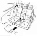
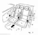
FIG. 1 shows a first inventive, displaceable rear seat bench of a motor vehicle,
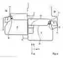
FIG. 2 shows a section through the backrest of the rear seat bench according to FIG. 1, with the seat segments in different sliding positions,
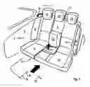
FIG. 3 shows a displaceable rear seat bench according to another embodiment of the invention.
The rear seat bench 1 according to FIG. 1 comprises a seat part 2 and a backrest 3 affixed thereto and is asymmetrically divided in a transverse direction (Y-direction of the vehicle) into two segments 4, 4′, which are independently anchored in the vehicle body so that they are displaceable in or counter to the direction of travel (−X or X-direction of the vehicle. On its outside, that is to say on the areas of the segments 4, 4′ facing the vehicle body side walls 5, the backrest 3 has swiveling side cushions 6, 6′, which are rotatable about a vertical axis 7 of the backrest 3 in the direction of the arrow A. The vertical axis 7, 7′ extends approximately vertically when the backrest 3 is in the upright position of use. This does not preclude a facility for folding the actual backrest 3 into some other position, in order to increase the load capacity of the trunk, for example.
As can be seen from the section according to FIG. 2, the side cushion 6′ of the segment 4′ is held back by a spring 8′ about the vertical axis 7′ in a position in which it runs approximately flush with the support face 9 of the backrest 3. If the rear seat bench is shifted in the X-direction from a forward sliding position (segment 4′) into a rear sliding position (segment 4), the associated side cushion 6 strikes the wheel arch 10 of the vehicle body (or other actuators arranged there), and is positively swiveled forward about the vertical axis 7 under the compression of the spring 8. The position of the seat occupants is thereby shifted in the transverse direction (Y-direction) towards the middle of the vehicle.
If the rear seat bench as a whole is located in a forward sliding position, it can accommodate three occupants. After sliding both segments 4, 4′ back, on the other hand, there is only space available for two persons, who will nevertheless enjoy a more comfortably contoured backrest 3. The contour is supplemented by a middle cushion 11 that folds out of the seat part 2.
In the case of the rear seat bench according to FIG. 3, the side cushions 6, 6′ are each divided into an upper, rigid part 12, 12′ and lower, rotating part 13, 13′. The lower parts 13, 13′ are capable of swiveling about a transverse axis 14 of the backrest 3 and under the action of a spring (not shown) are held in a rear plane running flush with the support face of the backrest 3 when the rear seat bench 1 is pushed forward. When the rear seat bench 1 is pushed back, the lower parts 13, 13′ strike the wheel arches 10 or other actuators fixed to the vehicle body and are thereby shifted forwards (arrows B). This also serves to adjust the seating position in the desired way. Armrests 15 folding out of the center of the backrest complete the comfort afforded.
The head restraints 16, 16′ of the rear seat benches according to FIGS. 1 to 3 are so wide that they afford protection for the relevant number of occupants in all predefined seating positions, only the outer head restraints 16 serving for head support when the rear seat bench 1 is pushed back.
The side cushions 6, 6′ need not necessarily be adjusted by the mechanical means described. Instead adjustment may be performed pneumatically, hydraulically or electrically through detection of the sliding position adjustment of the rear seat bench 1. It is likewise possible to combine the positive adjustments of the side cushions 6, 6′ previously described with one another and for the parts 12, 13 and 12′, 13′ each to swivel about the vertical axes 7, 7′ and for the lower parts 13, 13′ again to swivel about the transverse axis 14.
LIST OF REFERENCE NUMERALS
- 1 rear seat bench
- 2 seat part
- 3 backrest
- 4, 4′ segment
- 5 vehicle body wall
- 6, 6′ side cushion
- 7, 7′ vertical axis
- 8, 8′ spring
- 9 support face
- 10 wheel arch
- 11 middle cushion
- 12 upper part (of the side cushion)
- 13 lower part (of the side cushion)
- 14 transverse axis
- 15 arm rests
- 16, 16′ head restraint
Claims
1. A vehicle seat, in particular a rear seat bench for a motor vehicle, comprising a seat part and a backrest, which is provided with displaceable side cushions, the position of which can be varied as a function of the position of the backrest, wherein at least the backrest is arranged in the vehicle so that it is displaceable in or counter to the direction of travel and the position of the side cushions located on the outside of the backrest can be positively varied as a function of the sliding position of the backrest.
2. The vehicle seat as claimed in claim 1, wherein the seat part is displaceable together with the backrest.
3. The vehicle seat as claimed in claim 1, wherein the vehicle seat is embodied as a seat bench divided in the transverse direction, the outer segments of the seat bench being provided with displaceable side cushions on their outer side.
4. The vehicle seat as claimed in claim 1, wherein the side cushions are capable of swiveling about a vertical axis of the backrest.
5. The vehicle seat as claimed in claim 1, wherein at least the lower part of the side cushions is rotatable about the transverse axis of the backrest.
6. The vehicle seat as claimed in claim 5, wherein when the backrest is in a forward sliding position, the side cushions are swiveled into a position running in the plane of the support face for the backs of the seat occupants.
7. The vehicle seat as claimed in claim 6, wherein the side cushions are swiveled into their rear position under the action of a spring.
8. The vehicle seat as claimed in claim 6, wherein when the backrest is in a rear sliding position the side cushions are swiveled forwards into a position projecting forwards from the support face.
9. The vehicle seat as claimed in claim 8, wherein the side cushions are swiveled into their forward position due to contact with an actuator fixed to the vehicle body, in particular contact with the wheel arches.
Images & Drawings included:
Sources:
- United States Patent and Trademark Office - verify current appl. status at the USPTO↗
Similar patent applications:
- » 20130328370
Adjusting device for a vehicle seat, vehicle seat, row of seats,vehicle seat and method for this - » 20180072192
Height adjusting mechanism for a vehicle seat, in particular a utility vehicle seat, and vehicle seat, in particular utility vehicle seat - » 20230273364
FLEXIBLE FABRIC FOR AN INTERIOR OF A VEHICLE, SEAT COVER FOR A VEHICLE SEAT, VEHICLE SEAT AND VEHICLE - » 20200055429
FLEXIBLE FABRIC FOR THE INTERIOR OF A VEHICLE, SEAT COVER FOR A VEHICLE SEAT, VEHICLE SEAT AND VEHICLE - » 20070013204
Vehicle seat, vehicle seat storage structure and vehicle seat structure - » 20210101512
Vehicle seat, vehicle seat control device, and vehicle seat control method - » 20080157579
Vehicle seat, vehicle seat storage structure and vehicle seat structure - » 20190077289
MASSAGE DEVICE FOR A VEHICLE SEAT, VEHICLE SEAT, AND METHOD FOR PRODUCING A VEHICLE SEAT - » 20130187423
ADJUSTMENT DEVICE FOR ADJUSTING A MOTOR VEHICLE SEAT, MOTOR VEHICLE SEAT, MOTOR VEHICLE AND METHOD FOR ADJUSTING A MOTOR VEHICLE SEAT - » 20140028070
ADJUSTING DEVICE FOR ADJUSTING A MOTOR VEHICLE SEAT, MOTOR VEHICLE SEAT, MOTOR VEHICLE AND METHOD FOR ADJUSTING A MOTOR VEHICLE SEAT
Recent applications in this class:
- » 20250187513 2025-06-12
VEHICLE SEAT - » 20240270142 2024-08-15
Vehicle seat - » 20240083318 2024-03-14
Vehicle including a seat having reconfigurable bolsters - » 20230147969 2023-05-11
Vehicle seat - » 20230018645 2023-01-19
Seat side bolster apparatus and control method thereof - » 20220314857 2022-10-06
Actuator for a support system of a seat - » 20220305976 2022-09-29
Adjustment mechanism for seating assembly member - » 20210245643 2021-08-12
Pneumatic adjusting device for a side wing of a vehicle seat - » 20210245642 2021-08-12
Side bolster adjustment apparatus, side bolster adjustment system, and side bolster adjustment method for vehicle seat - » 20200391640 2020-12-17
VEHICLE SEAT
Recent applications for this Assignee:
- » 20180154800 2018-06-07
Vehicle seat having an adjusting device - » 20170028887 2017-02-02
Method for producing an element having a cover, and such an element - » 20160318428 2016-11-03
Foam part, in particular for a vehicle seat, and vehicle seat - » 20160311008 2016-10-27
Method for connecting a first component to a second component by plastic deformation - » 20160311007 2016-10-27
Method for connecting a first component to a second component - » 20160297330 2016-10-13
Vehicle seat with a recliner - » 20160243966 2016-08-25
Vehicle seat, in particular motor vehicle seat - » 20160236591 2016-08-18
METHOD FOR PRESETTING A VEHICLE SEAT - » 20160229318 2016-08-11
Locking unit for a vehicle seat, and vehicle seat - » 20160221474 2016-08-04
Method for adjusting a vehicle seat and system for adjusting a vehicle seat