Light modules
US20080225533A1
2008-09-18
11/747,767
2007-05-11
✅ Patent granted
US 7,427,148 B1
2008-09-23
-
-
Hargobind S Sawhney
2027-05-11
Abstract:
Light modules are provided. A light module includes a circuit board, a lighting element electrically connected to the circuit board, and a first thermal plate. The circuit board has a through hole communicating a first side and a second side thereof. The lighting element is disposed on the first side of the circuit board and located corresponding to the through hole. The first thermal plate is disposed on the second side of the circuit board, opposite to the first side, and comprises a first protrusion extending through the through hole and connecting the lighting element.
Inventors:
- Tien-Fu Huang 14 🇹🇼 Hsinchu County, Taiwan
- Shih-Hao Hua 5 🇹🇼 Changhua County, Taiwan
- CHIN YIN YU 3 🇹🇼 YILAN COUNTY, Taiwan
- Kuo-Chang Hu 2 🇹🇼 Miaoli County, Taiwan
- Shyh-Rong Tzan 2 🇹🇼 Hsinchu County, Taiwan
Assignee:
- INDUSTRIAL TECHNOLOGY RESEARCH INSTITUTE 7,890 🇹🇼 HSINCHU, Taiwan
Interested in similar patents?
Get notified when new applications in this technology area are published.
Classification:
F21V29/71 » CPC main
Protecting lighting devices from thermal damage; Cooling or heating arrangements specially adapted for lighting devices or systems; Cooling arrangements characterised by passive heat-dissipating elements, e.g. heat-sinks using a combination of separate elements interconnected by heat-conducting means, e.g. with heat pipes or thermally conductive bars between separate heat-sink elements
F21K9/00 » CPC further
Light sources using semiconductor devices as light-generating elements, e.g. using light-emitting diodes [LED] or lasers
F21V19/004 » CPC further
Fastening of light sources or lamp holders the light sources being semiconductors devices, e.g. LEDs; Fastening of light source holders, e.g. of circuit boards or substrates holding light sources by deformation of parts or snap action mountings, e.g. using clips
F21V29/70 » CPC further
Protecting lighting devices from thermal damage; Cooling or heating arrangements specially adapted for lighting devices or systems; Cooling arrangements characterised by passive heat-dissipating elements, e.g. heat-sinks
F21V29/83 » CPC further
Protecting lighting devices from thermal damage; Cooling or heating arrangements specially adapted for lighting devices or systems; Cooling arrangements characterised by passive heat-dissipating elements, e.g. heat-sinks the elements having apertures, ducts or channels, e.g. heat radiation holes
H05K1/0204 » CPC further
Printed circuits; Details; Thermal arrangements, e.g. for cooling, heating or preventing overheating; Cooling of mounted components using means for thermal conduction connection in the thickness direction of the substrate
H05K1/0204 » CPC further
Printed circuits; Details; Thermal arrangements, e.g. for cooling, heating or preventing overheating; Cooling of mounted components using means for thermal conduction connection in the thickness direction of the substrate
F21Y2105/10 » CPC further
comprising a two-dimensional array of point-like light-generating elements
F21Y2115/10 » CPC further
Light-generating elements of semiconductor light sources Light-emitting diodes [LED]
H05K3/0061 » CPC further
Apparatus or processes for manufacturing printed circuits; Laminating printed circuit boards onto other substrates, e.g. metallic substrates onto a metallic substrate, e.g. a heat sink
H05K3/0061 » CPC further
Apparatus or processes for manufacturing printed circuits; Laminating printed circuit boards onto other substrates, e.g. metallic substrates onto a metallic substrate, e.g. a heat sink
H05K2201/0382 » CPC further
Indexing scheme relating to printed circuits covered by; Conductive materials; Structure of the conductor; Conductor shape Continuously deformed conductors
H05K2201/0382 » CPC further
Indexing scheme relating to printed circuits covered by; Conductive materials; Structure of the conductor; Conductor shape Continuously deformed conductors
H05K2201/10106 » CPC further
Indexing scheme relating to printed circuits covered by; Details of components or other objects attached to or integrated in a printed circuit board; Types of components Light emitting diode [LED]
H05K2201/10106 » CPC further
Indexing scheme relating to printed circuits covered by; Details of components or other objects attached to or integrated in a printed circuit board; Types of components Light emitting diode [LED]
F21V29/00 IPC
Protecting lighting devices from thermal damage; Cooling or heating arrangements specially adapted for lighting devices or systems
Description
BACKGROUND OF THE INVENTION
1. Field of the Invention
The invention relates in general to light modules and in particular to light modules with high heat dissipation efficiency.
2. Description of the Related Art
With the progress of semiconductor and electronic technologies, traditional Cathode Ray Tube (CRT) displays have increasingly been replaced by flat panel displays having small size and low radiation. Generally, conventional flat panel displays use Cold Cathode Fluorescent Lamps (CCFL) as backlight. However, CCFLs provide only a short lifetime and present difficulties when facilitating miniaturization.
As a result of the aforementioned disadvantages, LEDs have been increasingly applied rather than the conventional CCFL as a light source for the flat panel display. Specifically, since excessive high temperature can adversely reduce illumination and lifetime of LEDs, heat dissipation becomes critical.
BRIEF SUMMARY OF THE INVENTION
Light modules are provided. A light module includes a circuit board, a lighting element electrically connected to the circuit board, and a first thermal plate. The circuit board has a through hole communicating a first side and a second side thereof. The lighting element is disposed on the first side of the circuit board and located corresponding to the through hole. The first thermal plate is disposed on the second side of the circuit board, opposite to the first side, and comprises a first protrusion extending through the through hole and connecting the lighting element.
BRIEF DESCRIPTION OF THE DRAWINGS
The invention can be more fully understood by reading the subsequent detailed description and examples with references made to the accompanying drawings, wherein:
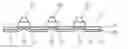
FIG. 1 is a sectional view of a light module;
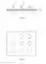
FIG. 2 is a perspective diagram of the circuit board shown in FIG. 1; and
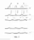
FIG. 3 is a sectional view of another embodiment of a light module.
DETAILED DESCRIPTION OF THE INVENTION
Referring to FIG. 1, an embodiment of a light module for an electronic device, such as a backlight of a flat panel display, primarily comprises a circuit board 10, a plurality of lighting elements 20 electrically connected to the circuit board 10, and a first thermal plate 30. In this embodiment, the circuit board 10 is a FR-4 printed circuit board, and the lighting elements 20 are LEDs. The first thermal plate 30 has higher thermal conductivity than the circuit board 10, such as an aluminum plate.
As shown in FIG. 1, the lighting elements 20 are disposed on a first side 11 of the circuit board 10, and the first thermal plate 30 is disposed on a second side 12 of the circuit board 10, opposite to the first side 11, to dissipate heat from the lighting elements 20. The circuit board 10 and the first thermal plate 30 can be directly secured by screws or mechanically interlocked with each other. However, the circuit board 10 and the first thermal plate 30 can also be connected to each other by an adhesive thermal pad (not shown) disposed therebetween.
In this embodiment, the circuit board 10 has a plurality of through holes 13 communicating with the first and second sides 11 and 12, and correspondingly, the first thermal plate 30 has a plurality of first protrusions 31 projecting toward the lighting elements 20 via the through holes 13. As shown in FIG. 1, the first protrusions 31 extend through the through holes 13 and physically contact the lighting elements 20, such that heat from the lighting elements 20 is rapidly transferred downward and dissipated via the first thermal plate 30. In some embodiments, the first protrusion 31 and the lighting element 20 can also be thermally connected via an electrically insulating thermal pad (not shown) disposed therebetween.
Referring to FIG. 2, an embodiment of the lighting elements 20 and the through holes 13 of the first thermal plate 30 are arranged in matrix to provide uniform illumination. However, they can also be arranged in other specific formations to meet illumination distribution requirements.
As shown in FIG. 3, another embodiment of a light module comprises a circuit board 10, a plurality of lighting elements 20 disposed on a first side 11 of the circuit board 10, a first thermal plate 30 disposed on a second side 12 of the circuit board 10, and at least a second thermal plate 40 below the first thermal plate 30. In this embodiment, the first thermal plate 30 has a plurality of first protrusions 31 extending through the through holes 13 of the circuit board 10 and contacting the lighting elements 20. The second thermal plate 40 has a plurality of second protrusions 41 projecting toward the circuit board 10 and connecting the first thermal plate 30. Specifically, locations of the second protrusions 41 are offset with respect to the first protrusions 31, such that the first and second thermal plates 30 and 40 form a space therebetween, increasing heat dissipation area and cooling efficiency thereof. Furthermore, the light module may comprise more thermal plates below the first and second thermal plates 30 and 40, such as the thermal plates 50 and 60 shown in FIG. 3, to enhance cooling efficiency thereof.
Light modules are provided according to the embodiments. A light module comprises a circuit board, a lighting element disposed on a first side of the circuit board, and a thermal plate disposed on a second side of the circuit board, opposite to the first side. The circuit board has at least one through hole with a protrusion of a thermal plate extending therethrough, wherein the protrusion connects the lighting element to dissipate heat via the thermal plate, preventing failure of the lighting element or circuit board due to high temperature.
While the invention has been described by way of example and in terms of preferred embodiment, it is to be understood that the invention is not limited thereto. To the contrary, it is intended to cover various modifications and similar arrangements (as would be apparent to those skilled in the art). Therefore, the scope of the appended claims should be accorded the broadest interpretation to encompass all such modifications and similar arrangements.
Claims
1. A light module, comprising:
a circuit board, comprising a first side, a second side opposite to first side, and a through hole communicating with the first and second sides;
a lighting element, electrically connected to the circuit board and disposed on the first side, corresponding to the through hole;-and
a first thermal plate, disposed on the second side of the circuit board, comprising a first protrusion extending through the through hole and connecting the lighting and
a second thermal plate connected to the first thermal plate, wherein the second thermal plate comprises a second protrusion projecting toward the circuit board and connecting the first thermal plate.
2. The light module as claimed in claim 1, wherein the first thermal plate has higher thermal conductivity than the circuit board.
3. The light module as claimed in claim 1, wherein the lighting element comprises an LED.
4. The light module as claimed in claim 1, wherein the circuit board is a FR-4 printed circuit board.
5. The light module as claimed in claim 1, further comprising a plurality of lighting elements, the circuit board further comprising a plurality of through holes corresponding to the lighting elements, the first thermal plate further comprising a plurality of first protrusions respectively extending through the through hole and connecting the lighting elements.
6. The light module as claimed in claim 5, wherein the lighting elements and the through holes are arranged in matrix.
7-8. (canceled)
9. The light module as claimed in claim 1, wherein location of the second protrusion is offset with respect to the first protrusion.
10. The light module as claimed in claim 9, wherein the first and second thermal plates form a space therebetween.
Images & Drawings included:
Sources:
- United States Patent and Trademark Office - verify current appl. status at the USPTO↗
Similar patent applications:
- » 20070211458
Light module, light multiple module and use of a light module or light multiple module for illumination or backlighting - » 20120206917
Lighting module, lighting device comprising a lighting module, method for assembling a lighting module and method for assembly of a lighting device - » 20190025686
METHOD FOR PRODUCING A LIGHT MODULE, LIGHT MODULE AND METHOD FOR OPERATING A LIGHT MODULE AND COMPUTER PROGRAM PRODUCT - » 20210048692
Spatial light modulator, light modulating device, and method for driving spatial light modulator - » 20240004225
Spatial light modulator, light modulating device, and method for driving spatial light modulator - » 20150185523
LIGHT MODULATION METHOD, LIGHT MODULATION PROGRAM, LIGHT MODULATION DEVICE, AND ILLUMINATION DEVICE - » 20220236599
Manufacturing method of light modulation panel, light modulation panel and light modulation device - » 20240369199
Lighting system for emitting light comprising two connectable lighting modules, a lighting module, a method of operating a lighting module as well as a corresponding method - » 20110095242
Thermochromic microparticles, dispersions thereof, and manufacturing method thereof, as well as light-modulating coatings, light-modulating films and light-modulating inks - » 20190292444
Light-modulating material, light-modulating film, and light-modulating laminate
Recent applications in this class:
- » 20230245880 2023-08-03
LIGHT IRRADIATION DEVICE - » 20220412546 2022-12-29
HEAT DISSIPATION DEVICE FOR LED LIGHT STRIP OF TELEVISION - » 20220178533 2022-06-09
Light source device, cooling method, and manufacturing method for product - » 20210164642 2021-06-03
Light source device - » 20210131657 2021-05-06
Internal-circulating heat dissipation system for stage light - » 20210123592 2021-04-29
HIGH MAST LUMINAIRE WITH COOLING CHANNELS - » 20210025582 2021-01-28
Lamp - » 20200088396 2020-03-19
Solid state lighting lamp - » 20190368719 2019-12-05
LAMP DEVICE - » 20170159925 2017-06-08
Low profile light and accessory kit for the same
Recent applications for this Assignee:
- » 20250289330 2025-09-18
MOBILE VEHICLE CHARGING PROTECTION DEVICE FOR ELECTRICAL SAFETY IN LIVESTOCK HOUSES - » 20250287224 2025-09-11
COMMUNICATION DEVICE AND COMMUNICATION METHOD - » 20250286593 2025-09-11
COMMUNICATION DEVICE AND METHOD OF BEAM MANAGEMENT - » 20250284336 2025-09-11
SYSTEM AND METHOD FOR ADJUSTING IMAGE BASED ON PHYSIOLOGICAL INFORMATION AND POSTURE - » 20250281908 2025-09-11
ELECTROCATALYST COMPOSITION AND PREPARATION METHOD THEREOF - » 20250273403 2025-08-28
CAPACITOR AND ELECTRONIC DEVICE - » 20250271759 2025-08-28
POLYMER, POSITIVE PHOTORESIST COMPOSITION, AND METHOD FOR FORMING PATTERNED PHOTORESIST LAYER - » 20250265803 2025-08-21
MULTI-SENSOR COORDINATION METHOD, PROCESSING DEVICE, AND INFORMATION DISPLAY SYSTEM - » 20250263659 2025-08-21
METHOD AND KIT FOR PREPARING AN IMMUNE CELL DIFFERENTIATED FROM A STEM CELL - » 20250252547 2025-08-07
CORROSION POSITIONING SYSTEM, CORROSION INSPECTION VEHICLE AND CORROSION POSITIONING METHOD USING THE SAME