Projector lamp having pulsed monochromatic microwave light sources
US20080245976A1
2008-10-09
12/062,834
2008-04-04
✅ Patent granted
US 7,954,955 B2
2011-06-07
-
-
Haissa Philogene
2029-11-19
Abstract:
A light engine for image display projectors has a plurality of monochromatic light sources, typically red, blue and green, combined into one light generation device powered by microwaves pulsed at 3-5 KHz rates. The light engine has a microwave power supply, microwave coupling cavity, a microwave coupler coupling a microwave signal from the microwave power supply to the microwave coupling cavity, and the plurality of monochromatic light sources disposed in the microwave coupling cavity and powered by the microwave signal. The microwave coupling cavity includes a plurality of resonance points, each of the monochromatic light sources being located respectively at one of the resonance points.
Inventors:
- Bernard John Eastlund 2 🇺🇸 Saint Louis, MO, United States
- Sherrie R. Eastlund 1 🇺🇸 St. Louis, MO, United States
Interested in similar patents?
Get notified when new applications in this technology area are published.
Classification:
G02B21/36 IPC
Microscopes arranged for photographic purposes or projection purposes or digital imaging or video purposes including associated control and data processing arrangements
G03B21/2006 » CPC main
Projectors or projection-type viewers; Accessories therefor; Details; Lamp housings characterised by the light source
H01J61/94 » CPC further
Gas-discharge or vapour-discharge lamps; Lamps with more than one main discharge path Paths producing light of different wavelengths, e.g. for simulating daylight
H01J65/044 » CPC further
Lamps without any electrode inside the vessel; Lamps with at least one main electrode outside the vessel; Lamps in which a gas filling is excited to luminesce by an external electromagnetic field or by external corpuscular radiation, e.g. for indicating plasma display panels by an external electromagnetic field the field being produced by a separate microwave unit
H04N9/3161 » CPC further
Details of colour television systems; Picture reproducers; Projection devices for colour picture display, e.g. using electronic spatial light modulators [ESLM]; Constructional details thereof; Modulator illumination systems using laser light sources
H04N9/3164 » CPC further
Details of colour television systems; Picture reproducers; Projection devices for colour picture display, e.g. using electronic spatial light modulators [ESLM]; Constructional details thereof; Modulator illumination systems using multiple light sources
A61N5/06 IPC
Radiation therapy using light
Description
This application claims the benefit of the priority date of U.S. Provisional Patent Application No. 60/921,791, which was filed on Apr. 4, 2007, and which is hereby incorporated herein by reference.
BACKGROUND OF THE INVENTION—FIELD OF INVENTION
This invention generally relates to light engines for image display projectors
BACKGROUND OF THE INVENTION—PRIOR ART
The separation of light into usable colors is a critical function incorporated into projector light engines. Various technologies, such as the sequential color wheels, prism systems, etc., have been developed for such separation of colors from full visible spectrum or “white” light. Color wheels are particular to reflective image generation devices (“imagers”) such as DLP manufactured by Texas Instruments Corp. and may also used in some LCOS systems available from various suppliers. The light source for projection systems is generally broad spectrum (“white light”) sources such as high intensity discharge (“HID”) lamps manufactured by Philips and others. These lamps are typically use 75 to 150 watts power and provide adequate light for projection but are generally inefficient, light quality degrades over time, extensive cooling is required and HID lamps have lifetime limitations. An emerging technology is the use of light emitting diodes (“LED”), which are solid-state laser light sources. They can be monochromatic and can be pulsed. Table 1 is a description of typical design requirements for an LED light source as incorporated into a light engine. Ideally at least three separate, monochromatic LED's, usually in red, blue and green, would be used. Each respective color is turned on and off at a frequency of 3 to 5 KHz. LED light sources are limited by the total lumens generated per color and the relatively large size of the emitting region (etendue) required. LED's can be long lived but are generally low efficiency and generate significant beat that must be removed.
| TABLE 1 |
| CURRENT DESIGN TARGETS FOR LED LIGHT SOURCES |
| Parameter | Target | Comments | 2/07 Add'l Comments CD |
| Total Flux | (180° Output) | Assume duty cycle <60% | Very dependent on source |
| Brightness | Red: ~425 average | per color that may be | etendue, imager size, screen |
| lumens | adjusted randomly. | size and gain. Imager is | |
| Green: ~1500 average | Assuming >70% | currently 0.65″ diagonal | |
| lumens | collected in 60 | moving to 0.45″ diagonal in | |
| Blue: ~130 average | degree cone | size. Ultimate target is | |
| lumens | 1000 nits on screen with 2× | ||
| gain. | |||
| LED | ~12 mm{circumflex over ( )}2 for 0.65″ | Imaged onto a 16:9 device | |
| Emitting | imager | illuminated at ~28° at | |
| Area | approx. f/2.0 × f/2.4 | ||
| Junction to | □ 1 C/W | Total heat dissipation | |
| Case | capability of system | ||
| Thermal | heatsink solution is | ||
| Resistance | typically ~.5 C/W during | ||
| operation | |||
| Operating | 2-5 KHz | Typical pulsing rate during | With color sequential |
| Frequency | operation (per color) | system, switching speed 10 | |
| is ~2800 Hz. | uS (full off to full on) and | ||
| pulse periods down to 400 | |||
| uS. | |||
| Operating | 1%-60% | May be adjusted randomly | Per color per frame |
| Duty Cycle | (per color) | ||
| Variability | |||
| Operating | 10-45 C. | Typical conditions - varies | |
| Ambient | by OEM product design | ||
| Temperature | requirements | ||
| Range | |||
| Operating | Minimum: 20,000 Hrs | Target 60K hours as | |
| Lifetime | Typical: 60,000 Hrs | minimum | |
| Operating | 0%-100% | Operating current may vary | |
| Current | randomly - Ohmic | ||
| Variability | Resistance must be low | ||
| enough to support stable | |||
| turn on at low current levels | |||
| Die | Rotation: TBD | ||
| placement | X/Y: TBD | ||
| tolerance to | |||
| package | |||
| alignment | |||
| features | |||
| Target | Red: ~620-630 nm | Nominal Output | |
| Output | Green: ~520-540 nm | Wavelengths (per color) | |
| Wavelengths | Blue: ~455-465 nm | utilizing the best | |
| combination of wavelength, | |||
| duty cycle, and intensity for | |||
| maximum brightness | |||
BACKGROUND OF THE INVENTION—OBJECTIVES
This invention is a method and apparatus for producing a light engine with three separate monochromatic light sources, typically red, blue and green, combined into one light generation device powered by microwaves pulsed at 3-5 KHz rates. The individual light sources are cylindrical or spherical in shape with internal dimensions in any direction generally less than 0.6 mm. They would generally generate power densities exceeding 15,000 watt/cm3.
SUMMARY
The principal claim is a light engine with three separate, microwave powered, pulsed, monochromatic light sources, typically one each in red, green and blue. The light sources are lamps that contain selected light generating materials in a background inert gas contained within sapphire or quartz envelopes.
Another principal claim is a new light source, which is microwave powered, pulsed, and either broad spectrum or monochromatic, with applications for light generation in image display projection system, medical or other industrial uses.
Another principal claim is a microwave powered light engine incorporating three separate monochromatic lamps, with a waveguide coupling structure that has three spatially separated resonance locations, and a power supply that can be controlled to adjust the phase of the microwaves by means of an electronic digital phase shifter used to sequentially shift the phase of the microwaves in order to concentrate the power at the three spatially separated resonance locations corresponding to the location of the lamps. Another principal claim is a sapphire envelope lamp with a fill of ZnCl2, or ZnBr2 and Xenon to produce emission primarily in the red spectrum between 620 and 630 nm. It may include a blocking filter to transmit only the radiation within the 620 to 630 nm band.
Another principal claim is a sapphire envelope lamp with a fill of ThCl2, or ThBr2 and Xenon to produce emission primarily in the green spectrum between 520 and 540 nm. It may include a blocking filter to transmit only the radiation within the 520 to 540 nm band.
Another principal claim is a sapphire envelope lamp with a fill of InCl2, or InBr2 and Xenon to produce emission primarily in the blue spectrum between 455 and 465 nm. It may include a blocking filter to transmit only the radiation within the 455 to 465 nm band.
A summary comparison of this new light source with the LED specifications above is as follows:
| TABLE 2 |
| TRICOLOR MICROWAVE LAMP DESIGN VERSUS LED REQUIREMENTS |
| Parameter | Target | Comments | GEM Lamp Performance |
| Total Flux | (180° Output) | Assume duty cycle <60% | Maximum dimension is |
| Brightness | Red: ~425 average | per color that may be | 0.6 mm in major dimension |
| lumens | adjusted randomly. | in order to better etendue | |
| Green: ~1500 average | Assuming >70% | match with imagers 0.65″ or | |
| lumens | collected in 60 | less in diagonal. | |
| Blue : ~130 average | degree cone | Red~1000 average lumens | |
| lumens | Green~10,000 average | ||
| lumens | |||
| Blue~2500 average lumens | |||
| (More if desired) | |||
| LED | ~12 mm{circumflex over ( )}2 for 0.65″ | Imaged onto a 16:9 device | Emitting area about 0.36 |
| Emitting | imager | illuminated at ~28° at | mm2 |
| Area | approx. f/2.0 × f/2.4 | ||
| Junction to | □ 1 C/W | Total heat dissipation | N/A |
| Case | capability of system | Total power input is about | |
| Thermal | heatsink solution is | 40 watts to generate lumens | |
| Resistance | typically ~.5 C/W during | indicated above. | |
| operation | |||
| Operating | 2-5 KHz | Typical pulsing rate during | Three separate color sources |
| Frequency | operation (per color) | with a 3-15 KHz switching | |
| is ~2800 Hz. | capability with 10 μS from | ||
| full off to full on with | |||
| arbitrary off periods. | |||
| Operating | 1%-60% | May be adjusted randomly | Arbitrary duty cycle |
| Duty Cycle | (per color) | possible | |
| Variability | |||
| Operating | 10-45 C. | Typical conditions - varies | 10-45 C. |
| Ambient | by OEM product design | ||
| Temperature | requirements | ||
| Range | |||
| Operating | Minimum: 20,000 Hrs | Target 60K hours as | 20,000 to 60,000 Hrs, |
| Lifetime | Typical: 60,000 Hrs | minimum | higher end of range with |
| sapphire envelope lamps. | |||
| Operating | 0%-100% | Operating current may vary | No such limitation |
| Current | randomly - Ohmic | ||
| Variability | Resistance must be low | ||
| enough to support stable | |||
| turn on at low current levels | |||
| Die | Rotation: TBD | N/A | |
| placement | X/Y: TBD | ||
| tolerance to | |||
| package | |||
| alignment | |||
| features | |||
| Target | Red: ~620-630 nm | Nominal Output | Red ~620-630 nm |
| Output | Green: ~520-540 nm | Wavelengths (per color) | Green ~520-540 nm |
| Wavelengths | Blue: ~455-465 nm | utilizing the best | Blue ~455-465 nm |
| combination of wavelength, | |||
| duty cycle, and intensity for | |||
| maximum brightness | |||
BRIEF DESCRIPTION OF THE DRAWINGS
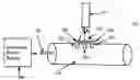
FIG. 1 illustrates a tricolor microwave lamp engine system, according to an embodiment of the present invention.
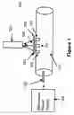
FIG. 2 illustrates FIG. 2 illustrates how the position of the resonance changes with time, according to an embodiment of the present invention.
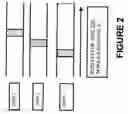
FIG. 3 illustrates a microwave power supply, according to an embodiment of the present invention.
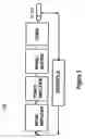
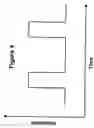
FIG. 4 illustrates a microwave pulse as a function of time, according to an embodiment of the present invention.
DESCRIPTION
The Tricolor Microwave Lamp light Engine comprises, for example, the following components:
- 1. Three separate lamps that use single crystal sapphire or quartz envelopes:
- One lamp which emits light in the red spectrum, between 620 and 630 nm with a fill of one or more of ZnCl2 or ZnBr2 and one or more of Argon or Xenon background gases.
- One bulb which emits light in the green spectrum, between 420 and 540 nm with a fill of one or more of TlCl2 or TlBr2 and one or more of Argon and Xenon background gases.
- One bulb which emits light in the blue spectrum, between 455 and 465 nm with a fill of one or more of InCl2 or InBr2 and one or more of Argon and Xenon background gases.
- 2. A microwave coupling cavity with three separate resonance positions that are determined by the geometry of the resonance cavity and the phase of the microwaves within the cavity.
- 3. A microwave power supply that can be pulsed in time and changed in phase by means of electronic controls.
- 4. The three lamps located in three separated positions in the wall of the coupling cavity that generate monochromatic light when the microwaves are focused on the respective lamps.
- 4. Optics to collect and focus the light emission from each lamp onto a common optical path.
- 5. Band pass filters to remove all light that is not in the desired spectrum band.
FIG. 1 is a schematic drawing of tricolor microwave lamp engine system 100. A microwave coupling cavity 110 has resonance points at three positions. Lamps 101, 102 and 103 are depicted located at three such positions. FIG. 2 illustrates how the position of the resonance changes with time. As the phases of the microwaves are changed the position of highest concentration within the microwave coupling cavity 110 physically moves to a different position. The spatial position of the maximum amplitude of the microwaves is shown for three separate times in FIG. 2. The microwave pulse is depicted in FIG. 4 as a function of time. When the phases are changed in sequence, the colors emitted from the light engine move sequentially from red to green to blue in any desired pattern. The duration of each pulse, the time between pulses and the phase are all independently electronically controlled.
A microwave power supply 109 feeds microwaves to a microwave coupler 108. The light generated by each respective lamp is directed through a lens, which may be coated with a band pass filter material to eliminate light outside of the desired spectrum. The lens focuses the monochromatic light on an optical guide 107 that directs the light into the optical system of a projector. The lens 104 focuses the light from lamp 103. The lens 105 focuses the light from lamp 102. The lens 106 focuses the light from 101.
A schematic drawing of the elements of the microwave power supply are shown in FIG. 3. A key element of this power supply is an electronic microwave phase shifter that allows the phase shift to be programmed digitally.
EXAMPLE 1
The lamp is designed to ignite and emit light during a pulse such as that shown in FIG. 4. The lamp turns off when the intensity of the microwave pulse at that position approaches zero. Previous experiments by Dr. Eastlund have demonstrated that when operating in such a mode power levels of ˜70,000 watts/cm3 can be coupled onto a lamp.
It is advantageous for small DLP or LCOS imaging devices, less than 0.65″ in diameter, to have the dimensions of the emitting area from a light source as small as possible while providing sufficient light to project the image generated by the system onto a viewing surface.
With a cylindrical envelope lamp of the subject invention having an internal dimension of approximately 0.3 mm and a length of approximately 0.6 mm, the light output as a function of wavelength is projected to be:
- For red between 620 and 630 nm: 1000 lumens (assuming 50 lumens/watt)
- For green between 520 and 540 nm: 10000 lumens (assuming 500 lumens/watt)
- For blue between 455 and 465 nm: 2500 lumens (assuming 250 lumens/watt)
- The lumens/watt is based on the CIE luminous efficiency curve for day vision.
Claims
What is claimed:1. An apparatus, comprising:
a microwave power supply;
a microwave coupling cavity;
a microwave coupler coupling a microwave signal from the microwave power supply to the microwave coupling cavity; and
a plurality of monochromatic light sources disposed in the microwave coupling cavity and powered by the microwave signal.
2. The apparatus of claim 1, wherein the monochromatic light sources include a red light source, a blue light source, and a green light source.
3. The apparatus of claim 1, wherein the monochromatic light sources are pulsed at a rate that is from 3-5 KHz.
4. The apparatus of claim 1, wherein the microwave coupling cavity includes a plurality of resonance points, each of the monochromatic light sources being located respectively at one of the resonance points.
5. The apparatus of claim 1, further comprising a means of light collection, a lens or lenses for focusing the light from the plurality of monochromatic light sources into an optical guide.
6. The apparatus of claim 4, further comprising means for selectively changing a position of a resonance of the microwave signal from one of the resonance points to another one of the resonance points within the coupling cavity.
7. The apparatus of claim 6, wherein the means for selectively changing includes a digital phase shifter.
Images & Drawings included:
Sources:
- United States Patent and Trademark Office - verify current appl. status at the USPTO↗
Recent applications in this class:
- » 20250264788 2025-08-21
Light Projector and Light Bar Assembly - » 20250147397 2025-05-08
Light Projector and Light Bar Assembly - » 20250004357 2025-01-02
LIGHT PROJECTION SYSTEM USING WHITE LIGHT ILLUMINATION - » 20240036450 2024-02-01
PROJECTION SYSTEM - » 20230146029 2023-05-11
PROJECTION SYSTEM AND PROJECTION METHOD APPLYING THE SAME - » 20230125300 2023-04-27
Light projector and light bar assembly - » 20230074488 2023-03-09
Projector with increased light emission - » 20200355993 2020-11-12
Optical system and image projection apparatus - » 20200033711 2020-01-30
Adjustable light projector for flood illumination and active depth sensing - » 20200033710 2020-01-30
Adjustable light distribution for active depth sensing systems