Electromagnetic actuating apparatus
US20080246570A1
2008-10-09
12/061,197
2008-04-02
✅ Patent granted
US 7,768,368 B2
2010-08-03
-
-
Elvin G Enad | Alexander Talpalatskiy
2028-06-10
Abstract:
The invention relates to an electromagnetic actuating apparatus with an armature unit, which is guided axially in a housing and is capable of being moved by means of energizing a coil apparatus, contact plug means, which are held in an insulator unit, being associated with the coil apparatus, and an elongated ground contact of the contact plug means being electrically conductively connected to the housing, and the ground contact interacting electrically conductively at an engagement end which is opposite its free end with a yoke section, which is associated with the housing preferably at the front end, in such a way that, in a fitted state, a cutout formed in the engagement end in the ground contact engages over a projection of the yoke section and/or at least partially surrounds it.
Inventors:
- David Muffler 2 🇩🇪 Messkirch, Germany
- Ingo Bauerschmidt 2 🇨🇳 Shanghai, China
- Volker Knies 2 🇩🇪 Muhlingen-Zoznegg, Germany
- David Muffler 1 🇩🇪 Meβkirch, Germany
Assignee:
- ETO MAGNETIC GMBH 95 🇩🇪 Stockach, Germany
Interested in similar patents?
Get notified when new applications in this technology area are published.
Classification:
H01F7/06 » CPC main
Magnets Electromagnets; Actuators including electromagnets
H01R4/26 » CPC further
Electrically-conductive connections between two or more conductive members in direct contact, i.e. touching one another; Means for effecting or maintaining such contact; Electrically-conductive connections having two or more spaced connecting locations for conductors and using contact members penetrating insulation Connections in which at least one of the connecting parts has projections which bite into or engage the other connecting part in order to improve the contact
H01R4/64 » CPC further
Electrically-conductive connections between two or more conductive members in direct contact, i.e. touching one another; Means for effecting or maintaining such contact; Electrically-conductive connections having two or more spaced connecting locations for conductors and using contact members penetrating insulation characterised by the form or material of the contacting members Connections between or with conductive parts having primarily a non-electric function, e.g. frame, casing, rail
H01F27/04 » CPC further
Details of transformers or inductances, in general; Casings Leading of conductors or axles through casings, e.g. for tap-changing arrangements
H01F2007/062 » CPC further
Magnets; Electromagnets; Actuators including electromagnets Details of terminals or connectors for electromagnets
H01R13/41 » CPC further
Details of coupling devices of the kinds covered by groups or -; Securing contact members in or to a base or case; Insulating of contact members; Securing in non-demountable manner, e.g. moulding, riveting by frictional grip in grommet, panel or base
H01R13/428 IPC
Details of coupling devices of the kinds covered by groups or -; Securing contact members in or to a base or case; Insulating of contact members; Securing in a demountable manner by resilient locking means on the contact members; by locking means on resilient contact members
H01R13/652 IPC
Details of coupling devices of the kinds covered by groups or -; Protective earth or shield arrangements on coupling devices, e.g. anti-static shielding with earth pin, blade or socket
H01F7/08 IPC
Magnets; Electromagnets; Actuators including electromagnets with armatures
H01H51/22 IPC
Electromagnetic relays Polarised relays
H01F7/00 IPC
Magnets
H01F5/00 IPC
Coils
Description
The present invention relates to an electromagnetic actuating apparatus in accordance with the preamble of the main claim. Such an apparatus is known from DE 101 19 939 A1 (U.S. Pat. No. 6,848,919 B2). The disclosure of DE 101 19 939 A1 is incorporated by reference in its entirety herein as if set forth at length.
This known apparatus is complex in terms of the way in which contact is made with the ground contact and the way in which it is sealed, with the result that there is need for improvement in particular from the point of view of suitability for mass production and ease of fitting.
The object of the present invention is therefore to improve the ease of fitting and contact-making for the generic apparatus.
The present invention is achieved by the apparatus according to the features of the independent claims; advantageous developments of the invention are described in the dependent claims. The connection with the prior art selected as being of the generic type in accordance with DE 101 19 939 A1, in particular the overall context with reference to FIGS. 1 and 2, is also claimed as belonging to the invention (if there is no contradiction to the following description), in the same way as the features resulting from the following discussion relating to FIGS. 1 to 6.
Thus, the invention makes simple production (for example stamping of the contact) and fitting (simple plugging-in and snapping) possible as a result of the (unbent) strip-shaped configuration of the ground contact in conjunction with a slot which can be formed easily in the insulator; the problems associated with sealing are solved either by means of (for example liquid) sealing means to be introduced into the slot, in addition or as an alternative by means of a sealing element to be inserted.
As a result, the present invention in a surprisingly simple and elegant manner provides a way of making it possible to significantly improve advantageous generic electromagnetic actuating apparatuses in particular from manufacturing and fitting points of view.
Further advantages, features and details of the invention result from the description below relating to preferred exemplary embodiments and with reference to the drawings, in which:
FIGS. 1 to 3 show a side view with a partial section, a front-end sectional view and an enlarged detail for illustrating a first embodiment of the present invention; and
FIGS. 4 to 6 show a side view with a partial section, a front-end sectional view and an enlarged detail for illustrating a second embodiment of the present invention.
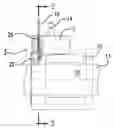
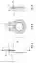
As is shown in the partially sectioned side view in FIG. 1, an electromagnetic actuating apparatus has a housing body 10, on which an insulating section 12 for forming a contact plug unit rests. The body 10 carries a guide tube 11 having a central inner diameter (ID) passageway for accommodating an armature assembly 13. In addition to a contact pair 14 for the coil apparatus (e.g., coil-on-spool) 15 in the housing 10, the contact plug unit has a ground contact plug (ground contact) 16 in the form of a strip-shaped/elongated stamped part, which at one end forms a free end (for electrical contact-making externally), and at the other end a fork-shaped engagement section 18 (FIG. 2) for interacting with a projection (tab) 20 of a disk-shaped yoke flange 22 of the arrangement shown in FIG. 1. The coil is energizable via the contacts to longitudinally/axially shift the armature. The shift may be against a single or bi-directional restoring spring bias.
In more precise terms, and in particular with reference to the sectional view in FIG. 2 and the detail of FIG. 3, it is shown that, in the exemplary embodiment shown, the fork-shaped engagement region 18 forms a pair of free tongues, which at least partially surround (or touch; in the context of the present invention the contact-making on both sides shown in FIG. 2 is also “surrounding” in this sense) the cylindrical (pin-shaped) projection 20. The fork tongues define (are separated by a recess/channel/slot which accommodates the projection. The recess has a beveled/convergent mouth to guide the projection during insertion of the ground contact and facilitate a lateral gripping of the projection by the tongues when installed.
This not only simplifies the manufacture of the element 16 significantly (simple stamping without any bending operation being required), but also the fitting takes place by means of insertion or simple snapping-in, barbs 24 formed in the lateral region of the stamped part 16 preventing unintentional sliding-out of the contact lug 16. The recess may have a widened area to detent the projection in the installed/inserted condition.
Sealing of the ground contact arrangement against the unintentional ingress of moisture, dust or the like takes place in the exemplary embodiment in FIGS. 1 to 3 by virtue of the introduction of liquid sealing means 26 into the slot.
The second exemplary embodiment in FIGS. 4 to 6 corresponds structurally and functionally virtually identically to the above-described exemplary embodiments; components which have not been provided with reference symbols or which have been provided with identical reference symbols correspond directly to the first exemplary embodiment. As can be seen in particular from the sectional view of FIG. 6 (detail from FIG. 4), in this exemplary embodiment a sealing body 30 is additionally inserted into the insulator 12 into a corresponding end-side cutout 32, however, in such a way that suitable rubber or silicone sealing material surrounds the contact 16 in sealing fashion.
Claims
What is claimed is:1. Electromagnetic actuating apparatus with an armature unit, which is guided axially in a housing (10, 22, 11) and is capable of being moved by means of energizing a coil apparatus held on a spool, contact plug means (14, 16), which are held in an insulator unit (12), being associated with the coil apparatus, and an elongated ground contact (16) of the contact plug means being electrically conductively connected to the housing,
characterized in that
the ground contact interacts electrically conductively at an engagement end which is opposite its free end with a yoke section (22), which is associated with the housing at the front end, in such a way that, in a fitted state, a cutout formed in the engagement end in the ground contact engages over a projection (20) of the yoke section and/or at least partially surrounds it.
2. Apparatus according to claim 1, characterized in that the engagement end of the ground contact is designed so as to open in the form of a fork in such a way that the ground contact can be pushed in a sprung and/or snap-action manner on or over the projection.
3. Apparatus according to claim 1, characterized in that the strip-shaped ground contact is a stamped part, and is guided in a slot formed in the insulator unit.
4. Apparatus according to claim 3, characterized in that the slot has sealing means, which acts between the insulator unit and the stamped part and prevents foreign substances from entering from the direction of the free end.
5. Apparatus according to claim 4, characterized in that the sealing means has a sealing element, which can be inserted into the insulator unit at the edge.
6. Apparatus according to claim 5, characterized in that the sealing element is a silicone and/or rubber seal surrounding the ground contact.
7. Apparatus according to claim 1, characterized in that the projection (20) is formed out of a ferromagnetic yoke element (22), at least sections of which are disk-shaped and/or ring-shaped.
8. Apparatus according to claim 7, characterized in that the projection is cylindrical and is designed to interact with a cutout, which is circular in sections, in the engagement end of the ground contact.
9. Apparatus according to claim 1, characterized in that the ground contact has barb means (24) on a narrow edge side which make it more difficult to withdraw the ground contact in the state in which it is inserted into the insulator unit.
10. Apparatus according to claim 1, characterized in that the apparatus is in the form of a water-tight and/or pressure-tight hydraulic or pneumatic magnet.
11. Electromagnetic actuating apparatus comprising:
a housing (10, 22, 11);
an armature unit (13), which is guided axially in the housing (10, 22, 11);
a coil apparatus (15) energizable to shift the armature unit; and
contact plug means (14, 16), which are held in an insulator unit (12), being associated with the coil apparatus a ground contact (16) of the contact plug means being electrically conductively connected to the housing,
wherein:
the ground contact interacts electrically conductively at an engagement end which is opposite its free end with a yoke section (22), which is associated with the housing at the front end, in such a way that, in a fitted state, a cutout formed in the engagement end in the ground contact engages over a projection (20) of the yoke section and/or at least partially surrounds it.
12. The apparatus of claim 11 wherein:
the projection is integrally formed with an annular flange of the yoke as a single piece.
13. The apparatus of claim 11 wherein:
the ground contact comprises an unbent stamping.
14. An electromagnetic actuating apparatus comprising:
a housing (10, 22, 11);
a coil apparatus (15) within the housing;
an insulator unit (12);
plug contacts (14, 16) which are held partially in the insulator unit, each contact having a free end protruding from the insulator, and including:
a pair of contacts (14) being associated with the coil apparatus; and
a ground contact (16) being electrically conductively connected to the housing; and
a yoke (22), which is associated with the housing at an end of the housing, the yoke having:
a projection (20), the ground contact electrically coupled at an engagement end which is opposite its free end with the projection in such a way that, in a fitted state, a recess formed in the engagement end of the ground contact engages the projection.
15. The apparatus of claim 14 further comprising:
an armature unit (13), which is guided axially in the housing (10, 22, 11), the coil apparatus energizable via the pair of contacts to axially shift the armature unit.
16. The apparatus of claim 14 wherein:
the engagement end of the ground contact is designed so as to open in the form of a fork defining the recess and shaped so that the ground contact can be installed via insertion via a sprung and/or snap-action manner of the fork on or over the projection.
17. The apparatus of claim 16 wherein:
the ground contact comprises a flat stamping having barbs (24) on a pair of narrow edge sides oriented to preferentially make it more difficult to withdraw the ground contact.
18. The apparatus of claim 16 wherein:
the ground contact is captured in a slot formed in the insulator unit;
the slot has sealing means for acts between the insulator unit and the ground contact and preventing foreign substances from entering from the direction of the ground contact free end.
19. The apparatus of claim 18 wherein:
the sealing means has a sealing element inserted into the insulator unit at an edge of the insulator.
20. The apparatus of claim 19 wherein:
the sealing element is a silicone and/or rubber seal surrounding the ground contact.
Images & Drawings included:
Sources:
- United States Patent and Trademark Office - verify current appl. status at the USPTO↗
Similar patent applications:
- » 20160099096
Electromagnetic actuating apparatus - » 20150213936
Bistable electromagnetic actuating apparatus, armature assembly and camshaft adjustment apparatus - » 20150322830
Electromagnetic actuating apparatus - » 20140253265
Electromagnetic actuating apparatus, in particular for camshaft adjustment of an internal combustion engine - » 20060044096
Electromagnetic actuator and composite electromagnetic actuator apparatus - » 20100000482
Electromagnetic actuating apparatus - » 9862374
Electromagnetic actuator and composite electromagnetic actuator apparatus - » 20090189724
Electromagnetic actuating apparatus - » 20110133576
Electromagnetic actuating apparatus - » 20160118174
Electromagnetic actuating apparatus
Recent applications in this class:
- » 20240321495 2024-09-26
GEOMAGNETIC FIELD AMPLIFIER DEVICE, SYSTEM, AND METHOD - » 20230045455 2023-02-09
Tibore the spring loaded unit - » 20220157503 2022-05-19
COIL MODULE AND ACTUATOR EQUIPPED WITH SAME - » 20200279683 2020-09-03
Manufacturing method of an integrated driving module with energy conversion function - » 20200075211 2020-03-05
Integrated driving module with energy conversion function and manufacturing method thereof - » 20190385773 2019-12-19
MAGNETIC FIELD GENERATORS BASED ON HIGH MAGNETIC PERMEABILITY MATERIALS - » 20190355502 2019-11-21
Electromagnetic coil connection assembly - » 20180342339 2018-11-29
Magnetic field generators based on high magnetic permeability materials - » 20180182523 2018-06-28
Polarity-switching magnet diode - » 20170372826 2017-12-28
Magnetization alignment in a thin-film device
Recent applications for this Assignee:
- » 20250094756 2025-03-20
MULTIFUNCTIONAL TAG - » 20240175515 2024-05-30
Bi-stable solenoid device, moving magnet actuator, valve and method for operating the bi-stable solenoid device - » 20230331319 2023-10-19
Sensor device and method for monitoring the coupling state of a coupling element - » 20230260393 2023-08-17
TRAFFIC MANAGEMENT DEVICE, TRAFFIC MANAGEMENT SYSTEM, TRAFFIC INFORMATION SYSTEM, STARTING MODULE THAT CAN BE RETROFITTED AND METHOD FOR MANAGING TRAFFIC - » 20230243441 2023-08-03
Electromagnetic Positioning Device with Position Detection - » 20230179430 2023-06-08
Copy protection method and copy-protected electronic system - » 20230112610 2023-04-13
Method for assigning a creator to a digital media file and/or for distributing the digital media file, recording device and display device - » 20220384079 2022-12-01
Electromagnetic actuator with intermediate position - » 20220364650 2022-11-17
ROTARY SLIDE VALVE FOR REGULATING A FLOW OF FLUID, AND METHOD FOR PRODUCING A ROTARY SLIDE VALVE - » 20220347620 2022-11-03
Particulate filtration device, fuel vapor recovery system, vehicle and method for a particulate filtration