Multi-row thrust ball bearing with unsymmetrical load distribution
US20080247699A1
2008-10-09
12/078,814
2008-04-07
✅ Patent granted
US 7,918,608 B2
2011-04-05
-
-
Marcus Charles
2029-06-11
Abstract:
An axial bearing arrangement has at least two rolling-contact bearings (1, 2), each of which includes one outer ring (3, 4) and at least one inner ring (5, 6). The inner rings (5, 6) are axially fixedly mounted on a shaft (7). The outer ring (8) of a first bearing (1) is axially slideably located on a casing (9) by at least one elastically deformable tensioning element (8). The outer ring (4) of a second bearing (2) is axially slideably located on the casing (9) and engageable against at least one stop (10) of the casing (9), when moved in the axial direction.
Assignee:
- Rolls-Royce Deutschland Ltd & Co KG 231 🇩🇪 , Germany
Interested in similar patents?
Get notified when new applications in this technology area are published.
Classification:
F16C33/60 IPC
Parts of bearings; Special methods for making bearings or parts thereof; Parts of ball or roller bearings; Raceways; Race rings divided or split, e.g. comprising two juxtaposed rings
F16C39/04 » CPC main
Relieving load on bearings using hydraulic or pneumatic means
F16C19/54 » CPC further
Bearings with rolling contact, for exclusively rotary movement Systems consisting of a plurality of bearings with rolling friction
F16C19/541 » CPC further
Bearings with rolling contact, for exclusively rotary movement; Systems consisting of a plurality of bearings with rolling friction Systems consisting of juxtaposed rolling bearings including at least one angular contact bearing
F16C33/581 » CPC further
Parts of bearings; Special methods for making bearings or parts thereof; Parts of ball or roller bearings; Raceways; Race rings integral with other parts, e.g. with housings or machine elements such as shafts or gear wheels
F16C39/02 » CPC further
Relieving load on bearings using mechanical means
F16C19/06 » CPC further
Bearings with rolling contact, for exclusively rotary movement with bearing balls essentially of the same size in one or more circular rows for radial load mainly with a single row or balls
F16C19/163 » CPC further
Bearings with rolling contact, for exclusively rotary movement with bearing balls essentially of the same size in one or more circular rows for both radial and axial load with a single row of balls with angular contact
F16C27/045 » CPC further
Elastic or yielding bearings or bearing supports, for exclusively rotary movement; Ball or roller bearings, e.g. with resilient rolling bodies with a fluid film, e.g. squeeze film damping
F16C2360/23 » CPC further
Engines or pumps Gas turbine engines
F16C23/06 IPC
Bearings for exclusively rotary movement adjustable for aligning or positioning Ball or roller bearings
F16C33/58 IPC
Parts of bearings; Special methods for making bearings or parts thereof; Parts of ball or roller bearings Raceways; Race rings
Description
This application claims priority to German Patent Application DE102007016591.0 filed Apr. 5, 2007, the entirety of which is incorporated by reference herein.
This invention relates to a multi-row thrust ball bearing with unsymmetrical load distribution.
For axially loaded bearings of aircraft engines, single-row ball bearings in three-point or four-point configuration are usually employed.
At high rotational speeds and high axial loads, the load-carrying capacity of these bearings is limited since either the contact stress occurring between rolling bodies and raceways exceeds the permissible maximum or service-life is below the required values. Currently existing multi-row bearing concepts are incapable of providing a definable load distribution over all bearing rows as well as under changing temperature conditions with pronounced temperature gradients from inside to outside.
The present invention, in a broad aspect, provides for an axial bearing arrangement of the type specified above, which is capable of transmitting high axial loads, features a long service-life and is characterized by simple design and easy, cost-effective producibility.
According to the present invention, an axial bearing arrangement with at least two rolling-contact bearings is provided, each of which includes one outer ring and at least one inner ring, with the inner rings being axially fixedly mounted on a shaft, with the outer ring of a first bearing being axially slideably located on a casing by at least one elastically deformable tensioning element, and with the outer ring of a second bearing being axially slideably located on the casing and settable against at least one stop of the casing, when moved in the axial direction.
The present invention accordingly provides for a defined distribution of the bearing load over both bearings (bearing rows). This allows the individual bearings/bearing rows to be exactly calculated as regards their functional characteristics, in particular, contact stress (stress in rolling contact) and speed of drift (slide, slip), for example.
Furthermore, the axial bearing arrangement according to the present invention is capable of accepting temperature gradients without any problems. This allows broad operating spectra to be covered, as required on aircraft engines.
Further design features, such as squeeze-oil dampers acting between the outer ring and the casing to provide hydraulic vibration damping, can be integrated without any problems.
The axial bearing arrangement according to the present invention is further advantageous in that it is compactly designed and can be embodied with low weight.
Furthermore, the bearing arrangement according to the present invention is also capable of accepting a load reversal.
The present invention is more fully described in the light of the accompanying drawings showing preferred embodiments. In the drawings,
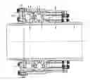
FIG. 1 is an axial partial sectional view of the axial bearing arrangement in accordance with the present invention,
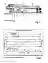
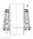
FIGS. 2 to 4 show different load conditions of the axial bearing arrangement shown in FIG. 1,
FIG. 5 is a total sectional view analogically to FIGS. 1 to 4, and
FIG. 6 is a diagram of the load distribution over both bearings.
The bearing arrangement according to present invention employs two or more ball bearings which take up the axial loads in a non-uniform, but defined manner. For simplicity, the following description is confined to two bearing rows, but it is also applicable to more rows.
A ball bearing of the bi-directional type (bearing capable of taking up axial loads in two directions) is connected to the structure by elastic rods. It takes up the loads occurring throughout the whole operating spectrum, though only up to a maximum load F1,max.
The second bearing may be provided as a unidirectional bearing (bearing capable of taking up axial loads in only one direction); it is freely moveable opposite to the direction of load and serves to take up peak loads. While the second bearing can experience significantly higher loads than the first bearing, the second bearing is, during most of the operating phases, only minimally loaded with a force F2.0 such that sliding problems are avoided. Only if the load to be transmitted Fax exceeds a value of F1,max+F2.0, the entire surplus load F2,Sp=Fax−F1,max is taken up by the second bearing.
The bearing arrangement according to the present invention is schematically shown in FIG. 1, with FIGS. 2 to 4 illustrating three typical load distribution cases.
The Figures show a first bearing 1 with an outer ring 3 and an inner ring 5 (which may also be of two-part design) and a second bearing 2 with an outer ring 4 and an inner ring 6, with both bearings being secured to a shaft 7 and pre-loaded against a shoulder 13 by a shaft nut 12 and spacers 18, 19.
Attached to a casing 9 is an elastically deformable tensioning element 8 (elastic beam or rod) which is connected to the outer ring 3 of the first bearing 1.
The outer ring 4 of the second bearing 2 is axially pre-loaded by an elastic element 11 (spring) via a pressure element 17, with an air gap 15 (so) positioned between a stop 10 (stop ring) and the outer ring 4. The entire bearing is adjustable via the stop 10 which is attached to the casing 9 with at least one intermediate spacer 16 (shim).
The slots 14 shown on the outer rings 3, 4 provide for hydraulic damping (squeeze-oil dampers), as known from the state of the art, and also enable the outer rings 3, 4 to be axially moved relative to the casing 9.
In operation, the two bearing outer rings 3, 4 move in the direction of load relative to the casing 9, so that the air gap 15 (s0) between the outer ring 4 of bearing 2 and the stop ring 10 is at maximum at low loads and decreases with increasing loads, amounting to 0 on reaching F1,max+F2.0. The minimum load F2.0 on bearing 2 is, in this example, provided by a helical spring (elastic element 11), but other types of pre-loading by pneumatic, hydraulic, mechanic or other mechanisms are also possible.
As from this point, no further increase of the loads transmitted via bearing 1 can occur, and all additional axial forces of the shaft 7 will be transmitted via bearing 2.
The air gap between the two bearing outer rings 3, 4 has no defined size. However, it must be provided such that load reversal will not result in contact between the two bearing rings 3, 4.
The shim (spacer 16) must be available in different thicknesses. It serves for compensating manufacturing tolerances and setting the air gap 15 (s0).
The spacers 18, 19 locate the bearing inner rings 5, 6 of bearing 1 and bearing 2 on the shaft 7. The bearing pack is axially secured via the retaining washer 20 and the shaft nut 12. Their relative position is independent of the axial shaft load.
As initial values, the permissible air gap s0 (defined by the max. permissible axial movement of the shaft) and the maximum load F1,max on bearing 1 are to be defined. This enables the required elastic rod length to be determined using the material characteristics yield point up and modulus of elasticity E as:
l B = a · s 0 · E σ P
and the sum of the elastic rod cross-sectional areas as:
A = a · F 1 , max σ P
(a=safety factor, relation of yield point σP and maximum tensile stress in the elastic rods σB,max: a=σP/σB,max).
Here, the maximum load on bearing 1 is settable such that the service-life of both bearing rows, as determined over a standard cycle of the shaft load, is equalized. The present invention also provides for designs optimized in terms of installation envelope.
The shaft load applied is distributed asymmetrically, but in a defined manner, on both bearings 1, 2. Until abutment of the end face of bearing 2 onto the stop ring 10, the load F2.0 is constantly transmitted via bearing 2. At zero load on the shaft, bearing 1 initially transmits the reverse pre-load F2.0. With the shaft load rising to FW=(F2.0+F1,max), initially only the load on bearing 1 is increased, with the load increase leading to an elongation of the elastic rods (elastically deformable tensioning element 8) according to Hooke's Law. Upon abutment of bearing 2 on the stop ring 10, no further elongation of the elastic rods 8, and thus no further increase of the loading on bearing 1, can occur. All additional loads will now be transmitted via bearing 2 only. The relation is shown in FIG. 5. In one embodiment, the outer ring 3 of the first bearing 1 is moveable between 20/100 mm and 10/100 mm by the elastically deformable tensioning element 8.
LIST OF REFERENCE NUMERALS
1 First bearing
2 Second bearing
3, 4 Outer ring
5, 6 Inner ring
7 Shaft
8 Elastically deformable tensioning element/elastic rod
9 Casing
10 Stop/stop ring
11 Elastic element (spring)
12 Shaft nut
13 Shoulder
14 Slot
15 Airgap s0
16 Spacer/shim
17 Pressure element
18 Spacer
19 Spacer
20 Retaining washer
Claims
What is claimed is:1. An axial bearing arrangement, comprising:
at least two rolling-contact bearings, each having one outer ring and at least one inner ring, wherein the inner rings are axially fixedly mounted on a shaft, the outer ring of a first bearing is axially slideably located on a casing by at least one elastically deformable tensioning element and that the outer ring of a second bearing is axially slideably located on the casing and engageable against at least one stop of the casing, when moved in the axial direction.
2. The axial bearing arrangement of claim 1, wherein the outer ring of the second bearing is elastically preloaded in a direction of the first bearing.
3. The axial bearing arrangement of claim 2, wherein a position of the stop of the casing is adjustable.
4. The axial bearing arrangement of claim 3, wherein the first bearing is adapted for taking up axial loads in two directions.
5. The axial bearing arrangement of claim 4, wherein the outer ring of the first bearing is moveable between 20/100 mm and 10/100 mm by the elastically deformable tensioning element.
6. The axial bearing arrangement of claim 5, wherein the two outer rings are always axially spaced apart.
7. The axial bearing arrangement of claim 6, and further comprising an elastic element for applying the pre-load against the outer ring of the second bearing.
8. The axial bearing arrangement of claim 7, wherein the first bearing is loadable up to a maximum load and the second bearing is loaded at an axial load greater than or equal to the sum of the pre-load and the maximum load of the first bearing.
9. The axial bearing arrangement of claim 1, wherein a position of the stop of the casing is adjustable.
10. The axial bearing arrangement of claim 1, wherein the first bearing is adapted for taking up axial loads in two directions.
11. The axial bearing arrangement of claim 1, wherein the outer ring of the first bearing is moveable between 20/100 mm and 10/100 mm by the elastically deformable tensioning element.
12. The axial bearing arrangement of claim 1, wherein the two outer rings are always axially spaced apart.
13. The axial bearing arrangement of claim 9, and further comprising an elastic element for applying a pre-load against the outer ring of the second bearing in a direction toward the first bearing.
14. The axial bearing arrangement of claim 13, wherein the first bearing is loadable up to a maximum load and the second bearing is loaded at an axial load greater than or equal to the sum of the pre-load and the maximum load of the first bearing.
15. The axial bearing arrangement of claim 1, and further comprising an elastic element for applying a pre-load to the second bearing.
16. The axial bearing arrangement of claim 15, wherein the first bearing is loadable up to a maximum load and the second bearing is loaded at an axial load greater than or equal to the sum of the pre-load and the maximum load of the first bearing.
Images & Drawings included:


Sources:
- United States Patent and Trademark Office - verify current appl. status at the USPTO↗
Recent applications in this class:
- » 20190368549 2019-12-05
Axial load management system - » 20110317948 2011-12-29
Hydrodynamic foil bearing assembly - » 20090074561 2009-03-19
Axial thrust offloading device
Recent applications for this Assignee:
- » 20160158679 2016-06-09
Aircraft engine with an apparatus for separating oil and a device for increasing pressure - » 20160069265 2016-03-10
Air guiding device and aircraft engine with air guiding device - » 20150367459 2015-12-24
Rolling tool device - » 20150260403 2015-09-17
Combustion chamber of a gas turbine - » 20150260402 2015-09-17
Combustion chamber of a gas turbine - » 20150260401 2015-09-17
Combustion chamber of a gas turbine - » 20150209915 2015-07-30
Method for repairing an abradable coating of a compressor of a gas turbine - » 20150176434 2015-06-25
Washer of a combustion chamber tile of a gas turbine - » 20150068262 2015-03-12
Apparatus and method for shot peening of blade mounting areas on a rotor arrangement disc - » 20150047191 2015-02-19
Method for balancing and assembling a turbine rotor