Antenna structure for a notebook
US20080252548A1
2008-10-16
11/735,461
2007-04-14
✅ Patent granted
US 7,525,492 B2
2009-04-28
-
-
Hoang V Nguyen
2027-07-13
Abstract:
An antenna structure for a notebook comprising a main body of an antenna and a printed circuit board which is provided on the main body of the antenna and is electrically connected; and the printed circuit board is laid out thereon at least with a radio frequency matched line, the radio frequency matched line can be adjusted to get a desired bandwidth.
Assignee:
- Auden Techno Corp 2 🇹🇼 Taoyuan Hsien, Taiwan
Interested in similar patents?
Get notified when new applications in this technology area are published.
Classification:
H01Q9/42 » CPC main
Electrically-short antennas having dimensions not more than twice the operating wavelength and consisting of conductive active radiating elements; Resonant antennas with feed to end of elongated active element, e.g. unipole with folded element, the folded parts being spaced apart a small fraction of the operating wavelength
H01Q1/50 IPC
Details of, or arrangements associated with, antennas Structural association of antennas with earthing switches, lead-in devices or lightning protectors
H01Q1/24 IPC
Details of, or arrangements associated with, antennas; Supports; Mounting means by structural association with other equipment or articles with receiving set
Description
BACKGROUND OF THE INVENTION
1. Field of the Invention
The present invention relates to an antenna structure, and especially to an antenna structure which suits a notebook.
2. Description of the Prior Art
In progression of mobile communication, notebooks get the basic function of mobile communication, and antennas become necessary elements for emitting signals in radio communication. On the requirement of compactness, the interior of a notebook has limited space for receiving an antenna, this makes designing of notebooks in present days encounter a problem of insufficiency of bandwidth desired. Even when a bandwidth is obtained by adjustment by the way of resonance, the original highly efficient structure of the antenna will be destroyed by the fact that a broadband obtained by resonance (resonant bandwidth) is a false resonance, thereby the efficiency of the antenna becomes worse; and this needs improvement.
SUMMARY OF THE INVENTION
The main object of designing of the present invention is to make an antenna structure able to complement the insufficiency of space structurally or the insufficiency of its desired bandwidth to get a better efficiency.
The antenna for a notebook provided by the present invention is composed of a main body of the antenna and a printed circuit board. The printed circuit board is provided on the main body of the antenna and is electrically connected; and is provided thereon with a radio frequency matched line, the radio frequency matched line can be adjusted to get a desired bandwidth and can reduce the influence on the efficiency of the main body of the antenna by space.
The present invention will be apparent in its structure and operational function after reading the detailed description of the preferred embodiment thereof in reference to the accompanying drawings.
BRIEF DESCRIPTION OF THE DRAWINGS
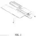
FIG. 1 is a perspective view showing the appearance of the present invention;
FIG. 2 is a perspective view of the present invention in a detached state;
FIG. 3 is a test chart showing the returnloss of the main body of the antenna of the present invention when the printed circuit board is added and not added respectively.
DETAILED DESCRIPTION OF THE PREFERRED EMBODIMENT
Referring to FIGS. 1 and 2, an antenna structure of a notebook provided by the present invention is composed of a main body 10 of an antenna and a printed circuit board 20.
The main body 10 of the antenna is made of metal. In the drawing shown, the main body 10 of the antenna is a planar antenna which is provided between a feed-in end and a grounding end with a plurality of cut recesses to form two radiating elements and form different loops in order to become a broad band antenna.
The printed circuit board 20 (PCB) is provided on the main body 10 of the antenna and is electrically connected; and is laid out thereon with a radio frequency (RF) matched line, the radio frequency matched line can be adjusted very easily to get a desired bandwidth that originally is unable obtained by adjustment, thus can reduce the influence on the efficiency of the main body 10 of the antenna by space.
The antenna structure of the present invention renders the main body 10 of the antenna better if the latter is good in function originally, and to be complemented to improve the function if the latter is not good in function originally.
Referring to FIG. 3 which is a test chart showing the returnloss of the main body 10 of the antenna of the present invention when the printed circuit board 20 is added and not added respectively, in the drawing, a range “T” is the desired bandwidth, wherein the main body 10 of the antenna without adding the printed circuit board 20 is insufficient for the high frequency portion, an in the range “T”, the main body 10 of the antenna with the added printed circuit board 20 can make its bandwidth increased after matching.
The followings are data for function comparison of a main body of the antenna having an added printed circuit board with a main body of the antenna without adding a printed circuit board respectively:
(1) The main body of the antenna without adding a printed circuit board:
| Frequency (MHz) | 880 | 915 | 960 | 1710 | 1880 | 1990 | 2170 |
| Anttenna Port Input | 0.00 | 0.00 | 0.00 | 0.00 | 0.00 | 0.00 | 0.00 |
| Power (dBm) | |||||||
| Total Radiation | −3.57 | −3.24 | −3.24 | −4.10 | −2.77 | −3.48 | −6.32 |
| Power (dBm) | |||||||
| Peak EIRP (dBm) | 0.44 | −0.25 | −0.25 | −0.44 | 1.00 | 0.97 | −1.60 |
| Directiviey (dBi) | 4.01 | 2.99 | 2.99 | 3.66 | 3.76 | 4.45 | 4.72 |
| Efficiency (dB) | −3.57 | −3.24 | −3.24 | −4.10 | −2.77 | −3.48 | −6.32 |
| Efficiency (%) | 44.00% | 47.44% | 47.44% | 38.91% | 52.86% | 44.83% | 23.33% |
| Gain (dBi) | 0.44 | −0.25 | −0.25 | −0.44 | 1.00 | 0.97 | −1.60 |
| Average Gain (dB) | −3.57 | −3.24 | −3.24 | −4.10 | −2.77 | −3.48 | −6.32 |
| Mobile efficiency (%) | 44.00% | 47.44% | 47.44% | 38.91% | 52.86% | 44.83% | 23.33% |
(2) The main body of the antenna with an added printed circuit board:
| Frequency (MHz) | 880 | 915 | 960 | 1710 | 1880 | 1990 | 2170 |
| Anttenna Port Input | 0.00 | 0.00 | 0.00 | 0.00 | 0.00 | 0.00 | 0.00 |
| Power (dBm) | |||||||
| Total Radiation | −3.50 | −3.20 | −3.47 | −3.13 | −2.95 | −2.96 | −3.24 |
| Power (dBm) | |||||||
| Peak EIRP (dBm) | −0.57 | 0.58 | 0.12 | 0.39 | 0.11 | 1.75 | 1.46 |
| Directiviey (dBi) | 3.23 | 3.78 | 3.79 | 3.93 | 3.06 | 4.71 | 5.10 |
| Efficiency (dB) | −3.50 | −3.20 | −3.47 | −3.13 | −2.95 | −2.96 | −3.24 |
| Efficiency (%) | 44.63% | 47.87% | 45.00% | 48.60% | 50.72% | 50.59% | 47.46% |
| Gain (dBi) | −0.57 | 0.58 | 0.12 | 0.39 | 0.11 | 1.75 | 1.46 |
| Average Gain (dB) | −3.50 | −3.20 | −3.47 | −3.13 | −2.95 | −2.96 | −3.24 |
| Mobile efficiency | 44.63% | 47.87% | 45.00% | 48.60% | 50.72% | 50.59% | 47.46% |
| (%) | |||||||
The above disclosed is a main body of an antenna made of metal added with a small printed circuit board, a radio frequency matched line is made taking advantage of the printed circuit board to complement the insufficiency of the bandwidth of the main body of the antenna and to increase the function of the antenna. Any value of frequency can be used with the antenna structure of the present invention.
Having now particularly described and ascertained the novelty and improvement of my invention and in what manner the same is to be performed, what we claim will be declared in the claims followed.
Claims
1. An antenna structure for a notebook comprising:
a main body of an antenna made of metal; and
a printed circuit board provided on said main body of said antenna and being electrically connected; and said printed circuit board is laid out thereon at least with a radio frequency matched line, said radio frequency matched line is adapted to being adjusted to get a desired bandwidth.
2. The antenna structure for a notebook as defined in claim 1, wherein, said main body of said antenna is a planar antenna.
Images & Drawings included:


Sources:
- United States Patent and Trademark Office - verify current appl. status at the USPTO↗
Similar patent applications:
- » 20070040754
Notebook and antenna structure thereof - » 20080278401
Antenna structure for a notebook - » 20120281162
Notebook computer and liquid crystal display module having particular antenna structure
Recent applications in this class:
- » 20250273866 2025-08-28
Antenna Arrangement Comprising a Plurality of Integrated Antennas - » 20250202121 2025-06-19
ELECTRONIC DEVICE AND ANTENNA FEEDING MODULE - » 20250174902 2025-05-29
ANTENNA STRUCTURE - » 20250149797 2025-05-08
ANTENNA MODULE - » 20240372264 2024-11-07
INVERTED L ANTENNA WITH MECHANICAL LC TANK CIRCUIT - » 20240322439 2024-09-26
Self-Decoupling Wideband Antenna System and Terminal Device - » 20240313410 2024-09-19
TERMINAL MONOPOLE ANTENNA - » 20240291156 2024-08-29
ANTENNA ASSEMBLY FOR A TOMOGRAPHY SYSTEM - » 20240258703 2024-08-01
METAL PLATE ANTENNA AND ANTENNA DEVICE - » 20240258702 2024-08-01
INVERTED L ANTENNA AND ANTENNA DEVICE
Recent applications for this Assignee:
- » 20140097997 2014-04-10
Metal frame antenna for a display