LIQUID DISPENSING DEVICE
US20080257908A1
2008-10-23
11/738,891
2007-04-23
Abstract:
A liquid dispensing device (1) having an elongated handle (2) with a distal end (3) and a proximal end (4), a bottle retaining housing (5) located on the handle (2) for the acceptance of a liquid-filled bottle (6), an electric motor (7), a trigger (15) in electrical connection with the motor (7), a pump (15) located within the bottle retaining housing (5) and in electrical connection with the electric motor (7) wherein the pump (8) is in fluid connection with the liquid (14), a spray nozzle (9) in fluid connection with the pump (8) via a conduit (10), an open and closeable valve (11), a spray pattern adjustment control (12) located proximate to the spray nozzle (9), a spray pattern adjustment control (12) and a removable wheel (13) located on the distal end (3) of the handle (2). The liquid dispensing device is operational when an electrical current is supplied to the motor (7) to create a predetermined amount of pressure to open the valve (11) and permit a predetermined amount of liquid (14) to flow from the bottle (6) and exit through the nozzle (9).
Interested in similar patents?
Get notified when new applications in this technology area are published.
Classification:
B05B9/0416 » CPC main
Spraying apparatus for discharge of liquids or other fluent material, without essentially mixing with gas or vapour characterised by means for supplying liquid or other fluent material with pressurised or compressible container ; with pump with pumps for liquids or other fluent material with pumps comprising rotating pumping parts, e.g. gear pump, centrifugal pump, screw-type pump
A01C23/047 » CPC further
Distributing devices specially adapted for liquid manure or other fertilising liquid, including ammonia, e.g. transport tanks or sprinkling wagons; Distributing under pressure; Distributing mud; Adaptation of watering systems for fertilising-liquids Spraying of liquid fertilisers
A01M21/043 » CPC further
Apparatus for the destruction of unwanted vegetation, e.g. weeds; Apparatus for destruction by steam, chemicals, burning, or electricity by chemicals
B05B1/1645 » CPC further
Nozzles, spray heads or other outlets, with or without auxiliary devices such as valves, heating means with multiple outlet openings ; with strainers in or outside the outlet opening having selectively- effective outlets with a selecting mechanism comprising a gate valve, a sliding valve or a cock by relative rotative movement of the valve elements the outlets being rotated during selection
B05B1/169 » CPC further
Nozzles, spray heads or other outlets, with or without auxiliary devices such as valves, heating means with multiple outlet openings ; with strainers in or outside the outlet opening having selectively- effective outlets having three or more selectively effective outlets
B05B9/007 » CPC further
Spraying apparatus for discharge of liquids or other fluent material, without essentially mixing with gas or vapour At least a part of the apparatus, e.g. a container, being provided with means, e.g. wheels, for allowing its displacement relative to the ground
B05B9/0861 » CPC further
Spraying apparatus for discharge of liquids or other fluent material, without essentially mixing with gas or vapour characterised by means for supplying liquid or other fluent material with pressurised or compressible container ; with pump; Apparatus to be carried on or by a person, e.g. of knapsack type with a liquid pump the pump being motor-driven the motor being electric
Description
BACKGROUND OF THE INVENTION
This invention relates to liquid dispensing devices, more particularly, a liquid dispensing device that permits a user to quickly and easily dispense a liquid onto a surface.
Currently, many individuals use hand-held pump reservoir systems to spray liquid fertilizer and/or pesticides on a lawn. The user adds a predetermined amount of liquid to the reservoir, secures a cap thereon, pressurizes the reservoir and sprays the liquid onto the lawn. However, many individuals find the use of such reservoirs difficult as the user must carry the reservoir over the entire area to be sprayed and must repeatedly pump the reservoir to provide a predetermined amount of pressure to spray the liquid. Moreover, because the reservoir is filled with liquid, the user tires easily due to the weight he/she must carry while spraying the lawn. In addition, the entire system is cumbersome to carry due to the bulk of the reservoir.
Moreover, many individuals utilize the same hand-held pump reservoir systems to spray a liquid ice-melter solution onto iced-over sidewalks, driveways and other grounds during the winter to remove ice. For the aforementioned reasons, however, many individuals find using such a system difficult.
Thus, a need exists for a liquid dispensing device that permits a user to quickly and easily dispense liquid onto a surface.
The relevant prior art includes the following references:
| U.S. Pat. No. | ||
| (U.S. unless stated otherwise) | Inventor | Issue/Publication Date |
| 4,408,720 | Anderson et al. | Oct. 11, 1983 |
| 6,805,304 | Nokes et al. | Oct. 19, 2004 |
| 6,279,838 | Sivells et al. | Aug. 28, 2001 |
| 6,135,361 | Grassi | Oct. 24, 2000 |
| 5,946,851 | Adey et al. | Sep. 07, 1999 |
| 2004/0084552 | Huartson | May 06, 2004 |
| 5,695,121 | Stillions, Jr. et al. | Dec. 09, 1997 |
| 4,524,912 | Jones | Jun. 25, 1985 |
| 4,865,255 | Luvisotto | Sep. 12, 1989 |
| 5,752,661 | Lewis | May 19, 1998 |
| 6,663,306 | Policicchio et al. | Dec. 16, 2003 |
SUMMARY OF THE INVENTION
The primary object of the present invention is to provide a liquid dispensing device that permits a user to quickly dispense liquid onto a surface.
Another object of the present invention is to provide a liquid dispensing device that is easy to use.
A further object of the present invention is to provide a liquid dispensing device that is easily portable.
An even further object of the present invention is to provide a liquid dispensing device that is self-contained electrically-powered.
Another object of the present invention is to provide a liquid dispensing device that may be used in conjunction with a variety of liquids.
An even further object of the present invention is to provide a liquid dispensing device that allows for integrated pest management wherein a small amount of liquid is discharged, thereby preventing waste and/or pollution.
The present invention fulfills the above and other objects by providing a liquid dispensing device having an elongated handle, which may be adjustable telescopically, having a proximal end and a distal end, a bottle retaining housing located on the handle for the acceptance of a liquid-filled bottle, an electric motor located within the bottle retaining housing, the bottle retaining housing having a receiving means for acceptance of a bottle opening, a trigger in electrical connection with the motor and located on the proximal end of the handle, a pump located within the bottle retaining housing and in electrical connection with the electric motor wherein the pump is in fluid connection with the predetermined amount of liquid in the bottle, a spray nozzle located on the distal end of the handle and in fluid connection with the pump via a conduit, an open and closeable valve located in the conduit between the spray nozzle and the pump, a spray pattern adjustment control located proximate to the spray nozzle, a spray pattern adjustment means located within the spray nozzle and a removable wheel located on the distal end of the handle. The liquid dispensing device is operational when an electrical current is supplied to the motor to create a predetermined amount of pressure to open the valve and permit a predetermined amount of liquid to flow from the bottle and exit through the nozzle. A voltage source, such as batteries located in a battery housing on the proximal end of the handle so as to have the liquid dispensing device completely self-contained and portable, provides power to the electric motor.
To use the liquid dispensing device of the present invention, a person opens a bottle filled with a predetermined liquid, such as liquid fertilizer, pesticide, herbicide, ice-melt, etc., and inserts the bottle into the bottle retaining house wherein the bottle opening is facing the distal end of the handle. Then, the user pushes a safety button located on the proximal end of the handle and pulls the trigger to spray the liquid onto a surface. The user may then roll the liquid dispensing device of the present invention along the surface to spray the desired surface area. Finally, the user may adjust the spray pattern of the spray nozzle by manipulating the spray pattern adjustment control. The adjustment of the spray pattern is ideal for difficult to reach surface areas, such as stairs, corners or areas located beneath or behind vegetation.
If the user desires to elongate or shorten the handle, then he or she presses a length adjustment button located on the handle. In this manner, the user is better able to reach various surfaces of varying distances from the location of the user.
The above and other objects, features and advantages of the present invention should become even more readily apparent to those skilled in the art upon a reading of the following detailed description in conjunction with the drawings wherein there is shown and described illustrative embodiments of the invention.
BRIEF DESCRIPTION OF THE DRAWINGS
In the following detailed description, reference will be made to the attached drawings in which:
FIG. 1 is a side view of a liquid dispensing device of the present invention;
FIG. 2 is a front view of a liquid delivery means of the liquid dispensing device of the present invention;
FIG. 3 is side plan view of a nozzle of the liquid dispensing device of the present invention;
FIG. 4 is a front plan view of a nozzle of the liquid dispensing device of the present invention; and
FIG. 5 is a side view of an alternate embodiment of a liquid dispensing device of the present invention.
DESCRIPTION OF THE PREFERRED EMBODIMENTS
For purposes of describing the preferred embodiment, the terminology used in reference to the numbered components in the drawings is as follows:
- 1. liquid dispensing device, generally
- 2. handle
- 3. handle distal end
- 4. handle proximal end
- 5. bottle retaining housing
- 6. bottle
- 7. electric motor
- 8. pump
- 9. spray nozzle
- 10. conduit
- 11. valve
- 12. spray pattern adjustment control
- 13. wheel
- 14. liquid
- 15. trigger
- 16. battery compartment housing
- 17. electrical connection
- 18. aperture
- 19. adjustment disk
- 20. adjustment means
- 21. V-shaped pattern
- 22. linear-shaped pattern
- 23. circular-shaped pattern
- 24. liquid delivery means
- 25. gears
- 26. safety button
- 27. length adjustment button
- 28. inner handle
- 29. outer handle
- 30. AC adapter
- 31. electrical receptacle
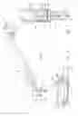
With respect to FIG. 1, a side view of a liquid dispensing device of the present invention is shown. The liquid dispensing device, generally 1, includes an elongated handle 2 having a distal end 3 and a proximal end 4 and a bottle retaining housing 5 secured on the handle 2. The bottle retaining house 5 is sized and shaped so as to receive a bottle 6 containing a liquid 14 therein, which may be pesticide, herbicide, fertilizer, ice-melt or any other liquid in which a user may desire to spray onto a ground surface. A conduit 10 fluidly connects the liquid 14 in the bottle 6 to a pump 8 and fluidly connects the pump 8 to a nozzle 9 located on the handle distal end 3 wherein the liquid 14 is discharged. A spray pattern adjustment control 12 permits a user to select the type of spray pattern which will be emitted from the nozzle 9. A wheel 13, which is preferably removable, is secured to the handle distal end 3 so as to permit a user to quickly and easily move the liquid dispensing device 1 over a surface. To use the present device, a user squeezes the trigger 15 so as to discharge the liquid 14 from the bottle 6 through the nozzle 9 and onto a surface. The liquid dispensing device 1 is electrically-powered via a voltage source, which is preferably rechargeable batteries located within a battery compartment housing 16 located on the handle proximal end 4, so as to be a completely self-contained and portable device. A safety button 26 is preferably located on the handle proximal end 4 so as to prevent liquid 14 from exiting the nozzle 9. In addition, the inclusion of the safety button 26 aids in preventing children from using the liquid dispensing device 1 without adult supervision.
In FIGS. 2 and 3, varying views of a liquid delivery means of the liquid dispensing device of the present invention is shown. The liquid delivery means 24 preferably includes an electric motor 7 located within the bottle retaining housing 5 that is in electrical connection 17 with a voltage source, such as batteries located within the battery compartment housing 16. The electric motor 7 is also in electrical connection 17 with a pump 8 having gears 25. The pump 8 is fluidly-connected to the bottle 6 containing liquid 14 and to the nozzle 9 via conduits 10. A valve 11 is located within the conduit 10 connecting the pump 8 to the nozzle 9 so as to prevent discharging of liquid 14 when the electric motor 7 is not powered. An adjustment means 20 connects the spray pattern adjustment control 12 to an adjustment disk 19 located within the nozzle 9 so as to rotate the adjustment disk 19 when the spray pattern adjustment control 12 is turned.
When the trigger 15 is squeezed, power is provided from a voltage source to the electric motor 7, which in turn activates the pump 8. When the pump 8 is activated, the gears 25 of the pump 8 rotate to generate a pressure sufficient to open the valve 11 so that the liquid 14 can flow through the nozzle 9 and exit via the aperture 18.
Next, FIG. 4 is a front plan view of a nozzle of the liquid dispensing device of the present invention. The nozzle 9 includes an aperture 18 to permit discharge of the liquid 14. Located within the nozzle 9 is the adjustment disk 19, which preferably includes a plurality of differently-shaped patterns, such as a V-shaped pattern 21 to create a fan-shaped discharge of the liquid 14, a linear-shaped pattern 22 and a circular-shaped pattern 23. When the spray pattern adjustment control 12 is turned, the adjustment means 20 that connects the spray pattern adjustment control 12 to the adjustment disk 19 rotates, so as to rotate the adjustment disk 19 to expose the desired pattern to the aperture 18. When the desired pattern is in line with the aperture 18, the liquid 14 dispersed from the bottle 6 through the nozzle 9 must first pass through the selected pattern, thereby allowing for the discharge of liquid 14 in the desired pattern. The use of predetermined patterns, which include the shapes described above and any others, is especially useful when spraying a surface that is not level, such as in the case of stairs, or includes obstacles, such as trees, flowers or other items located on the surface but not needing to be sprayed.
Finally, FIG. 5 shows a side view of an alternate embodiment of the liquid dispensing device 1 of the present invention. The alternate embodiment includes all of the features noted above. However, the handle 2 of the alternate embodiment is adjustable telescopically so as to permit a user to access various surface areas of varying distances from the user. The handle 2 includes an inner handle 28 and an outer handle 29 wherein the inner handle 28 is retractable within the outer handle 29. A length adjustment button 27, which is preferably located on the handle 2 but may be located elsewhere on the liquid dispensing device 1, permits a user to adjust the length of the handle 2 by pressing the length adjustment button 27 and pushing or pulling the inner handle 28 into or out of the outer handle 29. In addition, the alternate embodiment may include an AC adapter 30 which may be plugged into an electrical receptacle 31 so as to provide a power supply to the liquid dispensing device 1.
The use of the present invention will permit a person to quickly and easily dispense a liquid onto a surface.
It is to be understood that while a preferred embodiment of the invention is illustrated, it is not to be limited to the specific form or arrangement of parts herein described and shown. It will be apparent to those skilled in the art that various changes may be made without departing from the scope of the invention and the invention is not be considered limited to what is shown and described in the specification and drawings.
Claims
Having thus described my invention, I claim:1. A liquid dispensing device comprising:
an elongated handle having a proximal end and a distal end;
a bottle retaining housing located on the handle;
an electric motor located within the bottle retaining housing;
a bottle having a predetermined amount of liquid therein;
the bottle retaining housing having a receiving means for acceptance of a bottle opening;
a trigger located on the proximal end of the handle;
said trigger in electrical connection with the electric motor;
a pump located within the bottle retaining housing and in electrical connection with the electric motor;
said pump in fluid connection with the predetermined amount of liquid in the bottle;
a spray nozzle located on the distal end of the handle and in fluid connection with the pump via a conduit;
an open and closeable valve located in the conduit between the spray nozzle and the pump;
a spray pattern adjustment control located proximate to the spray nozzle;
an adjustment means located within the spray nozzle and operable via the spray pattern adjustment control;
said pump is operational when an electrical current is supplied to the motor to create a predetermined amount of pressure to open the valve and permit a predetermined amount of liquid to flow from the bottle and exit through the nozzle;
a removable wheel located on the distal end of the handle; and
a voltage source for providing power to the electric motor.
2. The liquid dispensing device of claim 1 wherein:
said liquid is a pesticide.
3. The liquid dispensing device of claim 1 wherein:
said liquid is a herbicide.
4. The liquid dispensing device of claim 1 wherein:
said liquid is an ice-melter.
5. The liquid dispensing device of claim 1 wherein:
said liquid is a fertilizer.
6. The liquid dispensing device 1 wherein:
said voltage source is at least one battery.
7. The liquid dispensing device of claim 1 wherein:
said voltage source is an AC adapter which may be plugged into an electrical receptacle.
8. The liquid dispensing device of claim 1 wherein:
said spray pattern adjustment control creates a circular spray pattern.
9. The liquid dispensing device of claim 1 wherein:
said spray pattern adjustment control creates a linear spray pattern.
10. The liquid dispensing device of claim 1 wherein:
said spray pattern adjustment control creates a V-shaped spray pattern.
11. The liquid dispensing device of claim 1 further comprising:
a safety button located on the proximal end of the handle wherein the safety button prevents liquid from exiting the nozzle.
12. The liquid dispensing device of claim 6 wherein:
said at least one battery is located within a battery housing on the proximal end of the handle.
13. The liquid dispensing device of claim 7 wherein:
said AC adapter is located within a battery housing on the proximal end of the handle.
14. The liquid dispensing device of claim 12 wherein:
the at least one battery is rechargeable.
15. A liquid dispensing device comprising:
an elongated handle having a proximal end and a distal end;
a bottle retaining housing located on the handle;
an electric motor located within the bottle retaining housing;
a bottle having a predetermined amount of liquid pesticide therein;
the bottle retaining housing having a receiving means for acceptance of a bottle opening;
a trigger located on the proximal end of the handle;
said trigger in electrical connection with the electric motor;
a pump located within the bottle retaining housing and in electrical connection with the electric motor;
said pump in fluid connection with the predetermined amount of liquid in the bottle;
a spray nozzle located on the distal end of the handle and in fluid connection with the pump via a conduit;
an open and closeable valve located in the conduit between the spray nozzle and the pump;
a spray pattern adjustment control located proximate to the spray nozzle;
an adjustment means located within the spray nozzle and operable via the spray pattern adjustment control;
said pump is operational when an electrical current is supplied to the motor to create a predetermined amount of pressure to open the valve and permit a predetermined amount of liquid to flow from the bottle and exit through the nozzle;
a removable wheel located on the distal end of the handle; and
a voltage source located on the handle second end for providing power to the electric motor wherein the voltage source is at least one battery.
16. The liquid dispensing device of claim 15 wherein:
said at least one battery is rechargeable.
17. A liquid dispensing device comprising:
an elongated handle having a proximal end and a distal end;
a bottle retaining housing located on the handle;
an electric motor located within the bottle retaining housing;
a bottle having a predetermined amount of liquid therein;
the bottle retaining housing having a receiving means for acceptance of a bottle opening;
a trigger located on the proximal end of the handle;
said trigger in electrical connection with the electric motor;
a pump located within the bottle retaining housing and in electrical connection with the electric motor;
said pump in fluid connection with the predetermined amount of liquid in the bottle;
a spray nozzle located on the distal end of the handle and in fluid connection with the pump via a conduit;
an open and closeable valve located in the conduit between the spray nozzle and the pump;
a spray pattern adjustment control located proximate to the spray nozzle;
an adjustment means located within the spray nozzle and operable via the spray pattern adjustment control;
said spray pattern adjustment control creates a linear spray pattern, a V-shaped spray pattern and a circular pattern;
said spray pattern adjustment control creates a circular spray pattern;
said pump is operational when an electrical current is supplied to the motor to create a predetermined amount of pressure to open the valve and permit a predetermined amount of liquid to flow from the bottle and exit through the nozzle;
a removable wheel located on the distal end of the handle; and
a voltage source located on the handle second end for providing power to the electric motor wherein the voltage source is at least one battery.
18. The liquid dispensing device of claim 15 wherein:
said elongated handle is telescopic wherein an inner handle is extendable from an outer handle.
19. The liquid dispensing device of claim 17 wherein:
said elongated handle is telescopic wherein an inner handle is extendable from an outer handle.
Images & Drawings included:


Sources:
- United States Patent and Trademark Office - verify current appl. status at the USPTO↗
Similar patent applications:
- » 20230415179
LIQUID DISPENSING DEVICE FOR A HIGH PRESSURE CLEANING DEVICE AND METHOD FOR CONTROLLING A HIGH PRESSURE CLEANING DEVICE BY MEANS OF A LIQUID DISPENSING DEVICE - » 20060102737
Volatile liquid dispensing device and method for releasing volatile compounds using a volatile liquid dispensing device - » 20130108521
Discharge device and liquid dispensing device, and method for dispensing liquid - » 20220175196
Display device, liquid dispenser, and use of a display device on a liquid dispenser - » 20250099985
LIQUID DISPENSING DEVICE AND LIQUID DISCHARGE SYSTEM - » 20110077557
Medical ultrasound device with liquid dispensing device coupled to a therapy head - » 20050273918
Liquid dispensing device with secondary liquid entrance - » 20060032867
Liquid dispensing device - » 20060032868
Liquid dispensing device - » 20060112990
Liquid dispensing device and method
Recent applications in this class:
- » 20240024902 2024-01-25
Double tentacle pump system for a liquid sprayer - » 20210291209 2021-09-23
Double tentacle pump system for a liquid sprayer - » 20200061647 2020-02-27
Spray structure for portable atomizer - » 20190210048 2019-07-11
Spray structure for portable atomizer - » 20190047002 2019-02-14
Variable volume strand coating apparatus and method - » 20140346248 2014-11-27
REMOVAL DEVICE FOR A CROP PROTECTION AGENT - » 20130277455 2013-10-24
Portable airless sprayer - » 20080128534 2008-06-05
SPRAY PUMP SYSTEM AND COUPLING APPARATUS - » 20060283972 2006-12-21
Fountain that flows with fluidic material