Sprinkler head location indicator
US20080296406A1
2008-12-04
12/068,663
2008-02-08
Abstract:
The sprinkler head location indicator is a shallow dish adapted for placement on the shaft of a pop-up sprinkler head. The dish is concave upward and has a small pilot hole formed through its center. A plurality of radially extending guidelines is formed on the bottom surface of the dish, the guidelines having hash marks at uniform intervals to form scale markings. The guidelines are severed radially to a uniform length forming flexible segments and the dish is pushed up the shaft to the ground flange of the sprinkler head. The flexible segments bend against the sprinkler head shaft, thereby retaining the dish on the shaft.
Interested in similar patents?
Get notified when new applications in this technology area are published.
Classification:
A01G13/0281 » CPC main
Protecting plants; Protective coverings for plants; Devices for laying-out coverings; Ground coverings Protective ground coverings for individual plants, e.g. for plants in pots
B05B15/16 » CPC further
Details of spraying plant or spraying apparatus not otherwise provided for; Accessories; Arrangements for preventing or controlling structural damage to spraying apparatus or its outlets, e.g. for breaking at desired places; Arrangements for handling or replacing damaged parts for preventing non-intended contact between spray heads or nozzles and foreign bodies, e.g. nozzle guards
B05B15/622 » CPC further
Details of spraying plant or spraying apparatus not otherwise provided for; Accessories; Arrangements for mounting, supporting or holding spraying apparatus; Arrangements for supporting spraying apparatus, e.g. suction cups ground-penetrating
B05B15/74 » CPC further
Details of spraying plant or spraying apparatus not otherwise provided for; Accessories; Arrangements for moving spray heads automatically to or from the working position using hydraulic or pneumatic means driven by the discharged fluid
Y10T137/7043 » CPC further
Fluid handling; With casing, support, protector or static constructional installations Guards and shields
B05B15/00 IPC
Details of spraying plant or spraying apparatus not otherwise provided for; Accessories
Description
CROSS-REFERENCE TO RELATED APPLICATION
This application claims the benefit of U.S. Provisional Patent Application Ser. No. 60/924,730, filed May 29, 2007.
BACKGROUND OF THE INVENTION
1. Field of the Invention
The present invention generally relates to lawn sprinklers, and particularly to a sprinkler head location indicator for locating pop-up sprinkler heads.
2. Description of the Related Art
Accidental damage to pop-up sprinkler heads and the PVC pipe to which they are attached often occurs because the heads are hidden in tall grass and are hit or run over by a lawn mower. The sprinkler heads are often knocked off completely or knocked out of their set positions, causing the sprinklers to water the street, sidewalk, the walls of a building or cars in a driveway. In addition, grass frequently grows up around the sprinkler heads, preventing the proper operation of the pop-up mechanism. In some instances, the pop-up sprinkler head is not installed flush with the ground, but remains raised slightly above the ground when the sprinkler is retracted. Such installations are commonly used with gardens, flower beds, hedges, and the like to ensure that the sprinkler will elevate high enough to spray water over the vegetation, foliage, bushes, etc. Such pipes and sprinkler heads are thin and sometimes difficult to distinguish, resulting in damage to the sprinkler head during landscaping activities. Thus, a sprinkler head location indicator solving the aforementioned problems is desired.
SUMMARY OF THE INVENTION
The sprinkler head location indicator is a shallow dish adapted for placement on the shaft of a pop-up sprinkler head. The dish is concave upward and has a small pilot hole formed through its center. A plurality of radially-extending guidelines are formed on the bottom surface of the dish, the guidelines having hash marks at uniform intervals to form scale markings at various diameters. In use, the guidelines are severed radially to a uniform length slightly smaller than the diameter of the shaft of the sprinkler head, and the dish is pushed up the shaft to the ground flange of the sprinkler head. The dish is formed of a flexible, resilient material, so that the segments formed by severing the guidelines flex and bend against the sprinkler head shaft, thereby retaining the dish on the shaft.
The dish provides a visible indicator marking the location of the sprinkler head that is readily apparent to avoid damage to the sprinkler head when operating lawn mowers or other landscaping equipment. Since the dish is resiliently held against the sprinkler head shaft, grass cannot grow between the indicator and the sprinkler head, preventing the sprinkler head from being covered by vegetation. Moreover, since the indicator is resiliently held against the sprinkler head shaft, the sprinkler head location indicator may be used with sprinkler heads that are not flush with the ground when retracted, but extend above the ground.
These and other features of the present invention will become readily apparent upon further review of the following specification and drawings.
BRIEF DESCRIPTION OF THE DRAWINGS
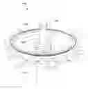
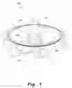
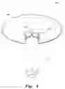
FIG. 1 is an environmental, perspective view of a sprinkler head location indicator according to the present invention.
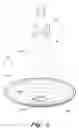
FIG. 2 is a perspective view of the sprinkler head location indicator according to the present invention.
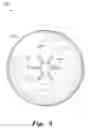
FIG. 3 is a bottom view of the sprinkler head location indicator according to the present invention.
FIG. 4 is an environmental perspective view the sprinkler head location indicator according to the present invention attached to a sprinkler head housing as seen from below.
Similar reference characters denote corresponding features consistently throughout the attached drawings.
DETAILED DESCRIPTION OF THE PREFERRED EMBODIMENT
The present invention is a sprinkler head location indicator, designated generally as 100 in the drawings, for marking the location of pop-up sprinkler heads. As shown in FIGS. 1 and 2, the sprinkler head location indicator 100 is a shallow dish 102 having a concave upper face 104 and a convex lower face 106, which directs grass surrounding the sprinkler head to grow outward, away from the sprinkler head. The dish 102 has pilot hole 108 formed through its center. The pilot hole 108 has a small diameter, preferably smaller than the diameter of conventional sprinkler head shafts. The diameter of the pilot hole 108 may be, e.g., about one-half inch. As shown in FIG. 3, a plurality of radially extending guidelines 110 are formed on the lower face 106 (the bottom surface) of the dish 102. The guidelines 110 may comprise a slight ridge, a shallow depression, a thinned area, perforations, a painted line, or any other form of visual or tactile indicia to mark radially extending lines on the lower face 106. The guidelines 110 have a plurality of hash marks 112 forming scale markings at uniform length intervals along the radial guidelines 110.
In use, the user may use scissors, a utility knife, or any other suitable cutting instrument to sever each of the radially extending guidelines 110 so that the severed portions of the guidelines 110 extend to a length slightly smaller than the diameter of the shaft 114 of the sprinkler head 116. The hash marks 112 are provided to assist the user in severing the guidelines 110 to a uniform length. Severing the guidelines 110 forms a plurality of retainer tabs or flaps 118. The dish 102 is formed of a flexible, resilient material, such as polyvinyl resin or other suitable material, and is also durable, lightweight, shatterproof, rugged, waterproof, and may be treated with additives to prevent discoloration by ultraviolet radiation from exposure to sunlight.
After the guidelines 110 have been uniformly severed, the dish 102 is pushed onto the shaft of the 114 of the sprinkler head 116 up to the ground-mounting flange or collar 120, as shown in FIG. 4, and the shaft 114 may then be threaded onto the underground water supply pipe (not shown). The flexible, resilient nature of the retainer tabs 118 causes the dish 102 to snuggly engage the sprinkler head shaft 114, the tabs 118 bending and resiliently engaging the shaft 114. The close engagement of the dish 102 with shaft 114 prevents the growth of grass or weeds between the location indicator 100 and the sprinkler head 116, thus preventing the sprinkler head 116 from becoming entangled or hidden in undergrowth. Moreover, resilient engagement of the dish 102 with the shaft 114 permits the use of the location indicator 100 with sprinkler heads that are raised above ground for watering gardens, flower beds, bushes and shrubs, etc.
The provision of radially extending guidelines 110 with hash marks 112 to graduate the guidelines 110 permits the location indicator 100 to be adjusted to fit sprinkler heads having shafts of different diameter. The dish 102 may be formed in any desired color and in any diameter to render the location indicator 100 highly visible, and may be coated with fluorescent material for the same purpose, if desired. The sprinkler head location indicator 100 can be made decorative or more appealing to the eye by ornamentation that is printed, stamped, or coated onto the dish 102 simulating a flower, sport team logos, etc.
If run over by the wheels of a mower, the resilient nature of the location indicator 100 allows it to rebound back to its original shape. The location indicator 100 will not get sucked into a mower or become a projectile, even if hit by mower blades.
It is to be understood that the present invention is not limited to the embodiment described above, but encompasses any and all embodiments within the scope of the following claims.
Claims
I claim:1. A sprinkler head location indicator, comprising a shallow dish, the dish having:
an upper face and a lower face;
a pilot hole extending through a center of the dish;
a plurality of radially-extending guidelines defined on the lower face thereof, and
a plurality of hash marks defined at intervals on the guidelines to form scale markings for severing the guidelines to uniform length.
2. The sprinkler head location indicator according to claim 1, wherein said upper face is concave.
3. The sprinkler head location indicator according to claim 1, wherein said lower face is convex.
4. The sprinkler head location indicator according to claim 1 wherein said guidelines extend radially from said pilot hole.
5. The sprinkler head location indicator according to claim 1, wherein said shallow dish is fabricated from a flexible and resilient material.
6. A sprinkler head location indicator, comprising a shallow dish having:
an upper concave face and a lower convex face;
a pilot hole extending through a center of the dish;
a plurality of radially-extending guidelines defined on the lower convex face thereof, and
a plurality of hash marks defined at intervals on the guidelines to form scale markings for severing the guidelines to uniform length.
7. The sprinkler head location indicator according to claim 6 wherein said guidelines extend radially from said pilot hole.
8. The sprinkler head location indicator according to claim 6, wherein said shallow dish is fabricated from a flexible and resilient material.
9. A sprinkler head location indicator, comprising a shallow dish fabricated from flexible and resilient material, said dish having:
an upper concave face and a lower convex face;
a pilot hole extending through a center of the dish;
a plurality of radially-extending guidelines defined on the lower convex face thereof, said guidelines, when severed, defining retaining tabs for retaining said dish on a shaft of a pop-up sprinkler head; and
a plurality of hash marks defined at intervals on the guidelines to form scale markings for severing the guidelines to uniform length.
10. The sprinkler head location indicator according to claim 9 wherein said guidelines extend radially from said pilot hole.
Images & Drawings included:
Sources:
- United States Patent and Trademark Office - verify current appl. status at the USPTO↗
Similar patent applications:
- » 20100154898
Sprinkler head location indicator
Recent applications in this class:
- » 20240237593 2024-07-18
DEVICE FOR INHIBITING WEED GROWTH IN A POT - » 20240155982 2024-05-16
LOCKABLE INDOOR/OUTDOOR CULTIVATOR - » 20230157223 2023-05-25
Weed barrier and method of use - » 20220248615 2022-08-11
Weed Barrier/Moisture Retention Cover for Bagged or Potted Plants - » 20210243965 2021-08-12
MOWER PATH ASSISTANCE SYSTEM - » 20210185941 2021-06-24
Weed barrier and method of use - » 20210161084 2021-06-03
Tree or plant protection mat - » 20210100175 2021-04-08
Plant Pot Weed Skirt and Plant Wrap - » 20200178480 2020-06-11
Plant edging - » 20190387694 2019-12-26
MODULAR PLANT PROTECTION