Housing for electronic device and method of making the same
US20080297989A1
2008-12-04
11/933,965
2007-11-01
✅ Patent granted
US 7,755,880 B2
2010-07-13
-
-
Hung V Duong
2028-07-01
Abstract:
A housing (100) for an electronic device includes an opaque base (10). The base has a plurality of blind holes (120) and a number of through holes (140) defined therein. Each through hole communicates with a corresponding blind hole. The through holes are arrayed in a determined pattern.
Inventors:
- Jie Tang 23 🇨🇳 Shenzhen, China
- JIN-LIN QIU 2 🇨🇳 Shenzhen, China
- CHUN-BAO WANG 2 🇨🇳 Shenzhen, China
Assignee:
- FIH (HONG KONG) LIMITED 1,465 🇭🇰 Kowloon, Hong Kong
- SHENZHEN FUTAIHONG PRECISION INDUSTRY CO., LTD. 1,108 🇨🇳 ShenZhen City, China
- SUTECH TRADING LIMITED 185 Tortola, Virgin Islands (British)
- ShenZhen FuTaiHong Precision Industry Co., Ltd. 446 🇨🇳 Shenzhen, Guangdong Province, China
Interested in similar patents?
Get notified when new applications in this technology area are published.
Classification:
G06F1/16 IPC
Details not covered by groups - and Constructional details or arrangements
H05K5/0243 » CPC main
Casings, cabinets or drawers for electric apparatus; Details; Mechanical details of casings for decorative purposes
H05K5/0243 » CPC main
Casings, cabinets or drawers for electric apparatus; Details; Mechanical details of casings for decorative purposes
H04M1/0283 » CPC further
Substation equipment, e.g. for use by subscribers; Constructional features of telephone sets; Portable telephone sets, e.g. cordless phones, mobile phones or bar type handsets; Improving the user comfort or ergonomics for providing a decorative aspect, e.g. customization of casings, exchangeable faceplate
Y10T29/49117 » CPC further
Metal working; Method of mechanical manufacture; Electrical device making Conductor or circuit manufacturing
H05K5/00 IPC
Casings, cabinets or drawers for electric apparatus
H05K5/00 IPC
Casings, cabinets or drawers for electric apparatus
Description
BACKGROUND OF THE INVENTION
1. Field of the Invention
The present invention relates generally to housings, and particularly to a housing for an electronic device and a method of making the same.
2. Description of Related Art
With the development of wireless communication and information processing technologies, portable electronic devices, such as mobile telephones and personal digital assistants (PDAs), are now in widespread use. Since the electronic device ares carried as an everyday item, the appearance and tactile feel of the electronic device can be an important part of its appeal. Generally, producers apply spray painting or baked-on varnish to the housing of the electronic device so as to improve the appearance of the electronic device. However, the paint may easily be worn off, thus affecting the appearance of the electronic device.
Therefore, a new housing for electronic device is desired in order to overcome the above-described problems.
SUMMARY OF THE INVENTION
In one embodiment thereof, a housing is applied to an electronic device and includes an opaque base. The base has a plurality of blind holes and a number of through holes defined therein. Each through hole communicates with a corresponding blind hole. The through holes are arrayed in a pattern.
Other advantages and novel features will become more apparent from the following detailed description when taken in conjunction with the accompanying drawings.
BRIEF DESCRIPTION OF THE DRAWINGS
Many aspects of the housing for electronic device can be better understood with reference to the following drawings. The components in the drawings are not necessarily drawn to scale, the emphasis instead being placed upon clearly illustrating the principles of the present housing. Moreover, in the drawings, like reference numerals designate corresponding parts throughout the several views.
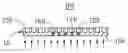
FIG. 1 is an isometric view of a housing, in accordance with a first embodiment of the present invention;
FIG. 2 is a cross-sectional view taken along line II-II of FIG. 1; and
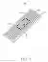
FIG. 3 is a cross-sectional view of a housing, in accordance with a second embodiment of the present invention.
DETAILED DESCRIPTION OF THE INVENTION
Referring now to FIGS. 1 and 2, a housing 100 applied to an electronic device (not shown) includes a base 10, in accordance with a first embodiment of the present invention. The base 10 is opaque and generally a flat board. The base 10 is made of metal in this embodiment, and has an upper surface 102 and a lower surface 104. A plurality of circular blind holes 120 are defined in the upper surface 102. A diameter of each blind hole 120 is about 0.3 mm, and the depth of each blind hole 120 is about 0.1˜0.2 mm. A number of circular through holes 140 are defined in the lower surface 104 and arrayed in pattern (e.g., landscape, portrait, and so on). Each through hole 140 communicates with a corresponding blind hole 120. A diameter of each through hole is much smaller than the blind hole 120. Some transparent filler 160 is inserted into each through hole 140 so as to avoid water or dust coming inside. Since each through hole 140 is small, the through holes 140 are hard for a user to see from outside. During use the electronic device gives out light from inside. The light escapes from the through holes 140 of the housing 100, so as to show the pattern brightly.
A method of manufacturing the housing 100 includes steps as follow:
- (1) providing a pressing machine to punch a metal so as to form the base 10;
- (2) using a laser engraving machine to carve the base 10 so as to form a plurality of blind holes 120 and a number of through holes 140, each blind hole 120 communicating with a given blind hole 120;
- (3) polishing the surface of the base 10 using a polish tool; and
- (4) clearing the base 10 and filling some transparent filler 160 into the through holes 140 for forming the housing 100.
In step (1), a height of the base 10 is about 0.5 mm, and the base 10 is a flat board.
In step (2), a diameter of each blind hole 120 is about 0.3 mm and the depth of each blind hole 120 is about 0.1˜0.2 mm. A diameter of each through hole 140 is about 0.2 mm, and the through holes 140 are arrayed in a determined pattern.
In step (3), the polishing tool has a polishing cloth used to polish the housing 10, wherein some lubricant is attached to the polishing cloth during polishing. Due to the polishing, irregularities formed on the surface of the base 10 gradually disappear. Thus, the surface of the base 10 becomes more smoother.
In a second embodiment of the present invention, referring to FIG. 3, the housing 200 includes a base 20. The base 20 has a plate 212 and two sidewalls 214 respectively extending from two sides of the plate 212. A plurality of blind holes 220 are defined in the plate 212 and the two sidewalls 214. A number of through holes 240 are formed in the plate 212 and the two sidewalls 214, and each through hole 240 communicates with a corresponding blind hole 220. The through holes 240 are arrayed in a pattern. Each through hole 240 and each blind hole 220 are filled with transparent filler 260, so that dust and other contaminants cannot enter into the blind hole 220.
It should be understood that the blind holes 120, 220 may be other shape, such as rectangular, rhomboid and so on.
It also should be understood that the diameter of the blind holes 120, 220 or the through hole 140, 240 may be changed according to requirement.
It is to be further understood that even though numerous characteristics and advantages of the present embodiments have been set forth in the foregoing description, together with details of the structures and functions of the embodiments, the disclosure is illustrative only, and changes may be made in detail, especially in matters of shape, size, and arrangement of parts within the principles of the invention to the full extent indicated by the broad general meaning of the terms in which the appended claims are expressed.
Claims
What is claimed is:1. A housing for an electronic device, comprising:
an opaque base having a plurality of blind holes defined therein, a number of through holes being defined in the base, each through hole communicating with a corresponding blind hole, the through holes being arrayed in a predetermined pattern.
2. The housing as claimed in claim 1, wherein each through hole is filled with transparent filler.
3. The housing as claimed in claim 2, wherein each blind hole is filled with transparent filler.
4. The housing as claimed in claim 1, wherein the base is made of metal.
5. The housing as claimed in claim 1, wherein each blind hole is circular.
6. The housing as claimed in claim 5, wherein each through hole is circular.
7. The housing as claimed in claim 1, wherein a diameter of the through hole is smaller than the diameter of the blind hole.
8. The housing as claimed in claim 7, wherein a diameter of each blind hole is 0.3mm, and a diameter of each through hole is 0.2 mm.
9. The housing as claimed in claim 8, wherein a depth of each blind hole is 0.1 mm˜0.2 mm.
10. A method of making a housing applied in an electronic device, comprising steps:
forming a base;
defining in the base a plurality of blind holes; and
defining in the base a plurality of through holes, each through hole communicating with a corresponding blind hole, the through holes being arrayed in pattern.
11. The method as claimed in claim 10, further comprising a step of filling transparent filler in each blind hole.
12. The method as claimed in claim 10, wherein the base is a metal and is formed by a pressing machine.
13. The method as claimed in claim 10, wherein the blind holes and the through holes are formed by a laser engraving machine.
14. The method as claimed in claim 10, further comprising a step of polishing the surface of the base after the through holes being defined.
15. The method as claimed in claim 14, further comprising a step of cleaning the base after polishing.
16. The method as claimed in claim 15, further comprising a step of filling transparent filler in each through hole after cleaning.
17. The method as claimed in claim 16, further comprising a step of filling transparent filler in each blind hole.
Images & Drawings included:


Sources:
- United States Patent and Trademark Office - verify current appl. status at the USPTO↗
Similar patent applications:
- » 20130257237
Housing for electronic devices and method for making housing - » 20200094518
THIN, HIGH-STIFFNESS LAMINATES, PORTABLE ELECTRONIC DEVICE HOUSINGS INCLUDING THE SAME, AND METHODS FOR MAKING SUCH LAMINATES AND PORTABLE ELECTRONIC DEVICE HOUSINGS - » 20090305001
HOUSING FOR ELECTRONIC DEVICE AND METHOD FOR MAKING THE HOUSING - » 20100108344
Housing for electronic device and method of making the housing - » 20140368388
HOUSING OF ELECTRONIC DEVICE, AND METHOD FOR MAKING THE HOUSING - » 20090009935
HOUSING FOR AN ELECTRONIC DEVICE AND METHOD FOR MAKING THE HOUSING - » 20120189842
ELECTRONIC DEVICE HOUSING AND METHOD FOR MAKING THE SAME - » 20130240350
ELECTRONIC DEVICE HOUSING AND METHOD FOR MAKING THE SAME - » 20110159258
Electronic device housing and method for making the same - » 20060092601
Method of making an electronic device housing
Recent applications in this class:
- » 20250267808 2025-08-21
DECORATIVE PLATE, COVER PLATE AND ELECTRONIC DEVICE - » 20250194033 2025-06-12
ELECTRICAL ENCLOSURE INCLUDING IN-MOLD DECORATION - » 20250185196 2025-06-05
ELECTRONIC DEVICE COMPRISING HOUSING WITH PATTERN, AND METHOD FOR FORMING PATTERN - » 20250176124 2025-05-29
DECORATIVE SUBSTRATE AND PREPARATION METHOD THEREFOR, COVER PLATE AND ELECTRONIC DEVICE - » 20250176123 2025-05-29
Decorative Plate and Preparation Method Therefor, and Electronic Device - » 20250113451 2025-04-03
DEEP-COLORED HOUSING AND ELECTRONIC DEVICE COMPRISING SAME - » 20250056744 2025-02-13
Housing Assembly, Housing Assembly Preparation Method, and Electronic Device - » 20250024617 2025-01-16
Decorative Plate and Manufacturing Method Therefor, and Electronic Device - » 20240298415 2024-09-05
Electrical Control Console for Watercraft - » 20240215185 2024-06-27
FOLDABLE ELECTRONIC DEVICES
Recent applications for this Assignee:
- » 20220140846 2022-05-05
Antenna structure and wireless communication device using same - » 20220094077 2022-03-24
Antenna structure and wireless communication device using same - » 20220059931 2022-02-24
Antenna structure and wireless communication device - » 20220021116 2022-01-20
Single antenna structure capable of operating in multiple band widths - » 20220010948 2022-01-13
Anti-loosing structure and backlight module - » 20200170133 2020-05-28
Housing, electronic device, and method for manufacturing same - » 20200122194 2020-04-23
Frame and surface treatment method for the frame - » 20200060034 2020-02-20
Housing, method for manufacturing the same, and electronic device having the same - » 20200016805 2020-01-16
Housing, electronic device, and method for manufacturing the same - » 20190368052 2019-12-05
COMPOSITE AND METHOD FOR MAKING SAME