Deflection pulley for a traction means
US20080300077A1
2008-12-04
12/095,863
2006-11-28
✅ Patent granted
US 8,651,988 B2
2014-02-18
WO; PCT/EP2006/068968; 20061128
WO; WO2007/063055; 20070607
William A Rivera | Henry Liu
Volpe and Koenig, P.C.
2030-02-14
Abstract:
A tensioning device for a traction element, such as a belt, band or chain, is provided having a tensioning arm (1) arranged on a machine part on which an idler pulley or deflection pulley for the traction element is rotatably mounted via a roller bearing (2), and includes a protective cap (15) which is in a frictionally locking or positively locking manner on the idler pulley and covers the bearing region of the idler pulley. The idler pulley is a sheet-metal sheave (16) and includes, for securing the protective cap (15), a snap-in groove (17) which is formed in an end region of the sheet-metal sheave (16) which has an outwardly conical shape, with the end region having a thickness (A) which is less than a thickness (E) of the sheet metal of the sheet-metal sheave (16).
Inventors:
- Benoit Kapfer 1 🇫🇷 Brumath, France
- Jacky Herrmann 1 🇫🇷 Dannelbourg, France
- Constant Einsetler 1 🇫🇷 Griesbach, France
Assignee:
- Schaeffler Technologies AG &Co. KG 4,023 🇩🇪 Herzogenaurach, Germany
- SCHAEFFLER KG 595 🇩🇪 Herzogenaurach, Germany
Applicant:
Interested in similar patents?
Get notified when new applications in this technology area are published.
Classification:
F16C13/006 » CPC further
Rolls, drums, discs, or the like ; Bearings or mountings therefor Guiding rollers, wheels or the like, formed by or on the outer element of a single bearing or bearing unit, e.g. two adjacent bearings, whose ratio of length to diameter is generally less than one
F16C33/723 » CPC further
Parts of bearings; Special methods for making bearings or parts thereof; Sealings Shaft end sealing means, e.g. cup-shaped caps or covers
F16C19/06 » CPC further
Bearings with rolling contact, for exclusively rotary movement with bearing balls essentially of the same size in one or more circular rows for radial load mainly with a single row or balls
F16C33/783 » CPC further
Parts of bearings; Special methods for making bearings or parts thereof; Sealings of ball or roller bearings with a diaphragm, disc, or ring, with or without resilient members; Details of the sealing or parts thereof, e.g. geometry, material of the mounting region
F16C2226/74 » CPC further
Joining parts; Fastening; Assembling or mounting parts; Positive connections with complementary interlocking parts with snap-fit, e.g. by clips
F16C2361/63 » CPC further
Apparatus or articles in engineering in general Gears with belts and pulleys
F16H2007/0865 » CPC further
Gearings for conveying rotary motion by endless flexible members; Means for varying tension of belts, ropes, or chains; Finally actuated members, e.g. constructional details thereof Pulleys
F16H7/12 IPC
Gearings for conveying rotary motion by endless flexible members; Means for varying tension of belts, ropes, or chains by adjusting the axis of a pulley of an idle pulley
F16H7/00 IPC
Gearing for conveying rotary motion by endless flexible members
F16H7/00 IPC
Gearings for conveying rotary motion by endless flexible members
F16H7/20 » CPC main
Gearings for conveying rotary motion by endless flexible members; Means for guiding or supporting belts, ropes, or chains Mountings for rollers or pulleys
F16H55/36 IPC
Elements with teeth or friction surfaces for conveying motion; Worms, pulleys or sheaves for gearing mechanisms; Friction members Pulleys
Description
BACKGROUND
The invention relates to a deflection pulley or a tensioning device for a traction element, such as a belt, band, or chain, with a tensioning arm, which is arranged on a machine part so that it can pivot and on which a deflection pulley for the traction element is mounted so that it can rotate via a roller bearing, and with a protective cap, which covers the bearing region of the deflection pulley and which is secured on the deflection pulley with a non-positive and/or positive fit connection.
With the protective cap of a deflection pulley or a tensioning device, the bearing region of the deflection pulley should be protected against the penetration of contaminants and sprayed water.
It is already known not to connect the protective cap of the deflection pulley to the deflection pulley with a non-positive or positive fit connection, but instead to construct it as a protective plate, which forms an annular gap with the deflection pulley. In this way, between the rotating deflection pulley and the protective plate fixed relative to the deflection pulley, a labyrinth seal is created, which, however, still does not allow the desired high sealing effect.
It is also known to form a rim for the detachable mounting of the protective cap on the deflection pulley with a steel sheave. Here, however, e.g., raising the edge of the rim through roll deformation requires an additional processing step in the manufacturing process of the deflection pulley, which results in extra costs.
The publication DE 100 24 318 A1 shows a tensioning device of the type noted above. As emerges there from FIG. 1 of the drawing, a protective cap is set axially on a hub of the deflection pulley and secured there with a friction fit connection. For such an arrangement with a steel sheave, it is also known to form a snap-in groove on the hub of the deflection pulley through turning. The protective cap can engage in this snap-in groove with a bead, so that a positive-fit connection is created. This, however, involves an expensive solution due to the necessary additional turning process.
SUMMARY
The invention is based on the objective of creating a deflection pulley or an idler device with a deflection pulley-protective cap unit, which guarantees a high degree of protection against the penetration of contaminants and sprayed water, wherein the deflection pulley should be manufactured in a simple process without additional processing steps.
This objective is met according to the invention in such a way that the deflection pulley is constructed as a sheet-metal sheave and has, for securing the protective cap, a snap-in groove, which is formed by an end region of the sheet-metal sheave deformed conically outward, wherein the end region has a smaller thickness dimension relative to the sheet-metal thickness of the sheet-metal sheave.
In this way, the deflection pulley constructed as a sheet-metal sheave can be manufactured completely by a single drawing process, e.g., on a transfer press. Here, the proposed snap-in groove for securing the protective cap is also produced during the drawing process of the sheet-metal sheave. In this configuration, additional manufacturing processes, such as raising the edge of the end region through roll deformation or the turning finishing work for forming a snap-in groove is avoided. For producing the snap-in groove, the material of the sheet-metal sheave only in the end region receiving the protective cap needs to be drawn thinner than in the other regions, after which the end region can be formed conically outward, in order to form the snap-in groove.
Due to the snap-in geometry according to the invention, the protective cap can be placed axially on the deflection pulley and drawn from there, without negatively affecting the snap-in function. The protective cap thus seals the bearing region of the deflection pulley from penetration of contaminants and streams of water.
BRIEF DESCRIPTION OF THE DRAWINGS
An embodiment of the invention is shown in the drawing and is described in more detail in the following in comparison with deflection pulley configurations according to prior state of the art.
Shown in partial sections are:
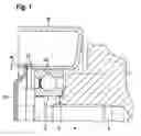
FIG. 1—an axial section view of a deflection pulley or idler roller-protective cap unit according to the invention, which is arranged on a tensioning arm, and
FIGS. 2 to 4—views of three known deflection pulley-protective cap units in diagrams corresponding to FIG. 1.
DETAILED DESCRIPTION OF THE PREFERRED EMBODIMENTS
The units shown in the figures of the drawing are each secured on a tensioning arm 1, which is mounted so that it can pivot on a not-shown machine part. The machine part can be mounted, for example, on an internal combustion engine. On each tensioning arm 1, a deflection pulley for a traction element is mounted so that it can rotate via a roller bearing 2. The rotational axis of the roller bearing 2 here extends parallel to the pivot axis of the tensioning arm 1. The bearing inner ring is supported axially on a contact face 3 of the tensioning arm 1 and is secured there by a screw 4, which is screwed into a threaded borehole 5 of the tensioning arm 1. The sheave 13 is mounted on the bearing outer ring of the roller bearing 2. The bearing region of the roller bearing 2 is covered and sealed outward with a protective cap 15, which attaches to an axial end of the deflection pulley.
The unit shown in FIG. 2 has a deflection pulley, which is configured as a sheet-metal sheave 6. Its inner part acting as a hub is enclosed by a protective cap configured as a protective plate 7, wherein an annular gap 8 is maintained between the sheet-metal sheave 6 and the protective plate 7. In this way, a labyrinth seal of the region of the roller bearing 2 is formed. This, however, does not allow the desired high sealing effect.
The unit according to FIG. 3 likewise has a deflection pulley, which is configured as a sheet-metal sheave 9. The sheet-metal sheave 9 is provided with a formed rim 10, which is encompassed by a bead 11 of a protective cap 12. This sheet-metal sheave 9 has the disadvantage that for the production of the rim 10, an additional processing step is required.
FIG. 4 shows a solid sheave 13 with a hub, in whose two axial end regions, snap-in grooves 14 are machined on the outer periphery. A protective cap 15 is placed on the hub of the deflection pulley 13 and is secured there with shaped beads, which engage in the adjacent snap-in groove 14. This configuration requires the formation of snap-in grooves 14, for example, through turning, as an additional work stage in the manufacturing of the sheave 13.
The deflection pulley-protective cap unit shown in FIG. 1 has a protective cap 15, as shown in FIG. 4, and a deflection pulley formed as a sheet-metal sheave 16. According to the invention, a snap-in groove 17 is configured in an axial end region of the hub part of the sheet-metal sheave 16 in such a way that the sheet-metal thickness “A” is here smaller than the sheet-metal thickness “E” in the remaining profile of the sheet-metal sheave 16 and that this end region is deformed conically outward. Such a sheet-metal sheave 16 has the advantage that it can be formed with the snap-in groove 17 in a single work stage of the work process.
REFERENCE SYMBOLS
- 1 Tensioning arm
- 2 Roller bearing
- 3 Contact face
- 4 Screw
- 5 Threaded borehole
- 6 Sheet-metal sheave
- 7 Protective plate
- 8 Gap
- 9 Sheet-metal sheave
- 10 Rim
- 11 Bead
- 12 Protective cap
- 13 Sheave
- 14 Snap-in groove
- 15 Protective cap
- 16 Sheet-metal sheave
- 17 Snap-in groove
- A Thickness measure
- E Sheet-metal thickness
Claims
1. A tensioning device for a traction element, comprising a tensioning arm, which is arranged on a machine part so that it can pivot and on which an idler or deflection pulley for the traction element is mounted so that it can rotate via a roller bearing, and a protective cap covers a bearing region of the idler or deflection pulley and is secured on the idler or deflection pulley with a friction or positive fit connection, the idler or deflection roller is a formed sheet-metal sheave, and for connection of the protective cap, includes a snap-in groove, which is formed by a conically outwardly shaped end region of the sheet-metal sheave that has a reduced thickness in comparison to a thickness of the sheet-metal sheave.
Images & Drawings included:


Sources:
- United States Patent and Trademark Office - verify current appl. status at the USPTO↗
Recent applications in this class:
- » 20250067323 2025-02-27
TOOTHED BELT AXIS FOR PROVIDING LINEAR MOVEMENT OF A CARRIAGE - » 20240110614 2024-04-04
Orbital tensile drive - » 20230028229 2023-01-26
Keyless coupling arrangement for a generator and associated methods - » 20220412439 2022-12-29
Fixed belt tensioner - » 20220282774 2022-09-08
ADJUSTABLE ANGULAR ORIENTATION OF A FREELY RUNNING SHEAVE OF A BELT DRIVE - » 20220056989 2022-02-24
Keyless coupling arrangement for a generator and associated methods - » 20210364067 2021-11-25
Pulley Mount - » 20200332869 2020-10-22
SLIDER RAIL FOR A V-BELT PULLEY DRIVE - » 20200263766 2020-08-20
Pulley device, in particular for tensioning idler or runner roller - » 20170363183 2017-12-21
ATTACHMENT METHOD FOR PULLEY DEVICE AND DRIVE SHAFT AND ASSEMBLY FORMED THEREBY
Recent applications for this Assignee:
- » 20250293624 2025-09-18
METHOD FOR DETERMINING AN INITIAL ROTOR POSITION OF A ROTOR, COMPUTER PROGRAM PRODUCT, CONTROL UNIT, ELECTRIC MACHINE, INSPECTION AND/OR TEST METHOD AND TEST STAND - » 20250290560 2025-09-18
TORQUE CONVERTER WITH PULLING BIAS SPRING - » 20250283516 2025-09-11
FREEWHEEL DEVICE AND FREEWHEEL CLUTCH - » 20250279708 2025-09-04
HYBRID DRIVE RESOLVER ROTOR MOUNTING ARRANGEMENT - » 20250273375 2025-08-28
DETENT SOLENOID - » 20250269726 2025-08-28
Electrical Circuit, On-Board Power Supply System, Vehicle, Method, Computer Program, And Computer-Readable Medium - » 20250269694 2025-08-28
ADJUSTMENT MECHANISM COMPRISING A LINEAR ACTUATOR, VEHICLE AND METHOD FOR OPERATING A VEHICLE - » 20250264157 2025-08-21
PLANETARY GEARBOX HAVING A ROTATIONALLY FIXED THRUST WASHER OF THE PLANET BEARING - » 20250263129 2025-08-21
WHEEL WELL GUARD FOR A WHEEL WELL OF A VEHICLE AND VEHICLE HAVING THE WHEEL WELL GUARD - » 20250262941 2025-08-21
Individual Monitoring Of A Plurality Of Output Points Of A System For The Vehicle-Based Supply Of External Loads