Modularized power supply switch control structure
US20090033151A1
2009-02-05
11/882,538
2007-08-02
✅ Patent granted
US 7,939,964 B2
2011-05-10
-
-
Jared J Fureman | Adi Amrany
2027-10-13
Abstract:
A modularized power supply switch control structure aims to control a main power system of a power supply. The main power system includes at least one high voltage output unit at a high voltage output end and one low voltage output unit at a rear low voltage output end. A control unit is connected to the high voltage output unit and the low voltage output unit to control start/stop time series of the high voltage output unit and the low voltage output unit so that the high voltage output unit and the low voltage output unit can be started asynchronously. Thus the power supply can output a start voltage at the start instant to meet load requirement. A plurality of power output modules deliver output asynchronously. Hence output current or voltage surge at the start instant can be improved.
Assignee:
- Zippy Technology Corp. 49 🇹🇼 Hsin-Tien, Taipei Hsien, Taiwan
Interested in similar patents?
Get notified when new applications in this technology area are published.
Classification:
H02M1/36 » CPC main
Details of apparatus for conversion Means for starting or stopping converters
H02M1/008 » CPC further
Details of apparatus for conversion; Converter structures employing plural converter units, other than for parallel operation of the units on a single load Plural converter units for generating at two or more independent and non-parallel outputs, e.g. systems with plural point of load switching regulators
H02M1/009 » CPC further
Details of apparatus for conversion; Converters characterised by their input or output configuration having two or more independently controlled outputs
H02J1/10 IPC
Circuit arrangements for dc mains or dc distribution networks Parallel operation of dc sources
H02J1/00 IPC
Circuit arrangements for dc mains or dc distribution networks
Description
FIELD OF THE INVENTION
The present invention relates to a modularized power supply switch control structure and particularly to a method and a circuit structure to control asynchronous start/stop sequence of a plurality of power supply modules in a power supply.
BACKGROUND OF THE INVENTION
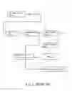
A conventional power supply, referring to FIG. 1, includes an EMI filter unit 2, a commutation unit 3, a power factor correction circuit 4, a standby power system 5, a pulse width modulation (PWM) unit 6 and a main power system 7. A first switch unit 11 is provided to control ON/OFF between the power supply and an AC power input source 9. The standby power system 5 is connected to a second switch unit 12 to control operation of the PWM unit 6. The main power system 7 has at least one high voltage output end (shown by 12V in FIG. 1) and at least one low voltage output end (shown by 5V and +3.3V in FIG. 1). However, the standby power system and the main power system do not adopt a modular power output structure. To provide different output watts design of element parameters of the standby power system or main power system has to be done anew. And there is no expandability. To improve the design of power supply and compatibility of the power supply of the same series, R.O.C. Patent No. 1260848 entitled “Chain control circuit for parallel power supply” includes a plurality of parallel power supplies connecting to a control unit through a power supply switch unit. The power supply switch unit issues signals so that the control unit orders the parallel power supplies to deliver output at the same time. The parallel power supplies also can output rated watts as deigned. Such a design can accumulate output watts of the power supplies to meet requirements. The number of the parallel power supplies can be increased or decreased to alter the output watts. Hence design of the power supply is more flexible and can be done faster. Repairs and maintenance also are simpler. However, ON/OFF of the power supplies are done at the same time under the order of the control unit. When the parallel power supplies are started simultaneously, an inrush current is generated that might cause damage of computer elements or trigger a protection mechanism to make the computer elements not able to start normally. There is still a need to control output of a plurality of power supplies coupled in parallel.
SUMMARY OF THE INVENTION
In view of the shortcomings occurred to the conventional power supply and prior art set forth above, the primary object of the present invention is to provide a method and a circuit structure to control start/stop time series of a plurality of power supply modules in a power supply to improve the phenomenon of inrush current at the instant of power ON period.
The invention provides a modularized power supply switch control structure to control a main power system of a power supply. The main power system includes at least a high voltage output unit at a high voltage output end and a low voltage unit at a rear low voltage output end. The high voltage output unit includes at least one first power output module. The low voltage unit includes at least one second power output module connecting to at least one DC/DC converter. It also has a control unit connecting to the high voltage output unit and the low voltage output unit to control start/stop time series of the high voltage output unit and the low voltage output unit so that they are started asynchronously. The instantaneous output voltage of the power supply can meet the requirement of the start voltage of a load to allow the load to be started normally. As the power supply modules do not deliver output at the same time, output current or voltage surge at the instant of start period can be improved.
The foregoing, as well as additional objects, features and advantages of the invention will be more readily apparent from the following detailed description, which proceeds with reference to the accompanying drawings.
BRIEF DESCRIPTION OF THE DRAWINGS
FIG. 1 is a block diagram of a conventional power supply structure.
FIG. 2 is a block diagram of the invention.
FIG. 3 is a circuit block diagram of the invention.
FIG. 4 is a detailed circuit block diagram of the invention.
DETAILED DESCRIPTION OF THE PREFERRED EMBODIMENT
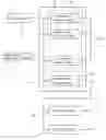
Please refer to FIGS. 2 and 3 for an embodiment of the invention. The invention is adopted for use on a power supply which is connected to an AC power input source 9. ON/OFF of the AC power is controlled through a first switch unit 11 to provide input power of the power supply through an EMI filter unit 2 and a commutation unit 3 to start a standby power system 5. The standby power system 5 provides power through a second switch unit 12 to start a PWM unit 6. The PWM unit 6 generates a duty cycle signal for a power factor correction circuit 4 and a main power system 7. The power goes through phase regulation through the power factor correction circuit 4 and is sent to the main power system 7. The PWM unit 6 and the main power system 7 are bridged by a control unit 8 which controls start time series of the main power system 7. Referring to FIG. 3, the main power system 7 includes at least a high voltage output unit 71 at a high voltage output end (shown by 12V in FIG. 3) and a low voltage unit 72 at a rear low voltage output end (shown by 5V and +3.3V in FIG. 3). In this embodiment the low voltage output unit 72 is connected to two DC/DC converters 73 to form respectively a low voltage output end of 5V and another low voltage output end of 3.3V. The start time series of the high voltage output unit 71 and the low voltage output unit 72 are controlled by the controlled unit 8. The control unit 8 receives the duty cycle signal of the PWM unit 6 to order the high voltage output unit 71 and the low voltage output unit 72 to start asynchronously. The control unit 8 also sets the start time series of the high voltage output unit 71 and the low voltage output unit 72 so that after the power supply is started, the high voltage output unit 71 or the low voltage output unit 72 can be started after a deferred time period.
Referring to FIG. 4, the high voltage output unit 71 includes a plurality of first power output modules 711 coupled in parallel to provide expandability for output power of the main power system 7. The total power of the first power output modules 711 allows a load to function normally. The control unit 8 is connected to each of the first power output modules 711 and controls the start time series thereof so that the first power output modules 711 are started or stopped asynchronously, consequentially power and voltage of the high voltage output unit 71 can be regulated at the start instant of the power supply. As a result the surge voltage at the start instant of the power supply can be improved. The low voltage output unit 72 may include a second power output module 721 or a plurality of second power output modules 721 coupled in parallel. The low voltage output unit 72 has a rear end connecting to at least one DC/DC converter 73 so that the low voltage output end at the rear end can output a lower voltage. The control unit 8 also controls the start time series of the second power output modules 721 so that the low voltage output unit 72 and the high voltage output unit 71 are started or stopped asynchronously. Or the second power output modules 721 are started or stopped asynchronously to regulate output power of the low voltage output unit 72.
As a conclusion, the control unit 8 by controlling asynchronous start or stop of the high voltage output unit 71 and the low voltage output unit 72, also makes the power output modules 711 and 721 to start or stop asynchronously. Thereby output voltage at the start instant of the power supply can be regulated and the shortcoming of voltage surge at the start instant occurred to the conventional techniques can be improved. Moreover, the power output modules 711 and 721 may have different rated output power.
While the preferred embodiment of the invention has been set forth for the purpose of disclosure, modifications of the disclosed embodiment of the invention as well as other embodiments thereof may occur to those skilled in the art. Accordingly, the appended claims are intended to cover all embodiments which do not depart from the spirit and scope of the invention.
Claims
What is claimed is:1. A modularized power supply switch control structure to control a main power system of a power supply, the main power system having at least one high voltage output end and at least one low voltage output end, the modularized power supply switch control structure comprising:
a high voltage output unit to deliver power through the high voltage output end;
a low voltage output unit to deliver power through the low voltage output end; and
a control unit connecting to the high voltage output unit and the low voltage output unit to control the high voltage output unit and the low voltage output unit to start asynchronously.
2. The modularized power supply switch control structure of claim 1, wherein the high voltage output unit includes a first power output module.
3. The modularized power supply switch control structure of claim 1, wherein the high voltage output unit includes a plurality of first power output modules coupled in parallel.
4. The modularized power supply switch control structure of claim 3, wherein the control unit is connected to at least two parallel first power output modules and controls start/stop of each first power output module and generates start/stop time series to allow the first power output modules to start or stop asynchronously.
5. The modularized power supply switch control structure of claim 3, wherein the first power output modules have different rated output power.
6. The modularized power supply switch control structure of claim 1, wherein the low voltage output unit includes a second power output module.
7. The modularized power supply switch control structure of claim 1, wherein the low voltage output unit includes a plurality of second power output modules coupled in parallel.
8. The modularized power supply switch control structure of claim 7, wherein the control unit is connected to at least two parallel second power output modules and controls start/stop of each second power output module and generates start/stop time series to allow the second power output modules to start or stop asynchronously.
9. The modularized power supply switch control structure of claim 7, wherein the second power output modules have different rated output power.
10. The modularized power supply switch control structure of claim 1, wherein the low voltage output unit is connected to at least one DC/DC converter.
Images & Drawings included:


Sources:
- United States Patent and Trademark Office - verify current appl. status at the USPTO↗
Recent applications in this class:
- » 20250260311 2025-08-14
POWER SUPPLY CIRCUIT WITH SOFT START FOR POWER SUPPLY RAILS - » 20250253763 2025-08-07
CONVERTER SYSTEM AND CONVERTER DRIVING METHOD - » 20250253762 2025-08-07
CASCODE NORMALLY OFF SWITCH WITH DRIVER AND SELF BIAS - » 20250226740 2025-07-10
Constant Power Startup for Power Converter - » 20250183792 2025-06-05
POWER CONVERSION DEVICE AND ITS OPERATING METHOD - » 20250183791 2025-06-05
POWER CONVERSION SYSTEM AND CONTROL METHOD - » 20250158513 2025-05-15
PRE-BIAS VOLTAGE CONTROL CIRCUIT AND METHOD THEREOF - » 20250149977 2025-05-08
INVERTER SOFT STARTER - » 20250125718 2025-04-17
Rapid and Precise High Frequency Inverter Initialization Process for Induction Heating Systems - » 20250119054 2025-04-10
OPTIMIZED START-UP SCHEME FOR ISOLATED CASCADED AC/DC POWER CONVERTERS
Recent applications for this Assignee:
- » 20120193197 2012-08-02
Enhanced withstand voltage micro switch - » 20110304312 2011-12-15
Power circuit for reducing standby power consumption - » 20110138199 2011-06-09
Remote controlled power supply system - » 20110074212 2011-03-31
Power supply providing an integrated power system - » 20100238120 2010-09-23
Control method for generating varying colored lights in keyboard and self-luminous keyboard for realizing the same method - » 20100127674 2010-05-27
Power supply device of controlling feedback synchronization - » 20100115292 2010-05-06
Power supply with regulation of voltage boosting time - » 20100109432 2010-05-06
Power supply providing multiple synchronous outputs - » 20100103644 2010-04-29
Uniformly self-luminous keyboard device - » 20100052573 2010-03-04
LED regulation circuit and method