Exhaust purification apparatus of internal combustion engine
US20090142239A1
2009-06-04
11/988,865
2006-07-21
✅ Patent granted
US 7,914,748 B2
2011-03-29
WO; PCT/JP2006/314939; 20060721
WO; WO2007/011069; 20070125
Tom Duong
2028-04-09
Abstract:
An exhaust purification apparatus of an internal combustion engine purifying exhaust gas by removing SOx from the exhaust gas is provided. In the exhaust purification apparatus provided with sulfur oxide trapping material for trapping sulfur oxides exhausted from an internal combustion engine, aggregates of the sulfur oxide trapping material (41) are arranged able to contact the exhaust gas in spaces (44) separated by partitions comprised of a porous material (42) having permeability.
Inventors:
- Shinya Hirota 53 🇯🇵 Susono-shi, Japan
- Takamitsu Asanuma 43 🇯🇵 Mishima-shi, Japan
- Kohei Yoshida 56 🇯🇵 Gotenba-shi, Japan
- Shinya Hirota 63 🇯🇵 Susono, Japan
- Takamitsu Asanuma 40 🇯🇵 Mishima, Japan
- Kohei Yoshida 58 🇯🇵 Gotenba, Japan
Assignee:
- TOYOTA JIDOSHA KABUSHIKI KAISHA 14,880 🇯🇵 Toyota, Japan
Interested in similar patents?
Get notified when new applications in this technology area are published.
Classification:
B01D53/9454 » CPC main
Separation of gases or vapours; Recovering vapours of volatile solvents from gases; Chemical or biological purification of waste gases, e.g. engine exhaust gases, smoke, fumes, flue gases, aerosols,; Chemical or biological purification of waste gases of engine exhaust gases by catalytic processes; Simultaneously removing carbon monoxide, hydrocarbons or nitrogen oxides making use of three-way catalysts [TWC] or four-way-catalysts [FWC] characterised by a specific device
F01N3/035 » CPC further
Exhaust or silencing apparatus having means for purifying, rendering innocuous, or otherwise treating exhaust for cooling, or for removing solid constituents of, exhaust by means of filters in combination with other devices with catalytic reactors, e.g. catalysed diesel particulate filters
F01N3/0807 » CPC further
Exhaust or silencing apparatus having means for purifying, rendering innocuous, or otherwise treating exhaust for rendering innocuous by using absorbents or adsorbents
F01N3/0814 » CPC further
Exhaust or silencing apparatus having means for purifying, rendering innocuous, or otherwise treating exhaust for rendering innocuous by using absorbents or adsorbents combined with catalytic converters, e.g. NOx absorption/storage reduction catalysts
F01N3/0821 » CPC further
Exhaust or silencing apparatus having means for purifying, rendering innocuous, or otherwise treating exhaust for rendering innocuous by using absorbents or adsorbents combined with particulate filters
F01N3/085 » CPC further
Exhaust or silencing apparatus having means for purifying, rendering innocuous, or otherwise treating exhaust for rendering innocuous by using absorbents or adsorbents characterised by the absorbed or adsorbed substances Sulfur or sulfur oxides
F01N13/009 » CPC further
Exhaust or silencing apparatus characterised by constructional features ; Exhaust or silencing apparatus, or parts thereof, having pertinent characteristics not provided for in, or of interest apart from, groups - , , having two or more separate purifying devices arranged in series
F02M26/06 » CPC further
Engine-pertinent apparatus for adding exhaust gases to combustion-air, main fuel or fuel-air mixture, e.g. by exhaust gas recirculation [EGR] systems; EGR systems specially adapted for supercharged engines with a single turbocharger Low pressure loops, i.e. wherein recirculated exhaust gas is taken out from the exhaust downstream of the turbocharger turbine and reintroduced into the intake system upstream of the compressor
F02M26/15 » CPC further
Engine-pertinent apparatus for adding exhaust gases to combustion-air, main fuel or fuel-air mixture, e.g. by exhaust gas recirculation [EGR] systems; Arrangement or layout of EGR passages, e.g. in relation to specific engine parts or for incorporation of accessories in relation to the exhaust system in relation to engine exhaust purifying apparatus
B01D2257/302 » CPC further
Components to be removed; Sulfur compounds Sulfur oxides
F01N2330/06 » CPC further
Structure of catalyst support or particle filter Ceramic, e.g. monoliths
F02B29/04 » CPC further
Engines characterised by provision for charging or scavenging not provided for in groups , or - ; Details thereof Cooling of air intake supply
F02B37/00 » CPC further
Engines characterised by provision of pumps driven at least for part of the time by exhaust
F02B2275/14 » CPC further
Other engines, components or details, not provided for in other groups of this subclass Direct injection into combustion chamber
F02M26/28 » CPC further
Engine-pertinent apparatus for adding exhaust gases to combustion-air, main fuel or fuel-air mixture, e.g. by exhaust gas recirculation [EGR] systems; Arrangement or layout of EGR passages, e.g. in relation to specific engine parts or for incorporation of accessories with coolers in the recirculation passage; Layout, e.g. schematics with liquid-cooled heat exchangers
Y02A50/20 » CPC further
in human health protection, e.g. against extreme weather Air quality improvement or preservation, e.g. vehicle emission control or emission reduction by using catalytic converters
Y02T10/12 » CPC further
Road transport of goods or passengers; Internal combustion engine [ICE] based vehicles Improving ICE efficiencies
Y02T10/12 » CPC further
Road transport of goods or passengers; Internal combustion engine [ICE] based vehicles Improving ICE efficiencies
B01D53/50 IPC
Separation of gases or vapours; Recovering vapours of volatile solvents from gases; Chemical or biological purification of waste gases, e.g. engine exhaust gases, smoke, fumes, flue gases, aerosols,; Chemical or biological purification of waste gases; Removing components of defined structure; Sulfur compounds Sulfur oxides
B01D50/00 IPC
Combinations of methods or devices for separating particles from gases or vapours
Description
TECHNICAL FIELD
The present invention relates to an exhaust purification apparatus of an internal combustion engine.
BACKGROUND ART
In the field of internal combustion engines, there is a demand for preventing the outflow of nitrogen oxides (NOx) contained in exhaust gas exhausted from a combustion chamber into the atmosphere. In order to meet this demand, there is known an exhaust purification catalyst purifying exhaust gas of NOx. Such an exhaust purification catalyst is described in Japanese Patent Publication (A) No. 2001-173432. The exhaust purification catalyst described in Japanese Patent Publication (A) No. 2001-173432 is configured by a plurality of passages separated by partitions; into which passages pellet-shaped NOx absorbent is packed to purify the exhaust gas of NOx by reduction.
DISCLOSURE OF THE INVENTION
In this regard, exhaust gas sometimes contains sulfur oxides (SOx). There is also a demand for preventing the SOx from flowing out into the atmosphere. Therefore, an object of the present invention is to provide an exhaust purification apparatus of an internal combustion engine purifying exhaust gas by removing SOx from the exhaust gas.
To solve this problem, in a first aspect of the present invention, there is provided an exhaust purification apparatus provided with a sulfur oxide trapping material for trapping sulfur oxides exhausted from an internal combustion engine, wherein aggregates of the sulfur oxide trapping material are arranged in a manner able to contact exhaust gas in spaces separated by partitions comprised of a porous material with permeability.
In a second aspect of the present invention, the aggregates of the sulfur oxide trapping material are arranged on said partitions.
In a third aspect of the present invention, the aggregates of the sulfur oxide trapping material are packed in said spaces.
To solve the above problem, in a fourth aspect of the present invention, there is provided an exhaust purification apparatus provided with a sulfur oxide trapping material for trapping sulfur oxides exhausted from an internal combustion engine, wherein the apparatus is provided with a base material having a plurality of passages defined by partitions comprised of a porous material and aggregates of the sulfur oxide trapping material are arranged in specific passages among the passages of said base material.
In a fifth aspect of the present invention, the aggregates of the sulfur oxide trapping material are arranged on partitions defining said specific passages.
In a sixth aspect of the present invention, the aggregates of the sulfur oxide trapping material are packed in said specific passages so as to at least partially block said specific passages.
In a seventh aspect of the present invention, the aggregates of the sulfur oxide trapping material are packed in the entire volumes of said specific passages.
In an eighth aspect of the present invention, at one passage of any two adjoining specific passages, the aggregate of the sulfur oxide trapping material is arranged at one end region of the passage and, at the other passage, the aggregate of the sulfur oxide trapping material is arranged at the other end region of the other passage.
In a ninth aspect of the present invention, at one passage of any two adjoining specific passages, the aggregate of the sulfur oxide trapping material is packed at one end region of said passage so that the end region is blocked and at the other passage, said aggregate of the sulfur oxide trapping material is packed at the other end region of the other passage so that the other end region is blocked.
In a 10th aspect of the present invention, the aggregates of the sulfur oxide trapping material are arranged at both end regions of said specific passages.
In an 11th aspect of the present invention, the aggregates of the sulfur oxide trapping material are packed at both end regions of said specific passages so as to block said end regions.
In a 12th aspect of the present invention, porous aggregates of the sulfur oxide trapping material are arranged between the sulfur oxide trapping materials at the two end regions of the specific passages.
In a 13th aspect of the present invention, the porous aggregates of the sulfur oxide trapping material are arranged so as to occupy the entire volumes of the spaces between the sulfur oxide trapping materials at the two end regions of the specific passages.
In a 14th aspect of the present invention, a plurality of aggregates of the sulfur oxide trapping material are arranged, with spaces between them, between the sulfur oxide trapping materials at the two end regions of the specific passages.
In a 15th aspect of the present invention, aggregates of the sulfur oxide trapping material are arranged at downstream side end regions of passages other than said specific passages as well.
In a 16th aspect of the present invention, aggregates of the sulfur oxide trapping material are packed at downstream side end regions of passages other than said specific passages so as to block said end regions.
In a 17th aspect of the present invention, treatment is performed to raise the temperature of the sulfur oxides in the state maintaining the air-fuel ratio of the exhaust gas flowing into the sulfur oxides in lean, in accordance with at least one of a ratio of sulfur oxides trapped by the sulfur oxide trapping material and an amount of exhaust gas flowing into the sulfur oxide trapping material.
The present invention will be understood more sufficiently from the attached drawings and the description of the preferred embodiments of the present invention.
BRIEF DESCRIPTION OF THE DRAWINGS
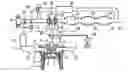
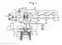
FIG. 1 is an overview of an internal combustion engine provided with an exhaust purification apparatus of the present invention.
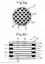
FIG. 2a is a front view of an S trap of a first embodiment of the present invention, while FIG. 2b is a longitudinal cross-sectional view of the same.
FIG. 3a is a front view of an S trap of a second embodiment of the present invention, while FIG. 3b is a longitudinal cross-sectional view of the same.
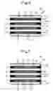
FIG. 4a is a front view of an S trap of a third embodiment of the present invention, while FIG. 4b is a longitudinal cross-sectional view of the same.
FIG. 5a is a front view of an S trap of a fourth embodiment of the present invention, while FIG. 5b is a longitudinal cross-sectional view of the same.
FIG. 6 is a longitudinal cross-sectional view of an S trap of still another embodiment of the present invention.
FIG. 7 is a longitudinal cross-sectional view of an S trap of still another embodiment of the present invention.
FIG. 8 is a longitudinal cross-sectional view of an S trap of still another embodiment of the present invention.
FIG. 9 is a longitudinal cross-sectional view of an S trap of still another embodiment of the present invention.
FIG. 10 is a cross-sectional view of an S trap of still another embodiment of the present invention.
BEST MODE FOR CARRYING OUT THE INVENTION
The embodiments of the present invention will be explained with reference to the drawings. FIG. 1 is an overview of an internal combustion engine provided with an exhaust purification apparatus of the present invention. The internal combustion engine shown in FIG. 1 is a 4-stroke compression ignition type internal combustion engine (so-called “diesel engine”), but the present invention can also be applied to another internal combustion engine, for example, a 4-stroke spark ignition type internal combustion engine (so-called “gasoline engine”).
In FIG. 1, 1 indicates an engine body, 2 indicates a cylinder block, 3 indicates a cylinder head, 4 indicates a piston, 5 indicates a combustion chamber, 6 indicates an electrical control type fuel injector, 7 indicates an intake valve, 8 indicates an intake port, 9 indicates an exhaust valve, and 10 indicates an exhaust port. The intake port 8 is connected through a corresponding intake tube 11 to a surge tank 12. The surge tank 12 is connected through an intake duct 13 and intercooler 14 to an outlet of a compressor 16 of a supercharger, for example, an exhaust turbocharger 15. An inlet of the compressor 16 is connected through an intake pipe 17 to an air cleaner 18. Inside the intake pipe 17, a throttle valve 20 driven by a step motor 19 is arranged. Further, in the intake pipe 17 upstream of the throttle valve 20, a mass flow detector 21 for detecting a mass flow of air taken into the combustion chamber 5 is arranged.
On the other hand, the exhaust port 10 is connected through an exhaust manifold 22 to an inlet of an exhaust turbine 23 of the exhaust turbocharger 15. An outlet of the exhaust turbine 23 is connected through an exhaust pipe 24 to a casing 26 housing an S trap 25. The S trap 25 will be explained in detail later. Further, the casing 26 is connected to a casing 28 housing a particulate filter 27. The particulate filter 27 is for trapping particulate matter of exhaust gas exhausted from the combustion chamber 5. Further, the casing 28 is connected to a casing 30 housing a NOx catalyst 29. The NOx catalyst 29 holds the nitrogen oxides (NOx) in the exhaust gas by absorption or adsorption when the air-fuel ratio of the exhaust gas flowing into it is lean and releases the held NOx and purifies the NOx by reduction by a reducing agent in the exhaust gas (for example, hydrocarbons or carbon monoxide) when the air-fuel ratio of the exhaust gas flowing into it is the stoichiometric air-fuel ratio or rich.
An exhaust pipe 31 connected to an outlet of the casing 30 and the intake pipe 17 downstream of the throttle valve 20 are connected to each other through an exhaust gas recirculation (below, referred to as a “EGR”) passage 32. Inside the EGR passage 32 is arranged an EGR control valve 34 driven by a step motor 33. Further, in the EGR passage 32 is arranged an intercboler 35 for cooling the EGR gas flowing through there. In the embodiment shown in FIG. 1, the engine cooling water is led into an intercooler 35 where engine cooling water cools the EGR gas.
On the other hand, the fuel injector 6 is connected through a fuel feed tube 36 to a fuel reservoir, that is, a so-called common rail 37. The common rail 37 is supplied with fuel from an electrical control type variable discharge fuel pump 38. The fuel supplied inside the common rail 37 is supplied through each fuel feed tube 36 to the corresponding fuel injector 6. The common rail 37 has a fuel pressure sensor 39 attached to it for detecting the fuel pressure inside it.
Next, the S trap of the first embodiment will be explained with reference to FIGS. 2a and b. Here, FIG. 2a is a front view of an S trap of a first embodiment, while FIG. 2b is a longitudinal cross-sectional view of the same. The S trap 25 of the present embodiment has a honeycomb-shaped base material 40 fabricated from cordierite or another porous material and a sulfur oxide trapping material (below, referred to as a “S trapping material”) 41 for trapping the sulfur oxides (SOx) in the exhaust gas. Further, inside the base material 40, partitions comprised of a porous material 42 define a plurality of passages (below, referred to as “cells”) 43, 44. These cells 43, 44 extend in parallel with each other. On the other hand, the S trapping material 41 includes at least one element selected from potassium (K), sodium (Na), cesium (Cs), and other such alkali metals, barium (Ba), calcium (Ca), and other such alkali earth metals, and lanthanum (La), yttrium (Y), and other such rare earths, and platinum or another precious metal catalyst carried diffused on at least the surface. It exhibits a strong basicity and traps SOx in the form of sulfuric acid ions SO42− or sulfates.
Further, the S trapping material 41 is arranged at several specific cells 43 among the cells 43 and 44 of the base material 40 (below, referred to as the “specific cells”) in a manner packing them so as to occupy the entire volumes of said specific cells 43. Here, in the example shown in FIGS. 2a and b, the specific cells are selected so that there are four specific cells 43 surrounding each other cell 44. That is, seen in FIG. 2a, every other cell 43 in the longitudinal direction and lateral direction is selected as a specific cell.
The S trap 25 is arranged in the casing 26 so that, for example, in FIG. 2b, the exhaust gas flows in from the end at the left side and the exhaust gas flows out from the end at the right side. For this reason, the exhaust gas reaching the S trap 25 basically flows into the cells 44 in which the S trapping material is not arranged and flows out through the insides of the cells 44 from the S trap. Here, the cells 43 in which the S trapping material 41 is arranged and the cells 44 in which it is not are separated by the partitions comprised of a porous material 42, so the SOx in the exhaust gas flowing into the cells 44 in which the S trapping material is not arranged can pass through the pores of the partitions 42 and reach the S trapping material 41. That is, the S trapping material 41 is arranged in a manner able to contact the exhaust gas inside the cells 44 separated by the partitions comprised of a porous material having permeability. Further, the SOx reaching the S trapping material 41 in this way is trapped by the S trapping material.
As in the first embodiment, if arranging the S trapping material 41 in the cells 43 in a form packed so as to occupy the entire volumes of the cells 43, the following effects are obtained. That is, in the past, an S trapping material was arranged in the cells in a manner coating the partition surfaces, but in this case, even if making the thickness of the S trapping material coated on the partition surfaces greater, that is, even if increasing the amount of S trapping material coated on the partition surfaces, if the amount ended up exceeding a certain amount, it had been believed that the amount of SOx which the S trapping material could trap would not increase. This is because the S trapping material only traps SOx at the surfaces or the parts close to the surfaces, so to increase the amount of SOx which the S trapping material can trap, it has been believed that it is necessary to not increase the amount of S trapping material coated on the partitions, but to enlarge the surface area of the S trapping material coated.
However, research by the inventors of this application found that while SOx is trapped at the surfaces of the S trapping material, the SOx trapped at the surfaces of the S trapping material gradually diffuses inside the S trapping material and is held in the S trapping material. That is, in the same way as in the past, when arranging the S trapping material in the cells in a form coated on the partition surfaces, if making the thickness of the S trapping material coated on the partition surfaces greater, that is, if increasing the amount of S trapping material coated on the partition surfaces, even if the surface area of the S trapping material is the same, it is learned that the amount of SOx which the S trapping material can trap increases.
In the above-mentioned embodiment of the present invention, the S trapping material is arranged as aggregates inside the cells in a form packed so as to occupy the entire volumes of the insides of the cells, so the amount of S trapping material used in the S trap as a whole becomes greater than the amount used in the past. At the very least, if viewed from the viewpoint of the thickness of the S trapping material arranged (coated) at the partition surfaces where the S trapping material should be arranged (coated), the thickness of the S trapping material of the present embodiment is much greater than the thickness of the past where it had been thought that even if made greater than this, the amount of SOx which the S trapping material can trap would not become greater. Further, if viewed from the viewpoint of the amount of S trapping material arranged (coated) per unit surface area of the partition surfaces where the S trapping material should be arranged (coated), the amount of S trapping material of the present embodiment is much greater than the amount of the past where it had been thought that even if made greater than this, the amount of SOx which the S trapping material can trap would not become greater. For this reason, according to the present embodiment, the amount of SOx which can be trapped by the S trap as a whole becomes much greater compared with the past.
Next, a second embodiment will be explained. An S trap of the second embodiment is shown in FIGS. 3a and b. Here, FIG. 3a is a front view of an S trap of a second embodiment, while FIG. 3b is a longitudinal cross-sectional view of the same. The base material 40 of the S trap 25 of the present embodiment is the same as that of the first embodiment. Further, in the present embodiment as well, the S trapping material 41 is arranged inside the cells 43 defined as “specific cells” in the first embodiment, but in the present embodiment, unlike the first embodiment, the S trapping material 41 is arranged inside the cells in a manner packed in the cells so as to leave spaces extending along the long axes of the cells 43 at the middle of the cells. That is, in the present embodiment, the S trapping material 41 is arranged in the cells in a manner packed so as to partially close the cells 43.
According to the second embodiment, the SOx in the exhaust gas flowing into the cells 44 where the S trapping material is not packed passes through the pores of the partitions 42 and reaches the S trapping material 41 where it is trapped in the S trapping material. The SOx in the exhaust gas flowing into the spaces extending along the centers of the S trapping material also is trapped by the S trapping material 41 while flowing through said spaces.
In the second embodiment as well, the S trapping material 41 is arranged as aggregates inside the cells 43, so the amount of S trapping material used in the S trap as a whole becomes greater than the amount used in the past. At the very least, if viewed from the viewpoint of the thickness of the S trapping material arranged (coated) at the partition surfaces where the S trapping material should be arranged (coated), the thickness of the S trapping material of the present embodiment is much greater than the thickness of the past, where it had been thought that even if made greater than this, the amount of SOx which the S trapping material can trap would not become greater. Further, if viewed from the viewpoint of the amount of S trapping material arranged (coated) per unit surface area of the partition surfaces where the S trapping material should be arranged (coated), the amount of S trapping material of the present embodiment is much greater than the amount of the past where it had been thought that even if made greater than this, the amount of SOx which the S trapping material can trap would not become greater. For this reason, according to the present embodiment, for the same reason as explained above, the amount of SOx which can be trapped by the S trap as a whole is much greater than the past.
Next, a third embodiment will be explained. The S trap of the third embodiment is shown in FIGS. 4a and b. Here, FIG. 4a is a front view of an S trap of the third embodiment, while FIG. 4b is a longitudinal cross-sectional view of the same. The base material 40 of the S trap 25 of the present embodiment is the same as that of the first embodiment. Further, in the present embodiment, in the cells 43 defined as the “specific cells” in the first embodiment, the S trapping material 41 is arranged only at one end regions (the regions of the left ends seen in FIG. 4b) in a manner packing said end regions to completely block them, while in the remaining cells 44, the S trapping material 41 is arranged only at the other end regions (the regions of the right ends seen in FIG. 4b) in a manner packing said end regions to completely block them.
In the third embodiment, the exhaust gas flows into the cells 44 where the S trapping material 41 is arranged at the downstream side (the right side in FIG. 4b when exhaust gas arrives from the left side in FIG. 4b) end regions, passes through the pores of the partitions around the cells 44, flows into the cells 43 where the S trapping material 41 is arranged at the upstream side (the left side in FIG. 4b when exhaust gas arrives from the left side in FIG. 4b) end regions, and flows out from the downstream side openings of said cells 43. Further, the SOx in the exhaust gas reaching the S trapping material 41 is trapped by the S trapping material while the exhaust gas flows in this way.
In the third embodiment as well, the S trapping materials are arranged as aggregates inside the cells, so the amount of S trapping material used in the S trap as a whole is greater than the amount used in the past. At the very least, if viewed from the viewpoint of the thickness of the S trapping material arranged (coated) at the partition surfaces where the S trapping material should be arranged (coated), the thickness of the S trapping material of the present embodiment is much greater than the thickness of the past, where it had been thought that even if made greater than this, the amount of SOx which the S trapping material can trap would not become greater. Further, if viewed from the viewpoint of the amount of S trapping material arranged (coated) per unit surface area of the partition surfaces where the S trapping material should be arranged (coated), the amount of S trapping material of the present embodiment is much greater than the amount of the past where it had been thought that even if made greater than this, the amount of SOx which the S trapping material can trap would not become greater. For this reason, according to this embodiment, for the same reason as explained above, the amount of SOx which can be trapped by the S trap as a whole is much greater than the past.
Next, a fourth embodiment will be explained. The S trap of the fourth embodiment is shown in FIGS. 5a and b. Here, FIG. 5a is a front view of an S trap of the fourth embodiment, while FIG. 5b is a longitudinal cross-sectional view of the same. The base material 40 of the S trap 25 of the present embodiment is the same as in the first embodiment. Further, in the present embodiment as well, the S trapping material 41 is arranged inside the cells 43 defined as “specific cells” in the first embodiment, but in the present embodiment, unlike the first embodiment, the S trapping material 41 is arranged at only the end regions at the two sides (regions at left ends and regions at right ends in view of FIG. 5b) in a manner packed so as to completely block the end regions.
In the fourth embodiment, the exhaust gas basically passes through the cells in which the S trapping material is not arranged, but at least part of the exhaust gas passes through the pores of the partitions 42, flows into the cells 43 where the S trapping material 41 is arranged, and flows through said cells 43 to reach the S trapping material 41, or passes through the pores of the partitions to reach the S trapping material 41 directly. Further, the SOx in the exhaust gas reaching the S trapping material 41 is trapped by the S trapping material. Of course, the SOx in the exhaust gas reaching the S trapping material 41 without passing through the partitions 42 from places directly exposed to the exhaust gas is also trapped by the S trapping material.
In the fourth embodiment as well, for the same reason as explained in relation to the third embodiment, the amount of SOx able to be trapped by the S trap as a whole is much greater compared with the past.
Note that in the fourth embodiment, nothing is arranged between the S trapping materials 41 arranged at the end regions of the two sides, but as shown in FIG. 6, it is also possible to arrange a large number of relatively small aggregates (for example, tablet shaped aggregates or pellet-shaped aggregates) 41A of the S trapping material between these S trapping materials 41 in a manner leaving spaces. According to this, the SOx in the exhaust gas flowing into the cells in which the S trapping materials 41, 41A are arranged can be reliably trapped.
Further, in the example shown in FIG. 6, as shown in FIG. 7, it is also possible to block the openings at the downstream side (the right side in FIG. 7 when exhaust gas arrives from the left side in FIG. 7) of several cells among the cells 44 where the S trapping material is not arranged by plugs 45. According to this, the exhaust gas flowing into the cells 44 blocked by the plugs 45 has to pass through the cells 43 where the S trapping materials 41, 41A are arranged, so a greater amount of SOx can be trapped.
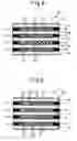
Further, as shown in FIG. 8, it is also possible to arrange porous S trapping material 41B packed between the S trapping materials 41 arranged at the end regions at the two sides. By this as well, it is possible to reliably trap the SOx in the exhaust gas flowing into the cells 43 where the S trapping materials 41, 41B are arranged.
Further, in the example shown in FIG. 8 as well, as shown in FIG. 9, it is also possible to block the openings at the downstream side (the right side in FIG. 9 when exhaust gas arrives from the left side in FIG. 9) of several cells among the cells 44 where the S trapping material is not arranged by plugs 45. According to this, a greater amount of SOx can be trapped.
Note that in the above-mentioned embodiments, so long as not interfering with the exhaust gas passing through the partitions and arriving at the S trapping material, in the same way as the past, it is also possible thinly coat the S trapping material on the partition surfaces.
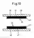
Further, in the above explanation, the present invention was explained with reference to examples of embodiments where the S trapping materials 41, 41A, 41B were arranged inside the cells of the honeycomb-shaped base material 40, but as another embodiment, there is also the embodiment shown in FIG. 10. That is, in the embodiment shown in FIG. 10, spaces 48 separated by partitions comprised of a porous material 47 are formed in the exhaust pipe 46. In these spaces, aggregates 41 of the S trapping material are arranged packed. In this embodiment as well, rather than use thin S trapping materials 41, aggregates are used and there is a large quantity of S trapping material, so for the same reason as explained above, the amount of SOx which can be trapped by the S trap 25 as a whole becomes greater than in the past. From this viewpoint, the present invention, broadly speaking, can be said to be one which forms spaces separated by partitions comprised of a porous material inside a passage through which exhaust gas flows (exhaust pipe) and arranges aggregates of an S trapping material in said spaces.
However, as explained above, by arranging the S trapping material as aggregates inside the S trap, the amount of SOx which the S trap can trap as a whole can be remarkably increased. Along with this, there is the advantage that the following treatment can be applied to the S trap. That is, as explained above, the SOx trapped at the surface of the S trapping material diffuses inside the S trapping material, so the SOx trapping rate at the surface of the S trapping material basically should be maintained at a high value. However, along with the elapse of time, this SOx trapping rate sometimes rapidly falls. At this time, if raising the temperature of the S trap in the state where the air-fuel ratio of the exhaust gas flowing into the S trap is maintained lean, the SOx trapping rate is restored.
That is, in the state where the air-fuel ratio of the exhaust gas is maintained lean, if raising the temperature of the S trap, the SOs present concentrated near the surface of the S trapping material diffuses toward the inside of the S trapping material so that the concentration of SOx inside the S trapping material becomes uniform. That is, the sulfates produced inside the S trapping material change from an unstable state concentrated near the surface of the S trapping material to a stable state uniformly diffused throughout the inside of the S trapping material. According to this, the SOx concentration falls near the surface of the S trapping material and therefore the SOx trapping rate is restored.
Therefore, in the above-mentioned embodiments, when the SOx trapping rate has fallen (for example, when the SOx trapping rate has fallen below a predetermined rate), it is also possible to treat the S trap to raise the temperature of the S trapping material. According to this, the SOx trapping rate can be restored and the amount of SOx which the S trap can trap as a whole can be further improved. Further, in addition to treatment to raise the temperature in accordance with the SOx trapping rate of the S trap, the treatment to raise the temperature may also be performed when the amount of exhaust gas flowing into the S trap exceeds a certain fixed amount (it can be said that the greater the amount of this exhaust gas, the greater the amount of SOx trapped in the S trap).
Note that although the present invention was explained in detail based on specific embodiments, a person skilled in the art can be modified, changed, etc. in various ways without departing from the claims and concept of the present invention.
Claims
1-16. (canceled)
17. A method for manufacturing a knuckle and hub assembly for a vehicle comprising the steps of:
providing a wheel hub having a flange portion with an outer flange surface and an inner flange surface;
securing a plurality of wheel bolts to the flange portion of the wheel hub;
connecting a knuckle component to the wheel hub to form the knuckle and hub assembly;
clamping the knuckle and hub assembly without attachment to the vehicle; and
refinishing the outer flange surface and the inner flange surface of the knuckle and hub assembly to minimize run-out while the knuckle and hub assembly is clamped without attachment to a vehicle.
18. The method of claim 17 further comprising the step of:
finishing the outer flange surface and inner flange surface prior to securing the plurality of wheel bolts to the wheel hub.
19. The method of claim 18 wherein the knuckle component is stationary and the wheel hub rotates during the refinishing of the knuckle and hub assembly.
20. The method of claim 19 wherein the refinishing of the outer flange and the inner flange surface reduces the run-out to 14 micrometers or less.
21. The method of claim 19 wherein the refinishing of the outer flange surface and the inner flange surface such that the co-planarness of the outer flange surface and the inner flange surface is 20 micrometers or less.
22. The method of claim 17 wherein a clamping fixture clamps the knuckle and hub assembly during the refinishing of the outer flange surface and the inner flange surface.
23. The method of claim 17 wherein a lathe refinishes the outer flange surface and the inner flange surface.
24. The method of claim 23 further comprising:
rotating the knuckle and hub assembly with respect to the lathe during the refinishing of the knuckle and hub assembly.
25. The method of claim 17 wherein the wheel hub has a relief channel disposed between the inner flange surface and the outer flange surface.
26. A method for manufacturing a knuckle and hub assembly comprising:
providing a wheel hub having a flange portion with an outer flange surface and an inner flange surface;
connecting a knuckle component to the wheel hub to form the knuckle and hub assembly;
clamping the knuckle component of the knuckle and hub assembly without attachment to the vehicle; and
rotating the wheel hub of the knuckle and hub assembly to finish the outer flange surface and the inner flange surface of the knuckle and hub assembly to minimize run-out while the knuckle and hub assembly is clamped without attachment to a vehicle.
27. The method of claim 26 wherein the knuckle and hub assembly is finished such that the outer flange surface and the inner flange surface have a co-planarness within 20 micrometers.
28. The method of claim 27 further comprising the step of:
securing the wheel bolts to the wheel hub prior to finishing the outer flange surface and the inner flange surface.
29. The method of claim 28 wherein the knuckle component has a plurality of apertures formed therein for attachment of the knuckle component to the vehicle.
30. The method of claim 29 further comprising the step of:
forming a relief channel in said flange portion between the inner flange surface and the outer flange surface, the relief channel having a plurality of wheel bolt receiving apertures formed therein for receipt of the wheel bolts therethrough.
31. The method of claim 26 wherein the knuckle component remains secured to the wheel hub during the finishing of the outer flange surface and the inner flange surface.
32. The method of claim 27 wherein the knuckle component is held stationary during finishing of the knuckle and hub assembly.
33. The method of claim 32 wherein a fixture having a lathe refinishes the outer flange surface and the inner flange surface.
34. The method of claim 32 wherein the wheel hub rotates with respect to the lathe.
35. A method for manufacturing a knuckle and hub assembly for a vehicle comprising:
providing a wheel hub having a neck portion and a flange portion, the flange portion having a flange face with an inner flange surface and an outer flange surface, and a relief channel disposed between the inner flange surface and the outer flange surface;
forming a plurality of bolt receiving apertures in the relief channel;
attaching a plurality of wheel bolts on the wheel hub;
assembling the wheel hub and a knuckle to form the knuckle hub assembly;
clamping the knuckle into a fixture incorporating a lathe;
final finishing the inner flange surface and the outer flange surface to reduce lateral run-out wherein the inner flange surface and the outer flange surface have a flatness of at least 20 micrometers.
36. The method for manufacturing the method of claim 35 wherein the knuckle is held stationary and the wheel hub is rotated during the final finishing of the outer flange surface and the inner flange surface.
Images & Drawings included:


Sources:
- United States Patent and Trademark Office - verify current appl. status at the USPTO↗
Similar patent applications:
- » 20100229530
Control device and control method for exhaust gas purification apparatus, and internal combustion engine exhaust gas purification apparatus - » 20100319316
Oxidation catalyst fault diagnosis unit and oxidation catalyst fault diagnosis method and internal combustion engine exhaust purification apparatus - » 20100319651
Temperature sensor plausibility diagnosis unit and plausibility diagnosis method and internal combustion engine exhaust purification apparatus - » 20140165539
Reducing agent supply apparatus and internal-combustion engine exhaust gas purification apparatus - » 10419884
Internal combustion engine exhaust gas purification apparatus, exhaust gas purification process and exhaust gas purification catalyst - » 10768141
Exhaust purification apparatus for internal combustion engine - » 20070051098
Regeneration controller for exhaust purification apparatus of internal combustion engine - » 20060137328
Exhaust purification method and exhaust purification apparatus of internal combustion engine - » 20060213188
Regeneration controller for exhaust purification apparatus of internal combustion engine - » 20070137180
Regeneration controller for exhaust purification apparatus of internal combustion engine
Recent applications in this class:
- » 20250269326 2025-08-28
EXHAUST PURIFICATION DEVICE - » 20250256243 2025-08-14
EXHAUST GAS PURIFICATION DEVICE - » 20250091004 2025-03-20
GASOLINE PARTICULATE FILTER - » 20250001360 2025-01-02
EMISSIONS TREATMENT ARTICLES WITH INORGANIC FILTRATION DEPOSITS AND CATALYTIC MATERIAL - » 20240269614 2024-08-15
PARTICULATE FILTER - » 20230302406 2023-09-28
EXHAUST GAS PURIFICATION CATALYST DEVICE - » 20230201771 2023-06-29
Composite structures, heater apparatus, fast light-off exhaust aftertreatment systems, and methods of manufacturing and using same - » 20220274060 2022-09-01
Catalytic converter - » 20200122086 2020-04-23
Emission control system - » 20180050307 2018-02-22
Exhaust purification device
Recent applications for this Assignee:
- » 20250269863 2025-08-28
CONTROL DEVICE FOR VEHICLE - » 20250260261 2025-08-14
POWER STORAGE SYSTEM - » 20250256722 2025-08-14
CONTROL DEVICE FOR VEHICLE - » 20250250947 2025-08-07
INTERNAL COMBUSTION ENGINE CONTROL DEVICE - » 20250244145 2025-07-31
POINT CLUSTERING BASED ON ROADWAYS - » 20250242786 2025-07-31
METHOD FOR DISCRETE HANDLING OF BRAKE CONTROL BETWEEN DRIVER AND MECHANICAL SYSTEM - » 20250236267 2025-07-24
VEHICLE - » 20250227664 2025-07-10
APPARATUS AND METHODS FOR IMPROVING MULTI-SIM DEVICES PERFORMANCE AND OPERATION - » 20250206097 2025-06-26
STABILIZER CONTROL DEVICE - » 20250196796 2025-06-19
SUPPORT MECHANISM FOR CURTAIN SHIELD AIRBAG