Fuel pump set
US20090151704A1
2009-06-18
12/120,913
2008-05-15
✅ Patent granted
US 7,814,891 B2
2010-10-19
-
-
Stephen K Cronin | Arnold Castro
2028-12-30
Abstract:
A fuel pump set includes a cam shaft with a cam; a bridge contacting the cam shaft; a head cover attaching the bridge to the cam shaft; and a fuel pump, disposed in the bridge and operable by the cam. The bridge may include two supports, each contacting the cam shaft. One support may have a supporting face, with a shape corresponding to the shape of the cam shaft, with the cam shaft disposed therein. The two supports together may define a shape that widens downward. One support may narrow downward. The set may also include a rod extending from the fuel pump to the cam, reciprocated by the cam. The bridge may include a sealing face supported by the head cover, a groove for preventing rotation of the fuel pump, and/or a breather. The head cover may include an opening in which the fuel pump is disposed.
Inventors:
- Jongsub Lee 1 🇰🇷 Yongin-city, South Korea
- Il Suk Yang 2 🇰🇷 Suwon-city, South Korea
- Jongsub Lee 1 🇰🇷 Yongin, South Korea
- Il Suk Yang 1 🇰🇷 Suwon, South Korea
Assignee:
- Kia Motors Corporation 8,327 🇰🇷 Seoul, South Korea
- Hyundai Motor Company 20,646 🇰🇷 Seoul, South Korea
Interested in similar patents?
Get notified when new applications in this technology area are published.
Classification:
F02M59/102 » CPC main
Pumps specially adapted for fuel-injection and not provided for in groups -, e.g. rotary cylinder-block type of pumps of reciprocating-piston or reciprocating-cylinder type characterised by the piston-drive Mechanical drive, e.g. tappets or cams
F02M59/48 » CPC further
Pumps specially adapted for fuel-injection and not provided for in groups -, e.g. rotary cylinder-block type of pumps; Details, components parts, or accessories not provided for in, or of interest apart from, the apparatus of groups - ; Pumps having transducers, e.g. to measure displacement of pump rack or piston Assembling; Disassembling; Replacing
F04B1/0404 » CPC further
Multi-cylinder machines or pumps characterised by number or arrangement of cylinders having cylinders in star- or fan-arrangement Details or component parts
F04B1/0413 » CPC further
Multi-cylinder machines or pumps characterised by number or arrangement of cylinders having cylinders in star- or fan-arrangement; Details or component parts Cams
F04B17/05 » CPC further
Pumps characterised by combination with, or adaptation to, specific driving engines or motors driven by internal-combustion engines
F04B53/16 » CPC further
Component parts, details or accessories not provided for in, or of interest apart from, groups - or - Casings; Cylinders; Cylinder liners or heads; Fluid connections
F02M37/06 IPC
Apparatus or systems for feeding liquid fuel from storage containers to carburettors or fuel-injection apparatus; Arrangements for purifying liquid fuel specially adapted for, or arranged on, internal-combustion engines; Feeding by means of driven pumps mechanically driven
F02M59/10 IPC
Pumps specially adapted for fuel-injection and not provided for in groups -, e.g. rotary cylinder-block type of pumps of reciprocating-piston or reciprocating-cylinder type characterised by the piston-drive
F02M39/00 IPC
Fuel-injection apparatus
F02M39/00 IPC
Arrangements of fuel-injection apparatus with respect to engines; Pump drives adapted to such arrangements
Description
CROSS-REFERENCE TO RELATED APPLICATION
This application claims priority to, and the benefit of Korean Patent Application No. 10-2007-0130416, filed in the Korean Intellectual Property Office on Dec. 13, 2007, the entire contents of which are incorporated herein by reference.
BACKGROUND OF THE INVENTION
(a) Field of the Invention
The present invention relates to a fuel pump set, and more particularly relates to a coupling structure of a fuel pump.
(b) Description of the Related Art
A fuel pump can be driven by a camshaft in a gasoline direct injection (GDI) engine. Fuel is usually pumped in one of two ways. The first creates pressure in a cylinder of the pump using torque of the camshaft. This method makes it difficult to position the pump, and is costly. The other way of pumping fuel using a reciprocating rod, and a follower connected to the camshaft. This method makes it easy to position the pump and is inexpensive, but operating stability is low.
The above information disclosed in this Background section is only for enhancement of understanding of the background of the invention and therefore it may contain information that does not form the prior art that is already known in this country to a person of ordinary skill in the art.
SUMMARY OF THE INVENTION
A fuel pump set includes a cam shaft; a cam on the cam shaft, a bridge contacting the cam shalt; a head cover attaching the bridge to the cam shaft; and a fuel pump, disposed in the bridge and operable by the cam.
The bridge may include a first and a second support, each contacting the cam shaft. The first support may have a supporting face, with a shape corresponding to the shape of the cam shaft, such that the cam shaft is disposed therein. The first support and the second support together may define a shape that widens downward. The first support may define a shape that narrows downward.
The fuel pump set may also include a rod extending from the fuel pump to the cam, reciprocated by the cam.
The bridge may include a sealing face supported by the head cover. The bridge may include a groove for preventing rotation of the fuel pump. The bridge may include a breather. The head cover may include an opening in which the fuel pump is disposed.
BRIEF DESCRIPTION OF THE DRAWINGS
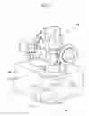
FIG. 1 is a partial perspective view of a fuel pump set according to an exemplary embodiment of the present invention.
FIG. 2A is a side view of the bridge shown in FIG. 1.
FIG. 2B is a front view of the bridge of FIG. 2A.
FIG. 2C is a sectional perspective view of the bridge of FIG. 2A.
FIG. 3 is a partial perspective view of a bridge and a camshaft shown in FIG. 1.
FIG. 4 is a partial sectional perspective view of a head cover shown in FIG. 1.
FIG. 5 is a partial cross-sectional view of the fuel pump set of FIG. 1.
REFERENCE NUMERALS
100: fuel pump
105: head cover
110: bridge
115: cam shaft
120: cam
200: supporting face
202a: first support
202b: second support
204: fitting hole
205: fixing groove
210, 415: fixing hole
215: breather
220: sealing face
222: groove for preventing rotation
405, 410: gasket rail
420: opening
500, 505: gasket
510: cylinder head
515: rod
520: spring
525: inlet
530: outlet
535: follower
DETAILED DESCRIPTION OF PREFERRED EMBODIMENTS
The present invention will be described more fully hereinafter with reference to the accompanying drawings, in which exemplary embodiments of the invention are shown. As those skilled in the art will realize, the described embodiments may be modified in various different ways, all without departing from the spirit or scope of the present invention.
Referring to FIG. 1, in some embodiments, a fuel pump set includes a cam 120 on a camshaft 115, a bridge 110, a head cover 105, and a fuel pump 100. A lower end of the bridge 110 contacts the camshaft 115. The bridge 110 is fixed securely to the camshaft 115 by the head cover 105. The fuel pump 100 is disposed in an upper portion of the bridge 110. The fuel pump 100 is driven by a rod 515 (FIG. 5) and a follower 535 (FIG. 5) that are reciprocated by the cam 120.
Referring to FIG. 2A, in some-embodiments, the bridge 110 includes a first support 202a, which narrows from top to bottom. Accordingly, the bridge 110 is light. A supporting face 200 at the bottom of the first support 202a is circular, and the camshaft 115 is situated within the supporting face 200.
As shown in FIG. 2B, in some embodiments, the bridge 110 also includes a second support 202b. The supports 202a, 202b may be trapezoidal, and widen from top to bottom. Accordingly, the coupling structure of the bridge 110 and the camshaft 115 is secure.
As shown in FIG. 2C, the bridge 110 may further include a fitting hole 204 into which the rod 515 (FIG. 5) and the follower 535 (FIG. 5) of the fuel pump 100 are disposed. A breather 215, a groove 222 for preventing rotation, and a fixing groove 205 are also provided on the bridge 110. Also, a fixing hole 210 is provided near the bottom of the bridge 110. The bridge 110 can be bolted to a cylinder head 510 (FIG. 5) through the fixing hole 210. The breather 215 is a pathway that exhausts pressure from inside the head cover 105 (FIG. 5). The groove 222 prevents rotation of the fuel pump 100. A fixing groove 205 is provided near the top of the bridge 110. The fuel pump 100 can be bolted to the fixing groove 205. A sealing face 220 is defined at an edge of the bridge 110. The head cover 105 securely supports the sealing face 220 in a direction of the cylinder head 510 (FIG. 5).
As shown in FIG. 3, the camshaft 115 is disposed in, and rotates within, the supporting face 200 (FIG. 2A). The camshaft 115 is fixed securely by the bridge 110.
Referring to FIG. 4, an opening 420 is provided in the head cover 105. The bridge 110 (FIG. 5) protrudes out of the head cover 105 through the opening 420. A first gasket rail 405 is formed corresponding to a lower edge of the head cover 105. A first gasket (500, FIG. 5) is disposed in the first gasket rail 405. A second gasket rail 410 is formed corresponding to the opening 420 of the inner side of the head cover 105. A second gasket (505, FIG. 5) is disposed in the second gasket rail 410. A fixing hole 415 is formed in one side of an edge of the head cover 105. The head cover 105 is fixed securely to the cylinder head (510, FIG. 5) by screwing a bolt (not shown) through the fixing hole 415.
As shown in FIG. 5, the camshaft 115 is disposed at an upper face of the cylinder head 510. The bridge 110 is installed on the camshaft 115. The fuel pump 100 is disposed in an upper end face of the bridge 110. An inlet 525 for fuel entry and an outlet 530 for fuel exit are formed in the fuel pump 100. The rod 515 is disposed in the fuel pump 100, through the fitting hole 204 of the bridge 110. The follower 535 is disposed at the end of the rod 515. The follower 535 and the rod 515 reciprocate vertically by the cam 120. A spring 520 is disposed around the rod 515 to help the rod 515 vertically reciprocate.
A lower portion of the head cover 105 is fixed to the cylinder head 510, and the head cover 105 securely supports the bridge 110 in a direction of the camshaft 115. Accordingly, the bridge 110 is supported by the head cover 105.
The first gasket 500 is interposed between the head cover 105 and the cylinder head 510, and the second gasket 505 is interposed between the head cover 105 and the sealing face 220 of the bridge 110.
While this invention has been described in connection with what is presently considered to be practical exemplary embodiments, it is to be understood that the invention is not limited to the disclosed embodiments, but, on the contrary, is intended to cover various modifications and equivalent arrangements included within the spirit and scope of the appended claims.
Claims
What is claimed is:1. A fuel pump set, comprising:
a cam shaft;
a cam disposed on the cam shaft;
a bridge contacting the cam shaft;
a head cover attaching the bridge to the cam shaft; and
a fuel pump, disposed in the bridge and operable by the cam.
2. The fuel pump set of claim 1, wherein the bridge comprises a first support contacting the cam shaft, and a second support contacting the cam shaft.
3. The fuel pump set of claim 2, wherein the first support comprises a supporting face, comprising a shape corresponding to a shape of the cam shalt, such that the cam shaft is disposed therein.
4. The fuel pump set of claim 2, wherein the first support and the second support define a shape that widens downward.
5. The fuel pump set of claim 2, wherein the first support defines a shape that narrows downward.
6. The fuel pump set of claim 1, further comprising a rod extending from the fuel pump to the cam, reciprocated by the cam.
7. The fuel pump set of claim 1, wherein the bridge comprises a sealing face supported by the head cover.
8. The fuel pump set of claim 1, wherein the bridge comprises a groove for preventing rotation of the fuel pump.
9. The fuel pump set of claim 1, wherein the bridge comprises a breather.
10. The fuel pump set of claim 1, wherein the head cover comprises an opening in which the fuel pump is disposed.
Images & Drawings included:


Sources:
- United States Patent and Trademark Office - verify current appl. status at the USPTO↗
Similar patent applications:
- » 20070020131
Set of piston type fuel pumps for internal combustion engines with direct fuel injection - » 20090272366
Internal combustion engine set up method and fuel pump having installation assist mechanism - » 20140127039
ALCOHOL FUEL-POWERED ELECTRIC PUMP AND SETTING METHOD FOR SAME - » 20210215127
METHOD FOR MANUFACTURING ASSEMBLY, PARTS SET, METHOD FOR MANUFACTURING FUEL INJECTION PUMP, AND FUEL INJECTION PUMP - » 20050158180
Method for setting the feed rate of a fuel pump unit, which sucks up fuel from a fuel tank, and fuel pump unit for the method - » 20080229726
Two-displacement setting variable displacement pump used as engine over-thrust protection with fuel system thermal benefit
Recent applications in this class:
- » 20240337233 2024-10-10
PUMP ACTUATOR WITH IMPROVED FATIGUE LIFE - » 20240309835 2024-09-19
ROLLER TAPPET ASSEMBLY - » 20240018925 2024-01-18
STAMPED PUMP ACTUATOR AND METHOD OF ASSEMBLING SAME - » 20230213012 2023-07-06
Fuel pump devices, systems, and methods - » 20230213011 2023-07-06
Pump housing with relief cut for lobe clearance - » 20230213010 2023-07-06
High-pressure fuel pump - » 20230167794 2023-06-01
SLIDING CAM FOLLOWER - » 20230068282 2023-03-02
Cam, fuel injection pump, and engine - » 20230066007 2023-03-02
Tappet for acting on a pump piston of a high-pressure fuel pump - » 20230003183 2023-01-05
TAPPET ROLLER ASSEMBLY
Recent applications for this Assignee:
- » 20250293967 2025-09-18
VEHICLE CONTROL APPARATUS AND METHOD THEREOF - » 20250293557 2025-09-18
MOTOR WITH A COOLING STRUCTURE - » 20250293373 2025-09-18
BATTERY ASSEMBLY - » 20250293361 2025-09-18
FUEL CELL POWER GENERATION MODULE - » 20250293308 2025-09-18
ELECTRODE ASSEMBLY AND ALL-SOLID STATE BATTERY INCLUDING THE SAME - » 20250292638 2025-09-18
SYSTEM AND METHOD FOR MONITORING POWER OF A VEHICLE - » 20250292590 2025-09-18
METHOD AND APPARATUS FOR CONTEXT-RECOGNITION OBJECT ACTION PREDICTION AND PATH PLANNING FOR AUTONOMOUS VEHICLES BASED ON PEDESTRIAN MOTION PREDICTION - » 20250290600 2025-09-18
PRESSURE VESSEL - » 20250289441 2025-09-18
METHOD AND APPARATUS FOR CALIBRATING ORIENTATION ANGLE OF VEHICLE SENSOR - » 20250289422 2025-09-18
SYSTEM AND METHOD FOR GENERATING EMERGENCY COLLISION AVOIDANCE STRATEGY FOR A VEHICLE