Test method for a variable capacitance measuring system
US20090167320A1
2009-07-02
11/630,989
2005-07-07
✅ Patent granted
US 7,728,603 B2
2010-06-01
WO; PCT/FR2005/050548; 20050707
WO; WO2006/008417; 20060126
Timothy J Dole
2027-05-18
Abstract:
A method for testing a variable capacitance measurement system including a fixed voltage source, a variable capacitance sensor, and a circuit to process information output by this sensor. The method connects an electrically controllable electronic simulation device to replace the variable capacitance sensor, models the electrophysical behaviour of the sensor, and tests the system.
Inventors:
- Marc Belleville 10 🇫🇷 Saint-Egreve, France
- Nicolas Delorme 9 🇫🇷 Grenoble, France
- Cyril Condemine 6 🇫🇷 Grenoble, France
- Marc Belleville 7 🇫🇷 St. Egreve, France
Assignee:
- Commissariat A L'Energie Atomique 1,591 🇫🇷 Paris, France
Interested in similar patents?
Get notified when new applications in this technology area are published.
Classification:
G01D18/00 » CPC main
Testing or calibrating apparatus or arrangements provided for in groups -
G01R27/2605 » CPC further
Arrangements for measuring resistance, reactance, impedance, or electric characteristics derived therefrom; Measuring real or complex resistance, reactance, impedance, or other two-pole characteristics derived therefrom, e.g. time constant; Measuring inductance or capacitance; Measuring quality factor, e.g. by using the resonance method; Measuring loss factor; Measuring dielectric constants ; Measuring impedance or related variables Measuring capacitance
G01R35/00 IPC
Testing or calibrating of apparatus covered by the other groups of this subclass
G01P15/125 » CPC further
Measuring acceleration; Measuring deceleration; Measuring shock, i.e. sudden change of acceleration by making use of inertia forces using solid seismic masses with conversion into electric or magnetic values by capacitive pick-up
G01R27/26 IPC
Arrangements for measuring resistance, reactance, impedance, or electric characteristics derived therefrom; Measuring real or complex resistance, reactance, impedance, or other two-pole characteristics derived therefrom, e.g. time constant Measuring inductance or capacitance; Measuring quality factor, e.g. by using the resonance method; Measuring loss factor; Measuring dielectric constants ; Measuring impedance or related variables
Description
TECHNICAL DOMAIN
This invention relates to a method of testing a variable capacitance measurement system.
The domain of the invention is microsystems comprising a capacitive sensor and a circuit to process information output by this sensor.
STATE OF PRIOR ART
Such microsystems with capacitive sensor are only partially tested in known art because their operation cannot be simulated with a sufficiently high resolution. There is thus an omission in methods of testing them, such that:
-
- Firstly, a purely electrical test is carried out not taking account of the sensor to check operation, and then
- the assembly, in other words the sensor part combined with the circuit processing information output by the sensor, is tested.
The disadvantage of such a method is that the test of the assembly is distorted by errors caused by lack of precise knowledge firstly of the electromechanical characteristics of the sensor and secondly of the signal to be measured.
The purpose of the invention is a test method overcoming this omission.
PRESENTATION OF THE INVENTION
The invention relates to a method for testing a variable capacitance measurement system comprising a voltage source, a variable capacitance sensor and a circuit to process information output by this sensor, characterised in that it comprises:
-
- a step to connect an electrically controllable electronic emulation device to replace the variable capacitance sensor, and thus present a measurable magnitude to the processing circuit,
- a step to model the electrophysical behaviour of this sensor,
- a step to test the system.
Advantageously, the method according to the invention includes the following during the connection step:
-
- a step in which a fixed capacitor is connected between the voltage source and the processing circuit, and
- a step in which a variable voltage source is connected as the voltage source to emulate a variation in the capacitance of said sensor, by means of variations of the voltage applied to this capacitor.
Advantageously, the value of the fixed capacitor is approximately equal to the capacitance of the sensor at rest.
The method according to the invention overcomes uncertainties related to the sensor (precise electromechanical characteristics or even just availability) and to the phenomenon to be measured (amplitude and frequency), and calibration of the machine that generates this phenomenon during the functional verification phase of the microsystem setting, or even purely electrical sorting of components after manufacture.
For example, the method according to the invention is applicable to the case of a capacitive accelerometer with a resolution better than 16 bits (˜1.5×10⁻³%) whereas the resolution of test devices according to prior art, for example vibrating bridges, does not exceed 12 bits (2.5×10⁻²%). The verification of the performances of a 16-bit accelerometer, for which the full scale capacitance variation is 1 pF, creates capacitance variations with a resolution of the order of 15 atofarad (15×10−18 Farad), whereas a vibrating bridge with a precision of 12 bits only provides a resolution of the order of 250 atoFarad.
BRIEF DESCRIPTION OF THE DRAWINGS
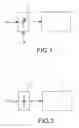
FIG. 1 illustrates the block diagram for a capacitive measurement system in normal mode.
FIG. 2 illustrates the block diagram for such a measurement microsystem in test mode, using the method according to the invention.
FIGS. 3 to 5 illustrate an example embodiment of the test method according to the invention.
FIG. 6 illustrates another example embodiment of the test method according to the invention in normal mode.
FIG. 7 illustrates an example embodiment of a capacitive sensor emulation device, the processing circuit not being shown.
DETAILED PRESENTATION OF PARTICULAR EMBODIMENTS
The method according to the invention is a test method for a variable capacitance measurement microsystem. Conventionally, such a microsystem comprises a fixed voltage source, a variable capacitance sensor and a circuit for processing information output by this sensor.
FIG. 1 thus illustrates an acceleration measurement microsystem comprising a capacitive sensor 10 and a processing circuit 11 used to measure the values of the capacitance of the sensor in a normal operating mode, VC being a constant excitation current and AP a physical acceleration.
In the method according to the invention, a fixed capacitor is connected between the voltage source and the processing circuit, this voltage source being a variable voltage source.
FIG. 2 thus illustrates the transformation of the microsystem illustrated in FIG. 1 in test mode. The capacitive sensor 10 is replaced by a fixed capacitor 12 integrated into the circuit or external to it. The constant excitation voltage VC and the physical acceleration AP are replaced by a variable excitation voltage VV. This excitation voltage VV is calculated so that the charge presented to the processing circuit 11 in test mode is identical to the charge in normal mode for a given constant excitation voltage VC and physical acceleration AP.
The method according to the invention can simulate a sensor that cannot be used either because it is unavailable, or because it cannot be operated to its limits.
Although it is easy to simulate variations in the voltage or current, it is difficult to simulate variations in the capacitance, particularly because the processing circuit must not be modified because it has to be tested in its initial state. Thus, the capacitive sensor 10 is replaced by a fixed capacitor 12 with a value approximately equal to the value of the capacitive sensor at rest so as to maintain a capacitive behaviour, variations in the capacitance then being emulated by means of voltage variations applied to this capacitor, to assure that the device according to the invention has a genuinely capacitive behaviour.
As a result of these characteristics, the resolution is transferred from the capacitances domain to the voltages domain, in which there is no problem in achieving very high precision levels.
More generally, the purpose of the invention is to delay variations in a physical parameter of a sensitive element (capacitor, resistance, inductance) on voltage or current variations that are simpler to obtain and that can be more precise.
In the example illustrated in FIG. 2, the processing circuit 11 can be used to measure capacitance values of the sensor through a measurement of the charge at constant charging voltage. The variation in the capacitance related to the variation in acceleration then varies the charge. The sensor can be replaced by an emulation device, in this case composed of a constant capacitance, the charge voltage varying so as to produce a variation of the charge Q (Q=CV) corresponding to the original acceleration variation. The emulation device can then produce the same effect as seen from the processing circuit 11 as the real sensor to which a given acceleration is applied, by an appropriate voltage control.
FIG. 3 illustrates one example embodiment of the method according to the invention. The two operating modes (normal mode and test mode) are selected using switches 20, 21, 24-27. V1 is a constant voltage and V2 is a variable voltage. An operational amplifier 30 is arranged at the output, a capacitor C1 being connected between its negative input and its output. Normal mode is activated when the test signal that controls switches 21, 24 and 26 is valid and test mode is activated when the test signal that controls switches 20, 25 and 27 is valid. C1 is the capacitive sensor 10 in FIG. 1. C2 is the constant capacitance 12 in FIG. 2. The output from the operational amplifier will be the image (by integration on Ci) of the charge stored by C1 or C2 as a function of the state of switches 20, 21, 24-27.
Operation of the processing circuit in normal mode, in other words not in test mode, is illustrated in FIG. 4. The capacitance C1 of the sensor is variable and it is evaluated by integrating the charge contained in it when a constant voltage V1 is applied to it. Consider two successive non-overlapping clock phases Phi1 and phi2. When the switches 22 and 29 validated by phase phi1 close, capacitor C1 is charged at constant voltage V1. Later, when switches 23 and 28 validated by phase phi2 close, the charge contained on C1 is transferred to the integration capacitor Ci, producing a variation of the output voltage VS equal to ΔVout=C1/Ci.Vc.
During operation in test mode illustrated in FIG. 5, the value of capacitor C2 is chosen equal to the value of capacitor C1 at rest (at zero acceleration) so as to optimise reproduction of the behaviour of the circuit in normal mode. V2 is then chosen as follows to emulate a variation in the sensor capacitance ΔC1max (and especially the corresponding charge):
V2DC=V1DCand
C2.ΔV2max=ΔC1max.V1
In one example embodiment illustrated in FIG. 6, the capacitive sensor comprises two capacitors (module 35), each having its own control circuit and test circuit. These two capacitors vary in opposite directions depending on the acceleration. The processing circuit evaluates the difference in capacitances of the sensor by measuring the charge at constant charging voltage. The variation in the capacitance related to the variation in the acceleration then causes a variation in the charge. The voltages 36 are fixed measurement voltages. All <<phi>> values are commands applied to the switches at different moments.
FIG. 7 illustrates an example embodiment of an electrical emulation device of this capacitive sensor, that replaces module reference 35 in FIG. 6. The integrated capacitors 37 are fixed and the charge voltages 38 are variable. The <<test>> and <<testb>> signals control either the connection of the sensor to the processing circuit (connection of signals <<topadccp>> to <<tomodccp>>, <<topadccn>> to <<tomodccn>>, <<topadcom>> to <<tomodcom>>) and disconnection of the electrical emulation device from this same circuit, or the inverse, namely disconnection of the sensor and connection of the electrical emulation device.
Claims
1-3. (canceled)
4. A method for testing a variable capacitance measurement system including a voltage source, a variable capacitance sensor, and a processing circuit to process information output by the sensor, the method comprising:
connecting an electrically controllable electronic simulation device to replace the variable capacitance sensor;
modeling electrophysical behaviour of the sensor; and
testing the system.
5. A method according to claim 4, the connecting comprising:
connecting a fixed capacitor between the voltage source and the processing circuit; and
connecting a variable voltage source as the voltage source to simulate a variation in the capacitance of the sensor, by variations of the voltage applied to the capacitor.
6. A method according to claim 5, wherein a value of the fixed capacitor is approximately equal to the capacitance of the sensor at rest.
Images & Drawings included:


Sources:
- United States Patent and Trademark Office - verify current appl. status at the USPTO↗
Recent applications in this class:
- » 20250251263 2025-08-07
ACTIVE FOOTWEAR SENSOR CALIBRATION - » 20250251262 2025-08-07
TOOL MATCHING USING DIGITAL TWINS - » 20250216231 2025-07-03
SYSTEM REPRESENTATION AND METHOD OF USE - » 20250198811 2025-06-19
CALIBRATION METHOD AND CALIBRATION APPARATUS FOR ANGLE SENSOR - » 20250198810 2025-06-19
IDENTIFICATION AND CORRECTION OF ANOMALOUS SENSOR BEHAVIOR USING CALIBRATION HARMONIZATION - » 20250172418 2025-05-29
SYSTEMS, APPARATUS, AND RELATED METHODS FOR VEHICLE SENSOR CALIBRATION - » 20250146847 2025-05-08
CONTROL METHOD AND DEVICE, AERIAL VEHICLE, MOVABLE PLATFORM, AND STORAGE MEDIUM - » 20250146846 2025-05-08
FIELD DEVICE AND DIAGNOSTIC METHOD - » 20250146845 2025-05-08
METHOD AND DEVICE OF AMPLITUDE-PHASE INCONSISTENCY IN-SITU CORRECTION FOR THE MULTI-CHANNEL CAPACITIVE SENSOR - » 20250137822 2025-05-01
METHOD, APPARATUS AND COMPUTER-READABLE MEDIUM FOR MONITORING ABNORMAL CONDITION BASED ON MULTI SENSOR DEPENDING ON THE OPERATION MODE
Recent applications for this Assignee:
- » 20200088702 2020-03-19
Method of calibrating an electronic nose - » 20190096671 2019-03-28
Method of producing an element of a microelectronic device - » 20190047870 2019-02-14
Method for preparing silicon and/or germanium nanowires - » 20150365098 2015-12-17
Systems and methods for implementing error-shaping alias-free asynchronous flipping analog to digital conversion - » 20150050304 2015-02-19
CD4+ T survivin epitopes and uses thereof - » 20150034147 2015-02-05
Photovoltaic module comprising a localised spectral conversion element and production process - » 20150031580 2015-01-29
Method for the quantitative assessment of global and specific DNA repair capacities of at least one biological medium, and the applications therefor - » 20140341565 2014-11-20
Device for measurement of the profile of very short duration single pulses - » 20140241554 2014-08-28
Systems, devices, and methods for continuous-time digital signal processing and signal representation - » 20140231661 2014-08-21
Two-dimensional detection system for neutron radiation in the field of neutron scattering spectrometry