Lateral light-emitting diode backlight module
US20090168403A1
2009-07-02
12/344,108
2008-12-24
✅ Patent granted
US 7,919,789 B2
2011-04-05
-
-
Davienne Monbleau | Monica D Harrison
2029-08-24
Abstract:
A lateral light-emitting diode backlight module includes a base, a circuit board, and at least a light emitting diode wherein the base having a heat conductor, the circuit board having a conductive pad formed on a surface thereof, and the circuit board disposed on the heat conductor and connected to the heat conductor. Each light emitting diode comprising a substrate, a heat sink fastened to the substrate and connected to the heat conductor, an LED chip disposed on the heat sink and emits light laterally, and a pin mounted on the substrate and extended to the conductive pad of the circuit board.
Inventors:
- Yi-Tsuo WU 9 🇹🇼 Jhonghe City, Taiwan
- Hsiao-Chiao LI 5 🇹🇼 Sinjhuant City, Taiwan
- Chia-Hsien Chang 5 🇹🇼 Yongjing Township, Taiwan
- Yi-Tsuo Wu 8 🇹🇼 Jhonghe, Taiwan
- Hsiao-Chiao Li 4 🇹🇼 Sinjhuant, Taiwan
- Chia-Hsien Chang 2 🇹🇼 Yongjing Township, Changhua County, Taiwan
Assignee:
- Everlight Electronics Co., Ltd. 8 🇹🇼 Tu Chen, Taipei Hsien, Taiwan
Interested in similar patents?
Get notified when new applications in this technology area are published.
Classification:
H05K1/021 » CPC main
Printed circuits; Details; Thermal arrangements, e.g. for cooling, heating or preventing overheating; Cooling of mounted components Components thermally connected to metal substrates or heat-sinks by insert mounting
H05K1/021 » CPC main
Printed circuits; Details; Thermal arrangements, e.g. for cooling, heating or preventing overheating; Cooling of mounted components Components thermally connected to metal substrates or heat-sinks by insert mounting
F21K9/68 » CPC further
Light sources using semiconductor devices as light-generating elements, e.g. using light-emitting diodes [LED] or lasers; Optical arrangements integrated in the light source, e.g. for improving the colour rendering index or the light extraction Details of reflectors forming part of the light source
F21V29/505 » CPC further
Protecting lighting devices from thermal damage; Cooling or heating arrangements specially adapted for lighting devices or systems; Cooling arrangements characterised by the adaptation for cooling of specific components of reflectors
F21V29/70 » CPC further
Protecting lighting devices from thermal damage; Cooling or heating arrangements specially adapted for lighting devices or systems; Cooling arrangements characterised by passive heat-dissipating elements, e.g. heat-sinks
F21V29/86 » CPC further
Protecting lighting devices from thermal damage; Cooling or heating arrangements specially adapted for lighting devices or systems characterised by the material Ceramics or glass
F21V29/87 » CPC further
Protecting lighting devices from thermal damage; Cooling or heating arrangements specially adapted for lighting devices or systems characterised by the material Organic material, e.g. filled polymer composites; Thermo-conductive additives or coatings therefor
F21V29/89 » CPC further
Protecting lighting devices from thermal damage; Cooling or heating arrangements specially adapted for lighting devices or systems characterised by the material Metals
H05K1/182 » CPC further
Printed circuits; Printed circuits structurally associated with non-printed electric components associated with components mounted in the printed circuit board, e.g. insert mounted components [IMC]
H05K1/182 » CPC further
Printed circuits; Printed circuits structurally associated with non-printed electric components associated with components mounted in the printed circuit board, e.g. insert mounted components [IMC]
H05K3/0061 » CPC further
Apparatus or processes for manufacturing printed circuits; Laminating printed circuit boards onto other substrates, e.g. metallic substrates onto a metallic substrate, e.g. a heat sink
H05K3/0061 » CPC further
Apparatus or processes for manufacturing printed circuits; Laminating printed circuit boards onto other substrates, e.g. metallic substrates onto a metallic substrate, e.g. a heat sink
H05K2201/10106 » CPC further
Indexing scheme relating to printed circuits covered by; Details of components or other objects attached to or integrated in a printed circuit board; Types of components Light emitting diode [LED]
H05K2201/10106 » CPC further
Indexing scheme relating to printed circuits covered by; Details of components or other objects attached to or integrated in a printed circuit board; Types of components Light emitting diode [LED]
H05K2201/10446 » CPC further
Indexing scheme relating to printed circuits covered by; Details of components or other objects attached to or integrated in a printed circuit board; Details of mounted components; Position of a single component Mounted on an edge
H05K2201/10446 » CPC further
Indexing scheme relating to printed circuits covered by; Details of components or other objects attached to or integrated in a printed circuit board; Details of mounted components; Position of a single component Mounted on an edge
Y10S257/918 » CPC further
Active solid-state devices, e.g. transistors, solid-state diodes Light emitting regenerative switching device, e.g. light emitting scr arrays, circuitry
G09F13/08 IPC
Illuminated signs; Luminous advertising; Signs, boards or panels, illuminated from behind the insignia using both translucent and non-translucent layers
H01L33/00 IPC
Semiconductor devices with at least one potential-jump barrier or surface barrier specially adapted for light emission; Processes or apparatus specially adapted for the manufacture or treatment thereof or of parts thereof; Details thereof
Description
RELATED APPLICATIONS
This application claims priority to Taiwan Application Serial Number 96150590, filed Dec. 27, 2007, which is herein incorporated by reference.
BACKGROUND
1. Field of Invention
The present invention relates to a light-emitting diode backlight module. More particularly, the present invention relates to a light-emitting diode backlight module with disconnected paths of heat dissipation and electric power conduction.
2. Description of Related Art
White light-emitting diode (white LED) lamps have gradually superseded cold cathode fluorescent lamps (CCFL) lamps form different size backlight modules. Applying the lateral light-emitting diodes as a light source can reduce the depth of the backlight module to satisfy the needs of thin products.
Heat dissipation is always a major choking point in LED backlight module development. In accordance with medium and large sized LED backlight modules, the heat accumulation of the LED chip brings wavelength change and luminosity loss. For the forgoing reasons, there is a need to improve the heat dissipation capability to maintain the luminosity of LED and extend the life of the LED backlight module.
The conventional lateral light-emitting diode employs leadframes to dissipate heat, whereby both the heat dissipation and electric power conduction are performed at same time. However, the heat dissipation function of the leadframe is not sufficient to handle higher and higher power requirement of the high power LEDs.
SUMMARY
The present invention is directed to a lateral light-emitting diode backlight module (lateral LED backlight module) to improve heat dissipation capability of the LED backlight module.
In accordance with the embodiments of the present invention, a lateral LED backlight module is disclosed. The lateral LED backlight module includes a base, a circuit board, and at least a light emitting diode; wherein the base having a heat conductor, the circuit board having a conductive pad formed on a surface thereof, and the circuit board disposed on the heat conductor and connected to a light emitting diode. Each light emitting diode comprising a substrate, a heat sink fastened to the substrate and connected to the heat conductor, an LED chip disposed on the heat sink and emits light laterally, and a plurality of pins mounted on the substrate and extended to the conductive pads of the circuit board.
In conclusion, the lateral LED backlight module of the embodiment of the present invention ensures the heat conductor touches the heat sink of the light emitting diode to dissipate heat from the heat sink to the heat conductor, whereby both the heat dissipation area and volume can be enlarged to improve the heat dissipation capability of the lateral LED backlight module.
Moreover, the embodiment of the present invention provides a lateral LED backlight module with disconnected paths of heat dissipation and electric power conduction, whereby the balancing point of the heat and electric power can be controlled to maintain the performance of the lateral LED backlight module.
BRIEF DESCRIPTION OF THE DRAWINGS
These and other features, aspects, and advantages of the present invention will become better understood with regard to the following description, appended claims, and accompanying drawings where:
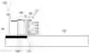
FIG. 1 is a schematic sectional view of the lateral LED backlight module in accordance with an embodiment of the present invention; and
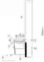
FIG. 2 is a schematic vertical view of the lateral LED in FIG. 1.
DESCRIPTION OF THE PREFERRED EMBODIMENTS
Reference will now be made in detail to the present embodiments of the invention, examples of which are illustrated in the accompanying drawings. Wherever possible, the same reference numbers are used in the drawings and the description to refer to the same or like parts.
Refer to the FIG. 1. FIG. 1 is a schematic sectional view of the lateral LED backlight module in accordance with an embodiment of the present invention. Lateral LED backlight module 100 includes a light emitting diode 110, a heat conductor 120, a circuit board 130, and a base 140.
The light emitting diode 110 includes a substrate 111, a heat sink 112, an LED chip 114, and a plurality of pins 118. The heat sink 112 is fastened to the substrate 111 and connected to the heat conductor 120. The LED chip 114 is disposed on the heat sink 112 and emits light laterally. The pins 118 are mounted on the substrate 111 and extended to the circuit board 130.
The heat sink 112 has an inner surface 112a, a chip-mounting surface 112b, and an outer surface 112c. In accordance with the embodiment of the present invention, the inner surface 112a is connected with a surface of the substrate 111, wherein the substrate comprises metal, non-metal, and polymer. The chip-mounting surface 112b, on the opposing side of the inner surface 112a, provides a chip mounting area to mount an LED chip. The outer surface 112c is connected with a surface of the heat conductor 120 to dissipate the heat derived from the LED chip 114 through the heat sink 112 to the heat conductor 120 of the base 140. The heat sink 112 comprises heat conducting material, such as silver, copper, copper alloys, silver-copper alloys, aluminum, aluminum alloys, ceramic material, and polymers. In an embodiment of the present invention, the heat sink 112 further comprises a reflective coating layer, such as gold or silver coating layer.
In accordance with the embodiment of the present invention, further comprises a reflector 116 disposed on the chip-mounting surface 112b of the heat sink 112 to providing an inner space to define the chip-mounting area and reflecting the light emitted from the LED chip 114. The reflector 116 comprises metal, non-metal or polymer. In an embodiment of the present invention, the reflector 116 further comprises a reflective layer formed on an inner wall of the reflector 116, such as a gold coating layer or a silver coating layer.
The circuit board 130 is disposed on the heat conductor 120 of the base 140.and connected to the substrate 111 of the light emitting diode 110. In an embodiment of the present invention, the heat conductor 120 comprises silver, copper, aluminum and the alloy thereof, the circuit board 130 comprises an insulating material.
A conductive pad 132 is formed on a surface of the circuit board 130 and connected with the pin 118. In an embodiment of the present invention, the pin 118 comprises silver, copper, aluminum, and the alloy thereof. The pin 118 is mounted on the substrate 111 and extended to stick out the substrate 111 to connect with the conductive pad 132. Refer to the FIG. 2. FIG. 2 is a schematic vertical view of the lateral LED backlight module in FIG. 1.
The heat conductor 120 is mounted on the base 140, and the circuit board 130 is mounted on the heat conductor 120. A plurality of conductive pads 132 are set on the circuit board 130 to input the electric power. In accordance with an embodiment of the present invention, the base 140 is formed by a heat conductive metal material, such as silver, copper, aluminum, the alloy thereof, and ceramic material (such as aluminum oxide or aluminum nitride).
A plurality of the light emitting diodes 110 are mounted on the heat conductor 120 and a portion of the base 140 to form a backlight module, wherein the outer surface 112c of the heat sink 112 of each light emitting diode 110 is mounted to a surface of the heat conductor 120.
The engaged substrate 111 and the heat sink substrate 112 can contribute the heat conduction from the light emitting diode 110 to the heat conductor 120, that is, the heat produced from the LED chips 114 are transferred to the heat conductor 120 by the substrate 111 and the heat sink 112, whereby both the heat dissipation area and volume can be enlarged to improve the heat dissipation capability of the lateral LED backlight module 100.
The reflector 116 reflects the light beam emitted form the LED chips 114 to enhance the lighting efficiency, whereby the luminosity of the backlight module can be improved.
Each pin 118 mounted on the substrate 111 of the light emitting diode 110 is extended to stick out the substrate 111 and connected to the respective conductive pad 132 of the circuit board 130 to input electric power.
In summary, the pins of the lateral LED backlight module in accordance with embodiments of the present invention only serve as a conductive electrode, and the heat sink and the heat conductor dissipate the heat derived from the LED chip working, whereby the paths of heat dissipation and electric power conduction are disconnected. Therefore, the balancing point of the heat dissipation and electric power conduct can be controlled to maintain the performance of the lateral LED backlight module.
Although the present invention has been described in considerable detail with reference t certain preferred embodiments thereof, other embodiments are possible. Therefore, the spirit and scope of the appended claims should not be limited to the description of the preferred embodiments contained herein.
It will be apparent to those skilled in the art that various modifications and variations can be made to the structure of the present invention without departing from the scope or spirit of the invention. In view of the foregoing, it is intended that the present invention cover modifications and variations of this invention provided they fall within the scope of the following claims and their equivalents.
Claims
What is claimed is:1. A lateral LED backlight module, comprising:
a base, having a heat conductor;
a circuit board, having a conductive pad formed on a surface thereof, the circuit board disposed on the heat conductor and connected to the substrate; and
at least a light emitting diode, comprising:
a substrate;
a heat sink, fastened to the substrate and connected to the heat conductor;
an LED chip, disposed on the heat sink and emits light laterally; and
a pin, mounted on the substrate and extended to the conductive pad of the circuit board.
2. The lateral LED backlight module of the claim 1, wherein the heat sink comprises an inner surface, a chip-mounting surface, and an outer surface, the inner surface connected to the substrate, the outer surface connected to the heat conductor, and the LED chip mounted to the chip-mounting surface.
3. The lateral LED backlight module of the claim 1, further comprises a reflector disposed on the chip-mounting surface of the heat sink for reflecting the light emitted from the LED chip.
4. The lateral LED backlight module of the claim 3, further comprises a reflective layer formed on an inner wall of the reflector.
5. The lateral LED backlight module of the claim 3, wherein the reflective layer comprises a gold coating layer or a silver coating layer.
6. The lateral LED backlight module of the claim 3, wherein the reflector comprises metal, non-metal or polymer.
7. The lateral LED backlight module of the claim 1, wherein the base comprises a heat conductive material.
8. The lateral LED backlight module of the claim 7, wherein the heat conductive material comprises ceramic material, silver, copper, aluminum and the alloy thereof.
9. The lateral LED backlight module of the claim 8, wherein the ceramic material comprises aluminum oxide or aluminum nitride.
10. The lateral LED backlight module of the claim 1, wherein the heat conductor comprises silver, copper, aluminum and the alloy thereof.
11. The lateral LED backlight module of the claim 1, wherein the circuit board comprises an insulating material.
12. The lateral LED backlight module of the claim 1, wherein the substrate comprises metal, non-metal, and polymer.
13. The lateral LED backlight module of the claim 1, wherein the heat sink comprises silver, copper and the alloy thereof, ceramic material or polymer.
14. The lateral LED backlight module of the claim 1, further comprises a reflective coating layer formed on the heat sink.
15. The lateral LED backlight module of the claim 14, wherein the reflective coating layer comprises gold or silver coating layer.
16. The lateral LED backlight module of the claim 1, wherein the pin comprises silver, copper, aluminum and the alloy thereof.
17. The lateral LED backlight module of the claim 1, wherein the heat produced from the LED chip is transferred to the heat conductor by the substrate and the heat sink.
Images & Drawings included:

Sources:
- United States Patent and Trademark Office - verify current appl. status at the USPTO↗
Recent applications in this class:
- » 20250267784 2025-08-21
HYBRID CONDUCTOR-VAPOR CHAMBER HEAT SINK FOR HIGH POWER THIN ENVELOPE APPLICATIONS - » 20250261300 2025-08-14
METHODS AND APPARATUS TO COOL HOTSPOTS IN INTEGRATED CIRCUIT PACKAGES - » 20250133651 2025-04-24
HEAT DISSIPATION STRUCTURE - » 20250106979 2025-03-27
Embeddable Electrically Insulating Thermal Connector and Circuit Board Including the Same - » 20250056708 2025-02-13
COOLED OPTICS ATTACHED TO A PRINTED CIRCUIT BOARD - » 20240414838 2024-12-12
Printed Circuit Board Arrangement for a Motor Vehicle Headlight - » 20240389217 2024-11-21
OPTICAL MODULE - » 20240373544 2024-11-07
CIRCUIT ASSEMBLY INCLUDING GALLIUM NITRIDE DEVICES - » 20240114614 2024-04-04
Thermal Conduction - Electrical Conduction Isolated Circuit Board with Ceramic Substrate and Power Transistor Embedded - » 20240074032 2024-02-29
OUTLET HEAT SINK FOR COOLING SYSTEM OF A SUPERCOMPUTER ELECTRONIC BOARD
Recent applications for this Assignee:
- » 20090166661 2009-07-02
Light-emitting diode packaging structure and light-emitting diode module - » 20090155937 2009-06-18
Method for packaging LED device - » 20090057701 2009-03-05
Phosphor coating method for fabricating light emitting semiconductor device and applications thereof - » 20090045417 2009-02-19
Light emitting semiconductor device - » 20090026484 2009-01-29
Light emitting diode device - » 20080254393 2008-10-16
Phosphor coating process for light emitting diode - » 20080203422 2008-08-28
Structure of light emitting diode and method to assemble thereof