Water treatment device
US20090173686A1
2009-07-09
12/342,441
2008-12-23
✅ Patent granted
US 8,114,286 B2
2012-02-14
-
-
Ana Fortuna
2029-11-21
Abstract:
Prior water treatment equipments have several water clarifying process filters, water purifier and water reservoir separated from each other, occupying too much space to install under a water tank and resulting inconvenient installment. The water treatment equipments for home cannot be received in water tanks, and thus water clarifier and water purifier are disposed in the water tanks while the water reservoir is disposed separately. Water pipes are connected in between. Therefore, water clarifying processors, water reservoir and water purifier utilizing RO membrane may be integrated to eliminate unnecessary space in existing systems.
Interested in similar patents?
Get notified when new applications in this technology area are published.
Classification:
C02F9/00 IPC
Multistage treatment of water, waste water, or sewage
B01D61/08 » CPC main
Processes of separation using semi-permeable membranes, e.g. dialysis, osmosis or ultrafiltration; Apparatus, accessories or auxiliary operations specially adapted therefor; Reverse osmosis; Hyperfiltration ; Nanofiltration Apparatus therefor
B01D61/10 » CPC further
Processes of separation using semi-permeable membranes, e.g. dialysis, osmosis or ultrafiltration; Apparatus, accessories or auxiliary operations specially adapted therefor; Reverse osmosis; Hyperfiltration ; Nanofiltration Accessories; Auxiliary operations
C02F9/005 » CPC further
Multistage treatment of water, waste water, or sewage Portable or detachable small-scale multistage treatment devices, e.g. point of use or laboratory water purification systems
C02F1/001 » CPC further
Treatment of water, waste water, or sewage Processes for the treatment of water whereby the filtration technique is of importance
C02F1/283 » CPC further
Treatment of water, waste water, or sewage by sorption using coal, charred products, or inorganic mixtures containing them
C02F1/441 » CPC further
Treatment of water, waste water, or sewage by dialysis, osmosis or reverse osmosis by reverse osmosis
C02F1/444 » CPC further
Treatment of water, waste water, or sewage by dialysis, osmosis or reverse osmosis by ultrafiltration or microfiltration
C02F2201/003 » CPC further
Apparatus for treatment of water, waste water or sewage; Construction details of the apparatus Coaxial constructions, e.g. a cartridge located coaxially within another
C02F2209/42 » CPC further
Controlling or monitoring parameters in water treatment Liquid level
C02F2301/024 » CPC further
General aspects of water treatment; Fluid flow conditions Turbulent
C02F2301/026 » CPC further
General aspects of water treatment; Fluid flow conditions Spiral, helicoidal, radial
C02F1/00 IPC
Treatment of water, waste water, or sewage
B01D15/00 IPC
Separating processes involving the treatment of liquids with solid sorbents ; Apparatus therefor
B01D61/00 IPC
Processes of separation using semi-permeable membranes, e.g. dialysis, osmosis, or ultrafiltration; Apparatus specially adapted therefor; Semi-permeable membranes or their production
B01D61/00 IPC
Processes of separation using semi-permeable membranes, e.g. dialysis, osmosis or ultrafiltration; Apparatus, accessories or auxiliary operations specially adapted therefor
Description
TECHNICAL FIELD
The invention relates to a reverse osmosis (RO) water purifying equipment.
BACKGROUND OF THE INVENTION
A reverse osmosis (RO) water purifier (hereafter referred to as a water purifier) used at home performs water clarifying through 3 filters, including a preprocessing filter membrane, an activated carbon filter and a micron filter membrane. Then purified water is produced by the water purifier and stored into a water reservoir disposed independently.
Since these three water clarifying process filters, the water purifier and the water reservoir are separated from each other, this equipment has a deficiency of occupying too much space to install under a water tank.
SUMMARY OF THE INVENTION
Issues to Solve
A preprocessing filter membrane, an activated carbon filter and a micron filter membrane needed for water clarifying are separated in order for filter exchanging;
The water reservoir is disposed separately in a certain corner of kitchen because the water reservoir cannot be received in the water tank. A water pipe is connected in between.
Means for Solving Issues
Water clarifying processors, water reservoir and water purifier utilizing RO membrane for purified water acquisition are integrated to eliminate unnecessary space in existing systems.
EFFECTS OF THE INVENTION
The water treatment equipment of the invention incorporates existing three water clarifying processors, one water reservoir and one water purifier, thereby reducing displacement space and expense.
BRIEF DESCRIPTION OF THE DRAWINGS
FIG. 1 is a schematic view of appearance of a water treatment equipment in accordance with the invention.
FIG. 2 is a schematic view of appearance of a water treatment equipment in accordance with the invention.
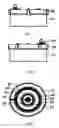
FIG. 3 is a front view of a water treatment equipment in accordance with the invention.
FIG. 4 is a back view of a water treatment equipment in accordance with the invention.
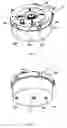
FIG. 5 is a top view of a water treatment equipment in accordance with the invention.
FIG. 6 is a bottom view of a water treatment equipment in accordance with the invention.
FIG. 7 is a right view of a water treatment equipment in accordance with the invention.
FIG. 8 is a left view of a water treatment equipment in accordance with the invention.
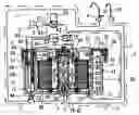
FIG. 9 is a sectional view of FIG. 3 along line A-A.
FIG. 10 is a sectional view of FIG. 5 along line B-B.
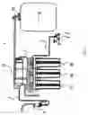
FIG. 11 is an overview of prior art water purifying equipment.
FIG. 12 is an overview of prior art water purifying equipment.
FIG. 13 is a schematic view of appearance of a water treatment equipment in accordance with a second embodiment of the invention.
FIG. 14 is a schematic view of appearance of a water treatment equipment in accordance with a second embodiment of the invention.
FIG. 15 is a front view of a water treatment equipment in accordance with a second embodiment of the invention.
FIG. 16 is a back view of a water treatment equipment in accordance with a second embodiment of the invention.
FIG. 17 is a top view of a water treatment equipment in accordance with a second embodiment of the invention.
FIG. 18 is a bottom view of a water treatment equipment in accordance with a second embodiment of the invention.
FIG. 19 is a right view of a water treatment equipment in accordance with a second embodiment of the invention.
FIG. 20 is a left view of a water treatment equipment in accordance with a second embodiment of the invention.
FIG. 21 is a sectional view of FIG. 15 along line C-C.
FIG. 22 is a sectional view of FIG. 15 along line D-D.
FIG. 23 is a sectional view of FIG. 15 along line E-E.
FIG. 24 is a illustrative figure composed by stacking FIG. 22 and FIG. 23 together.
FIG. 25 is a schematic view of appearance of a water treatment equipment in accordance with a third embodiment of the invention.
FIG. 26 is a schematic view of appearance of a water treatment equipment in accordance with a third embodiment of the invention.
FIG. 27 is a front view of a water treatment equipment in accordance with a third embodiment of the invention.
FIG. 28 is a back view of a water treatment equipment in accordance with a third embodiment of the invention.
FIG. 29 is a top view of a water treatment equipment in accordance with a third embodiment of the invention.
FIG. 30 is a bottom view of a water treatment equipment in accordance with a third embodiment of the invention.
FIG. 31 is a right view of a water treatment equipment in accordance with a third embodiment of the invention.
FIG. 32 is a left view of a water treatment equipment in accordance with a third embodiment of the invention.
FIG. 33 is a sectional view of FIG. 27 along line F-F.
FIG. 34 is a sectional view of FIG. 29 along line G-G.
DESCRIPTION OF SYMBOL
-
- 1 water treatment equipment of the invention
- 2 water supply pipe
- 3 manifold spigot
- 4 purified water outlet spigot
- 5 clarified water outlet spigot
- 6 water intake
- 7 water pipe (ex.: hose)
- 8 purified water outlet
- 9 clarified water outlet
- 10 water clarifier
- 11 filter cartridge
- 12 pressure reservoir (water reservoir)
- 13 water clarifier inlet
- 14 water clarifier outlet
- 15 water purifier
- 16 clarified water intake of water purifier
- 17 water purifier outlet
- 18 membrane-cleaning water outlet
- 19 water discharge outlet
- 20 miscellaneous water outlet
- 21 outlet adjusting knob
- 22 outlet and inlet of pressure reservoir
- 23 ro membrane cartridge of water purifier
- 24 purified water pipe through membrane center
- 25 preprocessing filter membrane
- 26 activated carbon layer
- 27 micron filter membrane
- 28 cartridge base
- 29 cartridge cap
- 30 body cover
- 31 sealing padding
- 32 sealing o-ring
- 33 body
- 34 cylinder of water purifier
- 35 clarified water connecting section
- 36 air space
- 37 sealing padding
- 38 fixed pin
- 39 raw water tank within water clarifier
- 40 water purifier cap
- 41 upper section of water reservoir
- 42 sealing element
- 43 attaching material for filter membrane
- 44 water clarifier barrel
- 45 inner section of water purifier
- 46 manifold pipe
- 47 stopcock in body wall
- 48 water outlet at exit of water clarifier
- 49 clarified water intake
- 50 water clarifier cap (perforated in the middle for water purifier cap)
- 51 water clarifier cap
- 52 water pipeline
- 53 pressure sensor
- 54 electronic computer
- 55 solenoid valve
- 56 floater with built-in magnet
- 57 liquid level switch a
- 58 magnet of floater
- 59 liquid level switch b
- 60 exit of water clarifier
- 61 clarified water intake of water purifier
- 62 battery
- 63 wire
- 64 pipeline opening
- 65 water purifier and clarifier cap
- 66 a pot or bottle for taking purified water
DETAILED DESCRIPTION OF THE INVENTION
A water treatment equipment implemented by the invention has a circular or box shape, in which water introduced by water supply pipe (hereafter referred to as raw water) is firstly clarified and then purified. At the bottom of water reservoir body with purified water outlet and inlet filling and draining purified water, a cylinder of water clarifier and a cylinder of water purifier are provided. The cylinder of water clarifier has an inlet at the intake side of water clarifier, while within the cylinder of water clarifier the cylinder of water purifier has a purified water outlet and a membrane-clarified water outlet. A clarified water processing cartridge is mounted in the cylinder of water clarifier and a water outlet at the exit side of water clarifier is disposed on the top of the cylinder. A water clarifier cap with space for a water purifier cap covers the cylinder of water clarifier with padding interposed so as to form a water clarifier. A reverse osmosis (RO) membrane processing cartridge is mounted in the cylinder of water purifier. A water purifier cap with a clarified water intake receiving clarified water covers the cylinder of water purifier with padding interposed so as to form a water purifier. At the portion of the body excluding said water purifier and said water clarifier, a body cover is fixed and sealed by a fixed pin or other means with padding interposed to form a water reservoir. Raw water is taken from water intake at water purifier inlet side utilizing water pipes such as hose (hereafter referred to as water pipe), then is dispensed from water outlet at exit of water clarifier after clarification, and then is conveyed into the clarified water intake of the water purifier for receiving clarified water through a water pipe for purification in the water purifier. Purified water is dispensed from purified water outlet, and then conveyed into purified water outlet and inlet of water reservoir through a water pipe. The water is stored in the pressure water reservoir with pressure of raw water, and air in the upper section of pressure water reservoir sustains the pressure. When the purified water outlet spigot is opened, purified water is dispensed automatically with the sustained pressure. Membrane-cleaning water, which cleans the surface of RO membrane when producing purified water, is discharged from membrane-cleaning water outlet through a water pipe. Said water clarifier, said water purifier and said pressure water reservoir are formed integrally.
Embodiment 1
The first embodiment of this invention with water clarifier 10, water purifier 15 and pressure water reservoir 12 integrated is described below referring to FIG. 1 to FIG. 10.
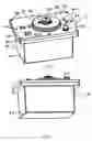
FIG. 1 and FIG. 2 are schematic views of appearance of a water treatment equipment in accordance with the invention. FIG. 3 is a front view. FIG. 4 is a back view. FIG. 5 is a top view. FIG. 6 is a bottom view. FIG. 7 is a right view. FIG. 8 is a left view. FIG. 9 is a sectional view of FIG. 3 along line A-A. FIG. 10 is a sectional view of FIG. 5 along line B-B.
The flowing direction of water when producing purified water is described below with FIG. 10 illustrating the flowing direction of water with arrow referring to connecting water pipe 7.
Reference number 41 of FIG. 10 refers to an upper section of pressure water reservoir 12 (hereafter referred to as water reservoir). Pressure sustaining air section is formed with the function of pressure infused water with purified water produced by raw water pressure. Purified water is dispensed automatically under the sustained pressure with purified water outlet spigot 4.
Fixed pin 38 is a pin connected water reservoir 12 and main body cap 30 fixedly.
Water introduced from water supplying pipe 2 by manifold spigot 3 flows into raw water tank 39 within water clarifier from purified water inlet 13 through water pipe 7. Impurity and solid matter in water is filtered out by a preprocessing filter membrane 25 formed between cartridge base 28 and cartridge cap 29 by means of cross-flow filtering. Then, organic matter is absorbed and filtered by activated carbon layer 26. Solid matter above order of micron is then filtered by micron filter membrane 27. After that, water flows toward clarified water connecting section 35 and is discharged from water clarifier outlet 14.
One part of purified water introduced from clarified water Intake 16 of water purifier by water pipe 7 is filtered into purified water in RO membrane cartridge 23 of water purifier. Purified water is collected into purified water pipe 24 through membrane center and then dispensed from water purifier outlet 17. The other part cleans the surface of RO membrane. Membrane-cleaning water is discharged from membrane-cleaning water outlet 18 through water pipe 7 to miscellaneous water outlet 20.
Purified water dispensed from outlet 17 of water purifier, is either stored into water reservoir marked as 12 through manifold pipe 46 by water pipe 7, or dispensed from purified water outlet spigot 4 through manifold pipe 46 by water pipe 7.
Reference number 41 of FIG. 10 refers to an upper air section to reduce its volume according pressure so as to sustain pressure.
When purified water is produced with RO membrane, purified water is stored in water reservoir 12 and a floater 56 with built-in magnet floats with the level of water reservoir 12. When the level inside water reservoir 12 raises to a certain height, liquid level switch a57 instructs computer 54 to turn off solenoid valve 55 for stopping water supplying as a response through magnet 58 of the floater. Vice versa, liquid level switch A57 instructs computer 54 to turn on solenoid valve 55 for resuming purified water supplying as a response of lowering magnet 58 of the floater with the liquid level.
Reference number 36 of FIG. 10 refers to an upper air section of water clarifier to alleviate impulsion on water clarifier.
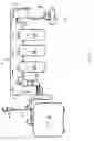
FIG. 11 and FIG. 12 illustrate prior art water purifying devices. Reference number 25 is a preprocessing filter membrane built-in filter, 26 is an activated carbon built-in filter, 27 is a water clarifying filter with micron filter membrane built in, 15 is a water purifier, 12 is a pressure water reservoir. Having a form with the above 5 devices separated, a larger disposing space is required and waste water from water purifier is discharged from the top of water pipe 7.
Embodiment 2
The second embodiment of this invention is described below referring to FIG. 13 to FIG. 24. In the water treatment equipment of this embodiment, water clarifier inlet 13, outlet of water purifier 17 and membrane-cleaning water outlet 18 are respectively connected to individual water pipeline 52 disposed in the wall or at the bottom of pressure water reservoir 12.
FIG. 13 and FIG. 14 are schematic views of appearance of a water treatment equipment in accordance with a second embodiment of the invention. FIG. 15 is a front view. FIG. 16 is a back view. FIG. 17 is a top view. FIG. 18 is a bottom view. FIG. 19 is a right view. FIG. 20 is a left view. FIG. 21 is a sectional view of FIG. 15 along line C-C. FIG. 22 is a sectional view of FIG. 15 along line D-D. FIG. 23 is a sectional view of FIG. 15 along line E-E. FIG. 24 is a illustrative figure composed by stacking FIG. 22 and FIG. 23 together.
The flowing direction of water when producing purified water is illustrated with arrow referring in FIG. 24. This direction is same as that of the first embodiment: water supply pipe 2-manifold spigot 3-solenoid valve 55-water pipe 7-pipeline opening 64 provided on the body cover 30-water pipeline 52-water clarifier Inlet 13-water clarifier outlet 14-clarified water intake 16 of water purifier-purified water pipe 24 through membrane center. Purified water collected into purified water pipe 24 through membrane center either flows to water purifier outlet 17-water pipeline 52-outlet and inlet 22 of pressure reservoir and then stored into water reservoir 12, or flows to water pipeline 52-pipeline opening 64-water pipe 7-purified water outlet spigot 4. While RO membrane-cleaning water flows to membrane-cleaning water outlet 18-water pipeline 52-pipeline opening 64-water pipe 7-miscellaneous water outlet 20.
Embodiment 3
The third embodiment of this invention for integrating the clarifier and the purifier is described below referring to FIG. 25 to FIG. 34. The part of this equipment is omitted in this description.
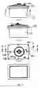
FIG. 25 and FIG. 26 are schematic views of appearance of a water treatment equipment in accordance with a third embodiment of the invention. FIG. 27 is a front view. FIG. 28 is a back view. FIG. 29 is a top view. FIG. 30 is a bottom view. FIG. 31 is a right view. FIG. 32 is a left view. FIG. 33 is a sectional view of FIG. 27 along line F-F. FIG. 34 is a sectional view of FIG. 29 along line G-G.
Water introduced from water supplying pipe 2 by manifold spigot 3 flows into raw water tank 39 from purified water inlet 13 through water pipe 7. Impurity and solid matter in water is filtered out by a preprocessing filter membrane 25 formed between cartridge base 28 and cartridge cap 29 by means of cross-flow filtering. Then, organic matter is absorbed and filtered by activated carbon layer 26. Solid matter above order of micron is then filtered by micron filter membrane 27. After that, water flows toward clarified water connecting section 35 and flows through the inner side of the sealing element 42 separating raw water tank 39 and the above-mentioned clarified water connecting section 35.
One part of purified water introduced from clarified water intake 16 of water purifier by water pipe 7 is filtered into purified water in RO membrane cartridge 23 of water purifier. Purified water is collected into purified water pipe 24 through membrane center and then dispensed from water purifier outlet 17. The other part cleans the surface of RO membrane. Membrane-cleaning water is discharged from membrane-cleaning water outlet 18 through water pipe 7 to miscellaneous water outlet 20.
Purified water dispensed from outlet 17 of water purifier, is dispensed from purified water outlet spigot 4 through water pipe 7, not using water reservoir but taking directly into a pot or bottle.
INDUSTRY APPLICABILITY
Focus on health and environment has been substantially increased. It is desirable for customers to obtain a water treatment equipment of this invention realizing compact disposing space, reduced material and costs.
Claims
What is claimed is:1. A water treatment equipment is an equipment having a circular or box shape in which water introduced by water supply pipe (i.e.: raw water) is firstly clarified and then purified, wherein:
at the bottom of water reservoir body with purified water outlet and inlet filling and draining purified water, a cylinder of water clarifier and a cylinder of water purifier are provided;
the cylinder of water clarifier has an inlet at the intake side of water clarifier, while within the cylinder of water clarifier the cylinder of water purifier has a purified water outlet and a membrane-clarified water outlet;
a clarified water processing cartridge is mounted in the cylinder of water clarifier and a water outlet at the exit side of water clarifier is disposed on the top of the cylinder;
a water clarifier cap with space for a water purifier cap covers the cylinder of water clarifier with padding interposed so as to form a water clarifier;
a reverse osmosis (RO) membrane processing cartridge is mounted in the cylinder of water purifier;
a water purifier cap with a clarified water intake receiving clarified water covers the cylinder of water purifier with padding interposed so as to form a water purifier;
at the portion of the body excluding said water purifier and said water clarifier, a body cover is fixed and sealed by a fixed pin with padding interposed to form a water reservoir;
raw water is taken from water intake at water purifier inlet side utilizing water pipes such as hose, then is dispensed from water outlet at exit of water clarifier after clarification, and then is conveyed into the clarified water intake of the water purifier for receiving clarified water through a water pipe for purification in the water purifier;
purified water is dispensed from purified water outlet, and then conveyed into purified water outlet and inlet of water reservoir through a water pipe;
the water is stored in the pressure water reservoir with pressure of raw water, and air in the upper section of pressure water reservoir sustains the pressure;
when the purified water outlet spigot is opened, purified water is dispensed automatically with the sustained pressure;
membrane-cleaning water, which cleans the surface of RO membrane when producing purified water, is discharged from membrane-cleaning water outlet through a water pipe; and
said water clarifier, said water purifier and said pressure water reservoir are formed integrally.
2. A water treatment equipment of claim 1, wherein water pipelines are provided at the bottom and in the wall of the pressure reservoir connecting clarified water outlet, membrane-cleaning water outlet, purified water outlet of the pressure reservoir, water clarifier inlet, outlets and inlets of said water pipelines are disposed on the body cover of the pressure reservoir, and said pipelines connect said outlets and inlets to the water pipes.
3. A water treatment equipment of claim 1 having a cylinder shape in which water introduced by water supply pipe (i.e.: raw water) is firstly clarified and then purified, wherein:
a cylinder of water clarifier and a cylinder of water purifier are provided;
the cylinder of water clarifier has an inlet for taking in pure water, while within the cylinder of water clarifier the cylinder of water purifier or a component part of the cylinder of water purifier has a purified water outlet and a membrane-clarified water outlet;
a clarified water processing cartridge with a circular central hole is mounted in the cylinder of water clarifier;
a water clarifier and purifier cap covers the cylinder of water clarifier with padding interposed;
a reverse osmosis (RO) membrane processing cartridge is mounted in the cylinder of water purifier or a component part of the cylinder of water purifier;
an end of the cylinder of the water purifier is used as a clarified water intake for taking in clarified water;
raw water is taken from water intake at water purifier inlet side utilizing water pipes such as hose, clarified, then is conveyed into the clarified water intake of the water purifier for receiving clarified water, and then purified in the water purifier;
purified water is dispensed from purified water outlet and inlet;
membrane-cleaning water, which cleans the surface of RO membrane when producing purified water, is discharged from membrane-cleaning water outlet through a water pipe; and
said water clarifier and said water purifier are formed integrally.
Images & Drawings included:


Sources:
- United States Patent and Trademark Office - verify current appl. status at the USPTO↗
Similar patent applications:
- » 20170275189
DEPOSIT MONITORING DEVICE FOR WATER TREATMENT DEVICE, WATER TREATMENT DEVICE, OPERATING METHOD FOR SAME, AND WASHING METHOD FOR WATER TREATMENT DEVICE - » 20200017379
Water treatment device, water treatment system, method of assembling water treatment device, and water treatment method - » 20230373818
A WATER TREATMENT CARTRIDGE FOR A WATER TREATMENT DEVICE, A HEAD OF A WATER TREATMENT DEVICE AND A WATER TREATMENT DEVICE COMPRISING SUCH A CARTRIDGE AND SUCH A HEAD - » 20180036686
WATER QUALITY MONITORING DEVICE, WATER TREATMENT DEVICE, WATER TREATMENT SYSTEM, WATER QUALITY MONITORING METHOD, AND PROGRAM - » 20180002203
WATER TREATMENT DEVICE, WATER TREATMENT METHOD, STERILE WATER PRODUCTION DEVICE, AND STERILE WATER PRODUCTION METHOD - » 20200207652
Cartridge for water treatment for a device for water treatment, a head of a device for water treatment and a device for water treatment comprising such a cartridge and such a head - » 20140190907
Upper-layer cleaning device for water treatment device, and method for cleaning water treatment device filter layer - » 20200199001
A zone cartridge for water treatment for a zone device for water treatment, a head of a zone device for water treatment and a zone device for water treatment comprising such a cartridge and such a head - » 20210214250
OZONE WATER GENERATION DEVICE, WATER TREATMENT DEVICE, OZONE WATER GENERATION METHOD, AND CLEANING METHOD - » 20240383773
MEASUREMENT DEVICE, WATER TREATMENT DEVICE, MEASUREMENT METHOD, AND WATER TREATMENT METHOD
Recent applications in this class:
- » 20250114746 2025-04-10
SYSTEM AND METHOD FOR ELECTRICALLY CONDUCTIVE MEMBRANE SEPARATION - » 20250114745 2025-04-10
FLOW DISTRIBUTOR FOR BATCH OR SEMI-BATCH HYPERFILTRATION SYSTEM - » 20250025833 2025-01-23
INTEGRATED WATERBOARD FOR A WATER PURIFIER - » 20240408546 2024-12-12
SUBMERGED WATER DESALINATION SYSTEM MOTOR COOLED WITH PRODUCT WATER - » 20240342656 2024-10-17
SUSTAINABLE ENERGY-BASED CONTACTLESS REVERSE OSMOSIS (CRO) BY LOW ENERGY PUMP FOR SMART PORTABLE WATER FILTRATION SYSTEM - » 20240198288 2024-06-20
SUSTAINABLE DESALINATION SYSTEMS AND METHODS USING RECYCLED BRINE STREAMS - » 20240181393 2024-06-06
Cartridge filter - » 20240181392 2024-06-06
IMPROVED REVERSE OSMOSIS OR NANOFILTRATION PROCESS FOR CLEANING WATER - » 20240165562 2024-05-23
REVERSE OSMOSIS OR NANOFILTRATION PROCESS FOR CLEANING WATER - » 20240123404 2024-04-18
SYSTEM AND METHOD FOR DESALINATION OF WATER