Method and device for piloting an aircraft optimizing the control of the ailerons in an enhanced-lift configuration
US20090230253A1
2009-09-17
12/294,588
2007-05-21
✅ Patent granted
US 8,083,178 B2
2011-12-27
WO; PCT/FR2007/000851; 20070521
WO; WO2007/138179; 20071206
Galen Barefoot
2029-03-17
Abstract:
In conformance with the invention, based on the incident conditions and velocity, the steering of the ailerons is weakly negative (b0) or corresponds either to the maximum sharpness of the aircraft (b1), or the optimal lift of the latter (b2).
Inventors:
- Frédéric Sauvinet 10 🇫🇷 Tournefeuille, France
- Sophie LAMBEAUX 3 🇫🇷 TOURNEFEUILLE, France
- Franck Delaplace 10 🇫🇷 Toulouse, France
Assignee:
- AIRBUS OPERATIONS (S.A.S.) 2,221 🇫🇷 Toulouse, France
- AIRBUS FRANCE 623 🇫🇷 Toulouse, France
Interested in similar patents?
Get notified when new applications in this technology area are published.
Classification:
B64C9/06 » CPC main
Adjustable control surfaces or members, e.g. rudders with two or more independent movements
G05D1/0808 » CPC further
Control of position, course or altitude of land, water, air, or space vehicles, e.g. automatic pilot; Control of attitude, i.e. control of roll, pitch, or yaw specially adapted for aircraft
B64C9/00 IPC
Adjustable control surfaces or members, e.g. rudders
G05D1/08 IPC
Control of position, course or altitude of land, water, air, or space vehicles, e.g. automatic pilot Control of attitude, i.e. control of roll, pitch, or yaw
B64C13/16 » CPC further
Control systems or transmitting systems for actuating flying-control surfaces, lift-increasing flaps, air brakes, or spoilers; Initiating means actuated automatically, e.g. responsive to gust detectors
B64C5/08 IPC
Stabilising surfaces mounted on or supported by wings
Description
The present invention relates to a piloting method and device for aircraft making it possible to optimize the control of the ailerons in an enhanced-lift configuration.
It is known that, among other movable aerodynamic surfaces, the two symmetric wings of an aircraft can comprise leading edge slats and/or trailing edge flaps able when they are deployed to generate the enhanced lift of said wings, and also ailerons to control said aircraft in terms of roll. In an enhanced-lift configuration such as this, the ailerons are customarily deflected downwards so as to take a compensated neutral position, participating in the overall lift-enhancement of the aircraft.
However, from a compensated neutral position such as this, the roll effectiveness of said ailerons is relatively low, so that the roll performance of the aircraft is heavily degraded. Moreover, as a result of this low roll effectiveness, the aircraft exhibits a reduced margin with respect to the phenomenon of pilot-induced oscillation.
The object of the present invention is to remedy these drawbacks.
To this end, according to the invention, the method of piloting an aircraft comprising two symmetric wings provided:
-
- with movable lift-enhancing aerodynamic surfaces, able to afford said wings either a smooth configuration, or at least one enhanced-lift configuration; and
- with roll control ailerons, whose neutral position corresponds to a zero deflection, when said wings exhibit said smooth configuration,
is noteworthy in that, in the enhanced-lift configuration of said wings, said ailerons are afforded, in an identical manner on the two wings and disregarding a possible roll control order: - when the incidence and the speed of the aircraft are respectively less than an incidence threshold and greater than a speed threshold, a first state corresponding to a position deflected upwards by an angle, for example at the most equal to 5°, such that said ailerons preserve their roll effectiveness almost intact; and
- when the incidence of the aircraft is equal to or greater than said incidence threshold or when the speed of the aircraft is equal to or less than said speed threshold, a second state corresponding:
- either to a first downward deflection of value corresponding at least approximately to the maximum finesse of the aircraft, if the latter is in the takeoff or re-takeoff phase,
- or to a second downward deflection of value corresponding at least approximately to the optimal lift of the aircraft, if the latter is in the landing phase.
Thus, by virtue of the present invention, when the aircraft is in an enhanced-lift configuration, three deflected positions rather than just one are now communicated to said ailerons:
-
- when the aircraft is in the landing approach or at the end of takeoff, the upward deflection of the ailerons is sufficiently small for said ailerons to exhibit excellent roll effectiveness. Moreover, in this position, the ailerons not only generate little noise, but also combat the wake vortices by generating a local vortex which, associated with the other vortices generated by the airplane, favors the progressive dissipation of said wake vortices;
- when the aircraft lands, the deflection of the ailerons corresponds to the maximum lift, that is to say to the lowest stall speed, and therefore to the lowest landing speed, this constituting optimal landing conditions. Moreover, in the landing phase, the deflection of the ailerons generates a maximum drag, thereby favoring the deceleration of the aircraft; and
- when the aircraft begins a takeoff, the deflection of the ailerons affords it good lift and not too high a drag (the finesse corresponding to the ratio of the lift to the drag), thus helping the aircraft to take off.
Preferably, in order to add dynamism to the switch from one state to another, it is advantageous, on the one hand, to determine the position of the incidence a with respect to said incidence threshold as by comparing the expression α+K1·q with said threshold αs, K1 being a positive constant coefficient and q being the pitch rate of said aircraft (that is to say the derivative with respect to time of said incidence a), and, on the other hand, to determine the position of the speed Vc of the aircraft with respect to said speed threshold Vs by comparing the expression Vc+K2·dVc/dt with said threshold Vs, K2 being a positive constant coefficient and dVc/dt the acceleration of said airplane.
The value of said incidence and speed thresholds depends on the lift-enhancing position of said lift-enhancing aerodynamic surfaces and the Mach number.
The switching of the ailerons from one state to another can be reversible or irreversible. For example, after being switched from said first state to the second, said ailerons remain in said second state even if the incidence and speed conditions again become in accordance with said first state. On the other hand, after being switched from said first state to the second, said ailerons can switch back, preferably with hysteresis, to said first state when the incidence and speed conditions again become in accordance with said first state.
For the implementation of the method in accordance with the present invention, it is possible to use a device mounted aboard said aircraft and comprising:
-
- first comparison means for comparing said incidence a with said incidence threshold αs;
- second comparison means for comparing said speed Vc with said speed threshold Vs;
- logic means of OR type receiving the results of the comparisons performed by said first and second comparison means;
- first switching means for choosing between said first deflection and said second deflection; and
- second switching means, actuated by said logic means for choosing between the result of the choice of said first switching means and said position deflected upwards by an angle such that said ailerons preserve their roll effectiveness almost intact.
The figures of the appended drawing will elucidate the manner in which the invention can be carried out. In these figures, identical references designate similar elements.
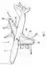
FIG. 1 shows in schematic perspective a wide-bodied civil airplane provided with slats and lift-enhancing flaps, and also with ailerons.
FIGS. 2, 3 and 4 are charts illustrating respectively the roll effectiveness, the finesse and the lift of the airplane of FIG. 1 as a function of the angle of deflection of the ailerons.
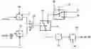
FIG. 5 is the schematic diagram of a device for implementing the method in accordance with the present invention.
The civil transport airplane 1, schematically represented in perspective in FIG. 1, comprises two wings 2G and 2D in all respects symmetric with one another with respect to the fuselage 3.
The wings 2G and 2D respectively comprise leading edge slats 4G, 4D, trailing edge flaps 5G, 5D (said slats and flaps constituting lift-enhancing aerodynamic surfaces for the airplane 1) and roll control ailerons 6G, 6D.
In a customary manner, the slats and the flaps 4G, 4D; 5G, 5D are deployable and retractable so as to communicate to the wings 2G, 2D, and therefore to the airplane 1, a smooth configuration when they are retracted and at least one enhanced-lift configuration when they are deployed.
Likewise, the ailerons 6G, 6D are articulated in rotation on said wings 2G, 2D so as to be able to take various deflection positions with respect to the latter.
Represented in FIG. 2 is a known chart illustrating the roll effectiveness R of the ailerons 6G, 6D on the airplane 1 as a function of the angle of deflection b of said ailerons. On this chart, positive angles b correspond to a downward deflection and negative angles b to an upward deflection. From this known chart, it is readily noted that the roll effectiveness R of said ailerons is good so long as the angle of deflection b takes a value close to zero. Thus, for a negative value b0 close to zero, for example at most equal to −5°, the roll effectiveness of the ailerons is practically as good as when the angle of deflection is zero.
Moreover, represented in FIG. 3 is another known chart illustrating the finesse F of the airplane 1, that is to say the ratio of its lift to its drag, as a function of said angle of deflection b of the ailerons 6G, 6D. It may be seen there that said finesse passes through a maximum Fmax for a positive value b1 of said angle of deflection b.
Finally, represented in FIG. 4 is a third known chart illustrating the lift P of the airplane 1 as a function of its incidence α, for the negative value b0 and the positive values b1 and b2 (with b2>b1) of the angle of deflection b of the ailerons 6G, 6D. The latter chart illustrates that, for a determined value ad of α, the corresponding value P0, P1 or P2 of the lift P is all the larger the larger the value of the angle of deflection b.
The present invention is described hereinafter with regard to the schematic diagram of FIG. 5, supported by the characteristics illustrated by FIGS. 2, 3 and 4.
The device intended to implement the method according to the invention and represented by the schematic diagram of FIG. 5 comprises:
-
- a first comparator 11 receiving, on one of its inputs, the sum of the current incidence a of the airplane 1 and of a term K1·q, consisting of the product of a positive constant K1 and of the current pitch rate q of said airplane and, on its other input, an incidence threshold αs, whose value is dependent on the position of the slats 4G, 4D, the flaps 5G, SD and the Mach number, said first comparator 11 delivering a signal only when the expression α+K1·q is equal to or greater than αs;
- a second comparator 12 receiving, on one of its inputs, the sum of the current speed Vc of the airplane 1 and of a term K2·dVc/dt, consisting of the product of a positive constant K2 and of the derivative dVc/dt of the speed of said airplane and, on its other input, a speed threshold Vs, whose value is dependent on the position of the slats 4G, 4D, the flaps 5G, SD and the Mach number, said second comparator 12 delivering a signal only when the expression Vc+K2·dVc/dt is equal to or less than Vs;
- a logic gate 13, of OR type, whose inputs are respectively linked to the outputs of the comparators 11 and 12;
- a first switch 14 receiving respectively at its inputs the two positive values b1 and b2 of the angle of deflection b, corresponding respectively to the maximum finesse Fmax and to the optimal lift P2 for the aircraft 1, said switch 14 addressing one or the other of these values b1 or b2 to its output in response to an order 15 corresponding respectively to the fact that the airplane 1 is in the takeoff phase (or re-takeoff phase) or in the landing phase;
- a second switch 16 receiving respectively on its two inputs the negative value b0 and one or the other of the positive values b1 or b2 (as a function of the command 15 of the first switch 14), said second switch 16 being commanded by the output of the logic gate 13 to address either the negative value b0, or one or the other of the positive values b1, b2 to a filter 17; and
- an adder 18 making it possible to add to a piloting order db for the ailerons 6G, 6D, one or the other of the values b0, b1 or b2.
In the light of the schematic diagram of FIG. 1, it is readily understood that, in the enhanced-lift configuration of the wings 2G, 2D:
-
- when the expression α+K1·q is less than the incidence threshold as and the expression Vc+K2·dVc/dt is greater than the speed threshold Vs, the logic gate 13 does not deliver any signal, so that the negative deflection b0 is imposed in common on the ailerons 6G, 6D, through the filter 17 and after possible addition of a roll control order db. From what is shown by the chart of FIG. 2, and from the associated comments, it will be understood that the low negative deflection b0 allows possible effective roll control; and
- when the expression α+K1·q is equal to or greater than the incidence threshold as or the expression Vc+K2·dVc/dt is equal to or less than the speed threshold Vs, the logic gate 13 toggles the second switch 16, so that the positive deflection b1 corresponding to takeoff or the positive deflection b2 corresponding to landing (as a function of the state of the first switch 15) is imposed in common on the ailerons 6G, 6D, through the filter 17 and after possible addition of a roll control order db. The deflections b1 and b2 can be respectively of the order of 5° and 10°.
Represented by dashed lines 7 and 8 respectively in FIG. 4 is the switchover from the deflection b0, on the one hand, to the deflection b1 or b2, on the other hand, when said second switch 16 toggles.
It will be noted that, by virtue of the action of the filter 17, the switchover from the deflection b0 to the deflection b1 or b2 occurs gently, with no jerkiness.
The second switch 16 can be monostable and return spontaneously to its initial position corresponding to the deflection b0, as soon as the logic gate 13 no longer addresses any signal to it. As a variant, the second switch 16 can be bistable and remain in its toggled position corresponding to the deflection b1 or b2, even if the logic gate 13 no longer addresses any signal to it.
Claims
1-9. (canceled)
10. A method for piloting an aircraft (1) comprising two symmetric wings (2G, 2D) provided:
with movable lift-enhancing aerodynamic surfaces (4G, 4D; 5G, SD), able to afford said wings either a smooth configuration, or at least one enhanced-lift configuration; and
with roll control ailerons (6G, 6D), whose neutral position corresponds to a zero deflection, when said wings exhibit said smooth configuration,
wherein, in the enhanced-lift configuration of said wings, said ailerons (6G, 6D) are afforded, in an identical manner on the two wings and disregarding a possible roll control order (db):
when the incidence and the speed of the aircraft are respectively less than an incidence threshold (αs) and greater than a speed threshold (Vs), a first state (b0) corresponding to a position deflected upwards by an angle such that said ailerons (6G, 6D) preserve their roll effectiveness almost intact; and
when the incidence of the aircraft is equal to or greater than said incidence threshold (αs) or when the speed of the aircraft is equal to or less than said speed threshold (Vs), a second state corresponding:
either to a first downward deflection (b1) of value corresponding at least approximately to the maximum finesse (Fmax) of the aircraft, if the latter is in the takeoff or re-takeoff phase,
or to a second downward deflection (b2) of value corresponding at least approximately to the optimal lift (P2) of the aircraft, if the latter is in the landing phase.
11. The method as claimed in claim 10, wherein the position of the incidence a with respect to said incidence threshold as is determined by comparing the expression α+K1·q with said threshold αs, K1 being a positive constant coefficient and q being the pitch rate of said aircraft.
12. The method as claimed in claim 11, wherein said incidence threshold as depends on the position of said lift-enhancing aerodynamic surfaces and the Mach number.
13. The method as claimed in claim 10, wherein the position of the speed Vc of the aircraft with respect to said speed threshold Vs is determined by comparing the expression Vc+K2·dVc/dt with said threshold Vs, K2 being a positive constant coefficient and dVc/dt the acceleration of said airplane.
14. The method as claimed in claim 13, wherein said speed threshold (Vs) depends on the position of said lift-enhancing aerodynamic surfaces and the Mach number.
15. The method as claimed in claim 10, wherein, after being switched from said first state to the second, said ailerons remain in said second state even if the incidence and speed conditions again become in accordance with said first state.
16. The method as claimed in claim 10, wherein, after being switched from said first state to the second, said ailerons switch back to said first state when the incidence and speed conditions again become in accordance with said first state.
17. A device for implementing the method as claimed in claim 10, wherein it comprises:
first comparison means (11) for comparing said incidence α with said incidence threshold αs;
second comparison means (12) for comparing said speed Vc with said speed threshold Vs;
logic means (13) of OR type receiving the results of the comparisons performed by said first and second comparison means (11, 12);
first switching means (14) for choosing between said first deflection and said second deflection; and
second switching means (16), actuated by said logic means (13), for choosing between the result of the choice of said first switching means (14) and said position deflected upwards by an angle such that said ailerons (6G, 6D) preserve their roll effectiveness almost intact.
18. An aircraft implementing the method specified under claim 10.
Images & Drawings included:


Sources:
- United States Patent and Trademark Office - verify current appl. status at the USPTO↗
Recent applications in this class:
- » 20230365249 2023-11-16
Compact aircraft control surface track mechanism - » 20200047872 2020-02-13
Tailless aircraft - » 20190359313 2019-11-28
Flight control surface assembly - » 20190256191 2019-08-22
Aircraft, controller and control method of aircraft, and recording medium storing computer software program for controlling aircraft - » 20190127044 2019-05-02
Mechanical droop for spoiler operation - » 20120145834 2012-06-14
Aircraft attitude control configuration - » 20090283632 2009-11-19
Aircraft attitude control configuration - » 20070102575 2007-05-10
Aircraft attitude control configuration
Recent applications for this Assignee:
- » 20250201879 2025-06-19
Soft-Start Strategy Of A Fuel Cell - » 20250196988 2025-06-19
DEVICE FOR ABSORBING ENERGY BY COMPRESSION, AIRCRAFT COMPRISING AT LEAST ONE SUCH DEVICE - » 20250136265 2025-05-01
AIRCRAFT CARGO DOOR ACTUATION SYSTEM - » 20250136264 2025-05-01
AIRCRAFT CARGO DOOR ACTUATION SYSTEM - » 20250115365 2025-04-10
AIRCRAFT COMPRISING AT LEAST ONE ENGINE ATTACHMENT SYSTEM THAT HAS REDUCED VERTICAL BULK - » 20250078670 2025-03-06
METHOD FOR MANAGING TAXIING PATHS - » 20250076893 2025-03-06
METHOD AND DEVICE FOR OPTIMIZING A CLIMB PHASE OF AN AIRCRAFT, IN PARTICULAR IN TERMS OF FUEL CONSUMPTION - » 20250074608 2025-03-06
AIRCRAFT PYLON FAIRING, FAIRING ASSEMBLY, AIRCRAFT PYLON AND AIRCRAFT - » 20250074574 2025-03-06
AIRCRAFT FUSELAGE - » 20250042565 2025-02-06
AIRCRAFT AIR INTAKE COMPRISING AN OUTER WALL AND FRONT AND REAR FRAMES LINKED BY AT LEAST ONE JOINING ELEMENT DISTINCT FROM THE OUTER WALL