Snow ski-bike
US20090230641A1
2009-09-17
11/906,336
2008-03-14
Abstract:
The Snow Ski-Bike comprises a main frame similar to the ones used on today's downhill type mountain bikes. It features a suspension system and ski pivot assembly removably connected to the main frame. The main frame does not incorporate a drive system or form of self propulsion as it is primarily designed to be carried to the top of the mountain by ski lift. The ski pivot assemblies are each equipped with horizontal return pivot shocks, hydraulically controlled brakes, and dual retractable traction fins for each ski. These components will serve as an integral part which will support The Snow Ski-Bike main frame on the snow covered ground. This provides a versatile arrangement that suitably combines stability, agility, and the ability to reach high speeds on various types of snow or ice covered terrains.
Interested in similar patents?
Get notified when new applications in this technology area are published.
Classification:
B62B13/04 » CPC main
Sledges with runners characterised by arrangement of runners arranged in a single line
B62B13/16 » CPC further
Sledges with runners Collapsible or foldable sledges
A63C5/00 IPC
Skis or snowboards; Accessories therefor encompasses groups – only.
A63C5/00 IPC
Skis or snowboards
Description
BRIEF DESCRIPTION OF DRAWINGS
A preferred embodiment of the present invention will now be described with reference to the accompanying drawings in which:
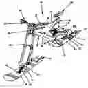
FIG. 1 is a perspective view of The Snow Ski-Bike constructed in accordance with the present invention. It should be noted at this time, that the front fork suspension is interchangeable with any of the current manufacturer's designs already in use. In this perspective view, all components and mounting hardware are connected giving the observer a seemingly mental picture of how all the parts function together.
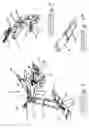
FIG. 2 is a perspective view of the typical ski bottom equipped with dual traction fins. The braking system cannot be seen in this drawing, but is featured in the previous figure. The front and rear brakes are positioned on the top-side rear-most section of the ski.
FIG. 3 is a segmented view showing the embodiment of the construction of both the swing arm and rear shock assembly and its connection to the ski pivot shock assembly which eventually mounts to the rear ski.
IDENTIFICATION OF THE COMPONENTS
10 Snow Ski-Bike
12 Main Frame
13 Top Tube
14 Down Tube
16 Seat Tube
18 Alternate Seat Tube
20 Seat
21 Bottom Brackett
22 Foot Holders
24 Foam Rubber Safety Pad
30 Front Head Tube
32 Front Suspension Fork
34 Handle Bars
36 Brake Levers and Cables
38 Swing Arms
40 Sealed Bearing Pivot Point
42 Rear Suspension Shock
44 Shock Connectors
46 Ski Pivot Assembly
48 Fastener Bolts
50 Horizontal Leveler Shock
52 Shock Mount
54 Shock Retainer Bolt
56 Ski
58 Traction Fins
60 Brake Assembly
DESCRIPTION
FIG. 1 shows The Snow Ski-Bike (10), according to the possible embodiment of the present invention. The Snow Ski-Bike (10) comprises a mainframe (12), which may be as illustrated, substantially similar to a conventional bicycle frame. The mainframe (12), has a down tube (14), a top tube (13), a seat tube (16), for supporting a seat (20), a front head tube (30), a bottom bracket (21), with foot holders (22), and foam rubber safety pad (24). Mounted on the top tube (13), the seat (20), has an alternate seat tube (18), and is adjustable which will add virtual length to the top tube (13).
The Snow Ski-Bike (10) is called as such because it is primarily designed for the winter season. It should be noted at this time that this particular embodiment of The Snow Ski-Bike does not contain a form of propulsion as it is designed to be carried to the top of the mountain by the ski lift.
The front of the main frame (12) is supported by a steer able assembly that is operatively connected to the head tube (30). This assembly is actuated by the user through the handle bars (34). It consists of a front suspension fork (32), and detachable ski pivot assembly (46), with ski (56). The ski (56), will return to the true horizontal position when hitting an obstacle on the terrain at the moment the horizontal leveler shock (50), is engaged and cycles through its rebound phase.
FIG. 2 The ski assemblies (46 & 56), are removable/connected to both the front and rear suspensions of the main frame (12), easing the storage or the transportation or The Snow Ski-Bike (10).
Each of the ski assemblies as shown in FIGS. 1 and 2 comprises a set of traction fins and a brake assembly.
FIG. 3 The rear suspension shock assembly (42), comprises of a pivoted double swing arm (38), which is operatively connected to the main frame (12). The shock is mounted between the swing arm assembly (38), and the rear most portion of the main frame (12).
A ski (56), and ski pivot assembly (46), which is nearly identical to assembly used in conjunction with the front suspension are also removable/connected for ease of storage and transportation.
Although a preferred embodiment of The Snow Ski-Bike, has been described in basic detail herein and illustrated in the accompanying drawings, it should be understood that The Snow Ski-Bike, is not limited to this precise embodiment and that various changes and modifications may be effected therein without departing from the scope or spirit of the present invention.
Claims
What is claimed is:1. A Snow Ski-Bike comprising;
a mainframe having a front head tube, top tube, down tube, and a rear pivoted swing arm comprising a left and a right tube;
a front steerable supporting assembly operatively connected to the head tube to support the front of the frame when the bike is on the ground;
a front ski which is removable and connected to the front steerable supporting assembly comprising a brake for speed control, and duel traction fins to control drift;
a rear ski which is removable and connected to the rear pivoted swing arm comprising a brake and duel traction fins which are identical to those of the front ski, while supporting the rear of the frame when the bike is on the ground;
a horizontal leveler shock attached to the ski pivot assembly;
an in line double seat tube as an integral part of the mainframe for two position adjustability.
Images & Drawings included:
Sources:
- United States Patent and Trademark Office - verify current appl. status at the USPTO↗
Recent applications in this class:
- » 20100109267 2010-05-06
SKI BIKE - » 20090108548 2009-04-30
Monoski - » 20090033047 2009-02-05
Skiing implement having a simplified structure - » 20070267827 2007-11-22
Snow-sliding vehicle - » 20070024028 2007-02-01
Monoski - » 20060108750 2006-05-25
Snap-on ski attachment with brake for kick scooter - » 20050258609 2005-11-24
Snow scooter