ELECTRIC SENSOR DECORATIVE MECHANISM
US20090239442A1
2009-09-24
12/053,631
2008-03-24
Abstract:
A provide electric sensor decorative mechanism is disclosed. The mechanism comprises an ornamental article, a base seat mounted to the ornamental article. The base seat contains a coil to emit a high frequency electrical wave, and when the coil within the ornamental article receives the high frequency wave, a voltage is produced to drive a motor mounted to the ornamental article, hence the ornamental article rotates with different modes.
Interested in similar patents?
Get notified when new applications in this technology area are published.
Classification:
G09F19/08 » CPC main
Advertising or display means not otherwise provided for incorporating moving display members Dolls, faces, or other representations of living forms with moving parts
A63H3/28 IPC
Dolls Arrangements of sound-producing means in dolls; Means in dolls for producing sounds
Description
BACKGROUND OF THE INVENTION
(a) Technical Field of the Invention
The present invention relates to an ornamental article enclosed in a sealed space and in particular, an enclosed ornamental article which is triggered to rotate via electrical signal.
(b) Description of the Prior Art
Conventional music box contains a rotating mechanism to drive a music device within the box. Generally, the device has a coiled spring and the spring is rotated clockwise. When the tightening of the spring is released, the mechanical energy generated by the spring will drive a ornamental object to rotate and to produce a music simultaneously. In the conventional music box, the driving mechanism, i.e., the spring and the ornamental object of the conventional music box are not sealed, the parts are very often dismantled and damaged after a period of time. These structure cannot be employed on rotating ornamental object where a sealed environment is required. If batteries are used to provide power to the ornamental object, the batteries are required to be replaced after some time, and requirement of a sealed mechanism is reduced when the power of the batteries reduces. In view of the drawbacks, it is an object of the present invention to provide an ornamental article enclosed in a sealed space.
SUMMARY OF THE INVENTION
The primary purpose of the present invention is to provide an electric sensor decorative mechanism comprising an ornamental article and a base seat mounted to the ornamental article characterized in that the ornamental article has a sealed space containing the ornamental article and the center slot body at the bottom section of the sealed space is provided with coil connected to a micro motor which rotates to drive a gear module so as to drive the gears at the bottom of the ornamental article, thereby the ornamental article rotates with different modes, the base seat provides a holding for the ornamental article or a contact to trigger electric-sensing transmission, and the base seat makes use of direct current or alternate current to generate a high frequency wave, the coil mounted below the base seat emits electrical wave, thereby when the coil receives the high frequency wave, a direct voltage is obtained to drive the motor mounted to drive the ornamental article so that the ornamental article rotates.
Yet still a further object of the present invention to provide electric sensor decorative mechanism, wherein the ornamental article within the sealed space is connected to a magnet or a diode.
Yet a further object of the present invention is to provide electric sensor decorative mechanism, wherein the ornamental article within the sealed space drive by re-chargeable batteries and the base seat is used as a charger.
The foregoing object and summary provide only a brief introduction to the present invention. To fully appreciate these and other objects of the present invention as well as the invention itself, all of which will become apparent to those skilled in the art, the following detailed description of the invention and the claims should be read in conjunction with the accompanying drawings. Throughout the specification and drawings identical reference numerals refer to identical or similar parts.
Many other advantages and features of the present invention will become manifest to those versed in the art upon making reference to the detailed description and the accompanying sheets of drawings in which a preferred structural embodiment incorporating the principles of the present invention is shown by way of illustrative example.
BRIEF DESCRIPTION OF THE DRAWINGS
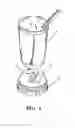
FIG. 1 is a perspective view of the preferred embodiment of the present invention.
FIG. 2 is a schematic view showing a separation between the ornamental article (cup) and the base seat of the present invention.
FIG. 3 is a schematic view showing the base of the sealed space of the present invention.
FIG. 4 is a schematic view showing sectional view of the ornamental article.
FIG. 5 is a schematic view of another preferred embodiment in accordance with the present invention.
FIG. 6 is a schematic view showing the circuit at the base seat of the present invention.
FIG. 7 is a schematic view showing the circuit of the ornamental article within the sealed space.
DETAILED DESCRIPTION OF THE PREFERRED EMBODIMENTS
The following descriptions are of exemplary embodiments only, and are not intended to limit the scope, applicability or configuration of the invention in any way. Rather, the following description provides a convenient illustration for implementing exemplary embodiments of the invention. Various changes to the described embodiments may be made in the function and arrangement of the elements described without departing from the scope of the invention as set forth in the appended claims.
Referring to FIGS. 1 and 2, there is shown a preferred embodiment of an ornamental design enclosed in a sealed space. In this preferred embodiment, a cup is used as the ornamental design.
The ornamental design comprises a cup 1 and a base seat 2. The bottom section of the body of the cup 1 is a sealed space 11, and within the sealed space 11, an ornamental article 12 is contained.
The cup 1 is mounted onto the base seat 2, and the ornamental article 12 enclosed within the sealed space is provided with kinetic energy. The power source of the base seat 2 is from the batteries or externally connected to electrical supplies for home appliances, and the ornamental article 12 is triggered to move by electrical current.
As shown in FIGS. 3 and 4, the bottom section of the structure of the sealed space 11 is depicted in FIG. 3. The center slot 111 of the bottom section is provided with coil 112 which is connected to a charger micro motor 113. The power of rotation of the motor 113 drives a gear module 114, which in turn drives the gear 121 mounted below the ornamental article 12. Thus, the ornamental article 12 is rotated in various of modes.
FIG. 5 shows the ornamental article 12 within a sealed space being provided a reciprocating movement. Similarly, the electrical sensing from the base seat causes the swinging rod component 122 to reciprocate via the magnet mounted to the swinging rod components, the generation of magnetic field at the bottom seat 2 causes the reciprocation movement.
Referring to FIGS. 6 and 7, there is shown the circuit diagrams of the sealed ornamental article 12 and that at the base seat. The circuit at the base seat 2 generates a high frequency wave from the supplied direct current or from the current for home appliance. The coils L1, L2 at the base seat emit externally a high frequency wave. When the coil L3 at the interior of the ornamental article 12 receives the high frequency wave, a direct current voltage is received. This voltage will drive the motor, magnet, diode of the ornamental article, or uses as battery charger to drive the ornamental article.
It will be understood that each of the elements described above, or two or more together may also find a useful application in other types of methods differing from the type described above.
While certain novel features of this invention have been shown and described and are pointed out in the annexed claim, it is not intended to be limited to the details above, since it will be understood that various omissions, modifications, substitutions and changes in the forms and details of the device illustrated and in its operation can be made by those skilled in the art without departing in any way from the spirit of the present invention.
Claims
I claim:1. An electric sensor decorative mechanism comprising an ornamental article and a base seat mounted to the ornamental article characterized in that the ornamental article has a sealed space containing the ornamental article and the center slot body at the bottom section of the sealed space is provided with coil connected to a micro motor which rotates to drive a gear module so as to drive the gears at the bottom of the ornamental article, thereby the ornamental article rotates with different modes,
the base seat provides a holding for the ornamental article or a contact to trigger electric-sensing transmission, and the base seat makes use of direct current or alternate current to generate a high frequency wave, the coil mounted below the base seat emits electrical wave, thereby when the coil receives the high frequency wave, a direct voltage is obtained to drive the motor mounted to drive the ornamental article so that the ornamental article rotates.
2. The electronic sensor decorative mechanism of claim 1, wherein the ornamental article within the sealed space is connected to a magnet or a diode.
3. The electronic sensor decorative mechanism of claim 1, wherein the ornamental article within the sealed space drive by re-chargeable batteries and the base seat is used as a charger.
Images & Drawings included:


Sources:
- United States Patent and Trademark Office - verify current appl. status at the USPTO↗
Recent applications in this class:
- » 20240371303 2024-11-07
Inflatable ornament - » 20220375372 2022-11-24
COMPONENT OF KINETIC SCULPTURE - » 20220319363 2022-10-06
Kinetic sculpture system - » 20200184860 2020-06-11
Advertising device called the sign spinner - » 20190318673 2019-10-17
INFLATABLE DECORATION AND BASE - » 20180174499 2018-06-21
Inflatable display assembly for detachable external air blower - » 20170162088 2017-06-08
Figure, base, and figure system - » 20150206465 2015-07-23
FLEXIBLE EXPRESSION DISPLAY DEVICE - » 20150135569 2015-05-21
FLASHING AIR DANCER - » 20130064599 2013-03-14
Magnetically coupled mannequin joint