Impact pads and a process for manufactring the same
US20090280288A1
2009-11-12
11/919,174
2006-06-13
✅ Patent granted
US 8,337,971 B2
2012-12-25
WO; PCT/IN2006/000197; 20060613
WO; WO2007/054959; 20070518
Alexander Thomas
2028-03-09
Abstract:
An impact pad comprising an upper part, a middle part, and a lower part, the said upper part being configured as a single piece with a plurality of protrusions on a under side there of facing the middle part, such that said protrusions are adapted to fit in the grooves provided on the top surface of the middle part, the bottom surface of the middle part being provided with the third part, namely means for fastening impact pads on the main support frame with clamps.
Assignee:
- TEGA INDUSTRIES LIMITED 17 🇮🇳 KOLKATA, India
Interested in similar patents?
Get notified when new applications in this technology area are published.
Classification:
E01F15/0453 » CPC main
Safety arrangements for slowing, redirecting or stopping errant vehicles, e.g. guard posts or bollards; Arrangements for reducing damage to roadside structures due to vehicular impact; Continuous barriers extending along roads or between traffic lanes essentially made of longitudinal beams or rigid strips supported above ground at spaced points Rails of materials other than metal or concrete, e.g. wood, plastics; Rails of different materials, e.g. rubber-faced metal profiles, concrete-filled steel tubes
B65G15/62 » CPC further
Conveyors having endless load-conveying surfaces, i.e. belts and like continuous members, to which tractive effort is transmitted by means other than endless driving elements of similar configuration; Arrangements for supporting or guiding belts, e.g. by fluid jets Guides for sliding belts
B60R21/04 » CPC further
Arrangements or fittings on vehicles for protecting or preventing injuries to occupants or pedestrians in case of accidents or other traffic risks; Occupant safety arrangements or fittings, e.g. crash pads Padded linings for the vehicle interior ; Energy absorbing structures associated with padded or non-padded linings
E04F19/026 » CPC further
Other details of constructional parts for finishing work on buildings; Borders; Finishing strips, e.g. beadings; Light coves specially adapted for cushioning impacts
Y10T428/24008 » CPC further
Stock material or miscellaneous articles; Structurally defined web or sheet [e.g., overall dimension, etc.] including fastener for attaching to external surface
Y10T428/24174 » CPC further
Stock material or miscellaneous articles; Structurally defined web or sheet [e.g., overall dimension, etc.] including sheet or component perpendicular to plane of web or sheet
Y10T428/2457 » CPC further
Stock material or miscellaneous articles; Structurally defined web or sheet [e.g., overall dimension, etc.] including variation in thickness Parallel ribs and/or grooves
F16F7/00 » CPC further
Vibration-dampers; Shock-absorbers
B32B3/06 IPC
Layered products comprising a layer with external or internal discontinuities or unevennesses, or a layer of non-planar form ; Layered products having particular features of form characterised by features of form at particular places, e.g. in edge regions for securing layers together; for attaching the product to another member, e.g. to a support, or to another product, e.g. groove/tongue, interlocking
B32B3/30 IPC
Layered products comprising a layer with external or internal discontinuities or unevennesses, or a layer of non-planar form ; Layered products having particular features of form characterised by a particular shape of the outline of the cross-section of a continuous layer; characterised by a layer with cavities or internal voids ; characterised by an apertured layer characterised by a layer formed with recesses or projections, e.g. hollows, grooves, protuberances, ribs
Description
FIELD OF THE INVENTION
The invention relates to impact pads and a process for manufacturing the same.
BACKGROUND OF THE INVENTION AND PRIOR ART
Impact pads are known to comprise of fusion of three different parts/layers, an upper part/layer made of Ultra High Molecular Weight Polyethylene (UHMWPE). The middle part/layer is of rubber while the lower part/layer is for fastening impact pads on the main support frame with clamps.
The fusion of three parts/layers is done by hot vulcanized process in a press. The moulds of different sizes are used in the above process to get the desired product.
However, the existing product has the tendency of bending on both sides of the impact pads due to differential shrinkage of Polymer, Rubber and Reinforcements.
Further, in the event that any of the part/layers wears out, the entire pad has to be discarded or changed. Also the pads are not cost-effective, as they are manufactured by fusion of the three layers which is time-consuming.
OBJECTS OF THE INVENTION
It is therefore an object of this invention to propose impact pads with a novel fixing system.
It is a further object of this invention to propose impact pads having shapes and sizes, which can be varied according to requirement.
These and other objects of the invention will apparent from the ensuing description when read in conjunction with the accompanying drawings.
BRIEF STATEMENT OF THE INVENTION
Thus according to this invention is provided an impact pad comprising an upper part, a middle part, and a lower part, the said upper part being configured as a single piece with a plurality of protrusions on a under side there of facing the middle part, such that said protrusions are adapted to fit in to the grooves provided on the top surface of the middle part, the bottom surface of the middle part being provided with the third part, namely means for fastening impact pads on the main support frame with clamps.
This fastening arrangements is unique. The push fit arrangement can have different geometrical shapes and design with similarly matching portion in rubber to fitting method by simple pushing.
The middle part/layer as shown in the drawing forms a slotted design and push fit with upper part/layer is unique and can have different geometrical shapes and design with similarly matching on the upper part/layer and process of fitting by push fit.
The upper part/layer is made of material such as ultra high molecular weight polyethylene (UHMWPE) and the middle part/layer is made of Rubber. The lower part/layer has clamping arrangement for fastening the impact pad on the main support frame.
In preferred embodiments according to the invention, the impact pads are manufactured in different lengths, thickness and shapes according to the particular requirement and all such embodiments are within the scope of the instant application.
In an optional embodiment, adhesive may be used between the upper and middle layer.
BRIEF DESCRIPTION OF THE ACCOMPANYING DRAWINGS
The invention is now described with reference to the accompanying drawings in which:
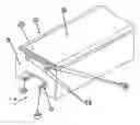
FIG. 1 shows fragmentary isometric view of the proposed pads giving details and view of upper part, middle part and lower part.
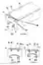
FIG. 2 shows front view of the impact pad along the arrow A shown in FIG. 1.
FIG. 3 shows the front view of the impact pad shown in FIG. 2.
FIGS. 4a to 4d show various types of the lower part namely the clamp arrangements used with different lengths and thickness.
FIG. 5 shows two segments of the proposed impact Pads.
DETAILED DESCRIPTION OF THE FIGURES OF THE ACCOMPANYING DRAWINGS
FIG. no 1 shows an isometric view of the impact pad (1) of the invention. It has three parts, namely an upper part (2), middle part (3) and lower part (4).
The upper part is made of material such as ultra high molecular weight polyethylene. (UHMPE).
As seen from a preferred embodiment of the drawings, the top surface of the upper part is slightly curved, (2A) and the under surface has two downwardly extending lugs, (2B, 2B).
These lugs are adapted to snugly fit into the corresponding grooves (3A), on the upper part of the middle part (3). The middle part is made of rubber.
The number of the grooves correspond to the number, shape and configuration of the downwardly extending lugs of the upper part. However, two lugs and the two complementary grooves are preferred for a proper fitting.
The lower part, (4) is the fastening means for fastening the impact pad on to the main support frame. It has longitudinal grooves (4A) and (4B) and can be of any convenient shape as shown in FIGS. 1, 2, 3, 4a 4b, 4c and 4d.
The different parts are preferably made separately assembled by a unique push-fit action.
If any one or more part/s is/are damaged, this can be easily replaced without having to discard the whole pad.
This saves cost and time and is also economical.
Claims
1. An impact pad comprising an upper part, a middle part, and a lower part, the upper part comprising a single piece with a plurality of protrusions on an under side thereof facing the middle part, such that said protrusions are adapted to fit into grooves provided on a top surface of the middle part, a bottom surface of the middle part including with lower part, the lower part comprising a clamp to fasten the impact pad on a main support frame with clamps.
2. The impact pad as claimed in claim 1, wherein the fastening arrangement is unique.
3. The impact pad as claimed in claim 1, wherein the push fit arrangement has different geometrical shapes and designs with similarly matching portion in rubber to fitting method by simple pushing.
4. The impact pad as claimed in claim 1, wherein the middle part/layer forms a selected design and push fit with upper part/layer is unique and can have different geometrical shapes and designs with similarly matching on the upper part/layer and process of fitting by push fit.
5. The impact pad as claimed in claim 1, wherein the upper part/layer is made of material such as Ultra High Molecular Weight Poly Ethylene (UHMWPE) and the middle part/layer is made of rubber. The lower part/layer has clamping arrangement for fastening the impact pad on the main support frame.
6. The impact pad as claimed in claim 1, wherein in preferred embodiments, the impact pads are manufactured in different lengths, thickness and shapes according to the particular requirement and all such embodiments are within the scope of the instant application.
7. In an optional embodiment, adhesive may be used between the upper part/layer and the middle part/layer.
8. (canceled)
Images & Drawings included:


Sources:
- United States Patent and Trademark Office - verify current appl. status at the USPTO↗
Recent applications in this class:
- » 20250116080 2025-04-10
A BAMBOO BASED CRASH BARRIER FOR ROADS OR HIGHWAYS - » 20220145558 2022-05-12
Road safety barrier assembly for detecting an impact of a vehicle - » 20210301485 2021-09-30
Guard rail barrier from recycled tires - » 20180327985 2018-11-15
FIBERGLASS GUARD RAIL - » 20180291576 2018-10-11
PLASTIC GUARDRAIL - » 20150337508 2015-11-26
Recycled tire rubber barrier modular system - » 20150259866 2015-09-17
Protective barrier - » 20140103278 2014-04-17
GUARDRAIL DEVICE FOR HIGHWAY - » 20120080654 2012-04-05
Visual highlight accessory for highway guardrails - » 20100118401 2010-05-13
Guardrail block and reflector system
Recent applications for this Assignee:
- » 20170267457 2017-09-21
WEAR-RESISTANT CERAMIC LINER WITH SNAP-LOCK FIXING ARRANGEMENT - » 20160340128 2016-11-24
CONVEYOR BELT SCRAPER - » 20160167892 2016-06-16
Belt scraper assembly - » 20150165482 2015-06-18
Trommel assembly - » 20150151924 2015-06-04
Belt scraper assembly - » 20140360842 2014-12-11
Belt scraper mounting - » 20140124416 2014-05-08
Screen panel with improved screening area - » 20140021107 2014-01-23
Screen panel - » 20130213863 2013-08-22
Screen panel with improved apertures - » 20130126397 2013-05-23
Screen panel