Hollow core waveguide for laser generation of ultrasonic waves
US20090285523A1
2009-11-19
12/121,559
2008-05-15
✅ Patent granted
US 7,734,133 B2
2010-06-08
-
-
Frank G Font | Robert Tavlykaev
2028-05-15
Abstract:
A laser transmission system.
Inventors:
- Marc Dubois 23 🇺🇸 Keller, TX, United States
- Thomas E. Drake, JR. 24 🇺🇸 Fort Worth, TX, United States
- Mark A. Osterkamp 5 🇺🇸 Weatherford, TX, United States
Assignee:
- LOCKHEED MARTIN CORPORATION 4,141 🇺🇸 Bethesda, MD, United States
Interested in similar patents?
Get notified when new applications in this technology area are published.
Classification:
G02B6/32 IPC
Light guides; Coupling light guides; Optical coupling means having lens focusing means positioned between opposed fibre ends
G02B6/4206 » CPC main
Light guides; Coupling light guides; Coupling light guides with opto-electronic elements; Packages, e.g. shape, construction, internal or external details the coupling comprising intermediate optical elements, e.g. lenses, holograms Optical features
B23K26/03 » CPC further
Working by laser beam, e.g. welding, cutting or boring; Positioning or observing the workpiece, e.g. with respect to the point of impact; Aligning, aiming or focusing the laser beam Observing, e.g. monitoring, the workpiece
B23K26/06 » CPC further
Working by laser beam, e.g. welding, cutting or boring; Positioning or observing the workpiece, e.g. with respect to the point of impact; Aligning, aiming or focusing the laser beam Shaping the laser beam, e.g. by masks or multi-focusing
B23K26/0884 » CPC further
Working by laser beam, e.g. welding, cutting or boring; Devices involving relative movement between laser beam and workpiece; Devices involving movement of the laser head in at least one axial direction in at least two axial directions in at least in three axial directions, e.g. manipulators, robots
G01N29/2418 » CPC further
Investigating or analysing materials by the use of ultrasonic, sonic or infrasonic waves; Visualisation of the interior of objects by transmitting ultrasonic or sonic waves through the object; Details, e.g. general constructional or apparatus details; Probes using optoacoustic interaction with the material, e.g. laser radiation, photoacoustics
G01N29/265 » CPC further
Investigating or analysing materials by the use of ultrasonic, sonic or infrasonic waves; Visualisation of the interior of objects by transmitting ultrasonic or sonic waves through the object; Details, e.g. general constructional or apparatus details; Arrangements for orientation or scanning by relative movement of the head and the sensor by moving the sensor relative to a stationary material
G02B6/12 IPC
Light guides of the optical waveguide type of the integrated circuit kind
G02B6/26 IPC
Light guides; Coupling light guides Optical coupling means
G02B6/42 IPC
Light guides; Coupling light guides Coupling light guides with opto-electronic elements
G01N29/00 IPC
Investigating or analysing materials by the use of ultrasonic, sonic or infrasonic waves; Visualisation of the interior of objects by transmitting ultrasonic or sonic waves through the object
G01H11/00 IPC
Measuring mechanical vibrations or ultrasonic, sonic or infrasonic waves by detecting changes in electric or magnetic properties
G01N24/00 IPC
Investigating or analyzing materials by the use of nuclear magnetic resonance, electron paramagnetic resonance or other spin effects
G01N29/04 IPC
Investigating or analysing materials by the use of ultrasonic, sonic or infrasonic waves; Visualisation of the interior of objects by transmitting ultrasonic or sonic waves through the object Analysing solids
G01N9/24 IPC
Investigating density or specific gravity of materials; Analysing materials by determining density or specific gravity by observing the transmission of wave or particle radiation through the material
Description
BACKGROUND
This disclosure relates to transmission systems for transmitting laser beams.
BRIEF DESCRIPTION OF THE DRAWINGS
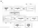
FIG. 1 is a schematic illustration of an exemplary embodiment of a laser transmission system.
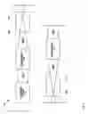
FIG. 2 is a schematic illustration of an exemplary embodiment of a laser ultrasound detection system that incorporates the laser transmission system of FIG. 1.
DETAILED DESCRIPTION
In the drawings and description that follows, like parts are marked throughout the specification and drawings with the same reference numerals, respectively. The drawings are not necessarily to scale. Certain features of the invention may be shown exaggerated in scale or in somewhat schematic form and some details of conventional elements may not be shown in the interest of clarity and conciseness. The present invention is susceptible to embodiments of different forms. Specific embodiments are described in detail and are shown in the drawings, with the understanding that the present disclosure is to be considered an exemplification of the principles of the invention, and is not intended to limit the invention to that illustrated and described herein. It is to be fully recognized that the different teachings of the embodiments discussed below may be employed separately or in any suitable combination to produce desired results. The various characteristics mentioned above, as well as other features and characteristics described in more detail below, will be readily apparent to those skilled in the art upon reading the following detailed description of the embodiments, and by referring to the accompanying drawings.
Referring initially to FIG. 1, an exemplary embodiment of laser transmission system 100 includes a laser beam source 102 having an output that is operably coupled to the input of a lens assembly 104. The output of the lens assembly 104 is operably coupled to the input of a first hollow core waveguide 106. The output of the first hollow core waveguide 106 is coupled to an end of an optical fiber 108. The other end of the optical fiber 108 is coupled to input of a second hollow core waveguide 110. The output of the second hollow core waveguide 110 is operably coupled to the input of a lens assembly 112.
In an exemplary embodiment, the laser beam source 102 may be a conventional laser beam source such as, for example, a laser beam capable of generating wavelengths within the middle of the infra red region such as, for example, in the 3 to 5 micron range. In an exemplary embodiment, the lens assemblies, 104 and 112, may be conventional lens assemblies suitable for focusing a laser beam. In an exemplary embodiment, the hollow core waveguides, 106 and 110, may be conventional hollow core waveguides such as, for example, metal, plastic and glass hollow core waveguides. In an exemplary embodiment, the diameter of the hollow core waveguides, 106 and 110, are significantly greater than the diameter of the optical fiber 108. In an exemplary embodiment, the diameter of the hollow core waveguides, 106 and 110, are larger than the diameter of the beam 102a at the ends of the hollow core waveguides positioned in opposing relation to the lens assemblies, 104 and 112, respectively, taking into account the length of the hollow core waveguides and the numerical aperture and diameter of the optical fiber 108. In an exemplary embodiment, the lengths of the hollow core waveguides, 106 and 112, are significant relative to the focal lengths of the lens assemblies, 104 and 112, such that the diameter of the laser beam 102a is significantly larger at the ends of the hollow core waveguides versus at the ends of the optical fiber 108.
In an exemplary embodiment, during the operation of the system 100, the laser beam source 102 generates a laser beam 102a that is then focused by the lens assembly 104. The focused laser beam 102a then passes into the hollow core waveguide 106 and enters into and through the end of the fiber 108. At the other end of the end of the fiber 108, the laser beam 102a exits and passes into and through the hollow core waveguide 110. As the laser beam 102a passes through and out of the hollow core waveguide, the laser beam spreads and is then focused by the lens assembly 112.
Referring now to FIG. 2, in an exemplary embodiment, the system 100 is incorporated into a laser ultrasound system 200 in which the hollow core waveguide 110 and lens assembly 112 are operably coupled to a motion control system 202 for controllably moving the hollow core waveguide and lens assembly relative to a work piece 204. A conventional optical detection system 206 is also provided proximate the work piece 204 that is operably coupled to a system controller 208. In an exemplary embodiment, the motion control system 202 may include, for example, a robotic arm.
In an exemplary embodiment, during the operation of the laser ultrasound system 200, the system 100 is operated by the system controller 208 to focus the laser beam 102a onto the surface of the work piece 204. In an exemplary embodiment, during the operation of the system 200, the motion control system 202 may be operated to position and orient the hollow core waveguide 110 and lens assembly 112 relative to one or more exterior surfaces of the work piece 204. Optical energy reflected by the exterior surfaces of the work piece 204 is then detected by the optical detection system 206 and processed by the system controller 208 in a well known manner to inspect the workpiece 204. The design and operation of using laser beam energy for laser ultrasound inspection of a work piece is considered well known to persons having ordinary skill in the art.
It is understood that variations may be made in the above without departing from the scope of the invention. Further, spatial references are for the purpose of illustration only and do not limit the specific orientation or location of the structure described above. While specific embodiments have been shown and described, modifications can be made by one skilled in the art without departing from the spirit or teaching of this invention. The embodiments as described are exemplary only and are not limiting. Many variations and modifications are possible and are within the scope of the invention. Accordingly, the scope of protection is not limited to the embodiments described, but is only limited by the claims that follow, the scope of which shall include all equivalents of the subject matter of the claims.
Claims
1. A system for transmitting laser beams, comprising:
a source of laser beams;
a first lens assembly operably coupled to the source of laser beams;
a first hollow core waveguide operably coupled to the first lens assembly;
an end of an optical fiber coupled to the first hollow core waveguide;
a second hollow core waveguide coupled to the other end of the optical fiber; and
a second lens assembly operably coupled to the second hollow core waveguide.
2. The system of claim 1, wherein the source of laser beams comprises a source of laser beams having wavelengths in the range of 3 to 5 microns.
3. The system of claim 1, wherein a refractive index of at least one of the first and second hollow core waveguides is about the same as a refractive index of the optical fiber.
4. The system of claim 1, wherein a length of at least one of the first and second hollow core waveguides range from about 5 to 100 times a focal length of at least one of the first and second lens assemblies.
5. The system of claim 1, further comprising a motion control system operably coupled to the second hollow core waveguide and the second lens assembly for controllably displacing the second hollow core waveguide and the second lens assembly with respect to a workpiece.
6. A method of transmitting a laser beam from a laser beam source to a work piece, comprising:
focusing the laser beam using a first lens assembly;
then transmitting the laser beam into and through a first hollow core waveguide;
then transmitting the laser beam into and through an end of an optical fiber;
then transmitting the laser beam out of an another end of the optical fiber;
then transmitting the laser into and through a second hollow core waveguide; and
then focusing the laser beam using a second lens assembly.
7. The method of claim 6, wherein the laser beam source comprises a source of laser beams having wavelengths in the range of 3 to 5 microns.
8. The method of claim 6, wherein a refractive index of at least one of the first and second hollow core waveguides is about the same as a refractive index of the optical fiber.
9. The method of claim 6, wherein a length of at least one of the first and second hollow core waveguides range from about 5 to 100 times a focal length of at least one of the first and second lens assemblies.
10. The method of claim 6, further comprising controllably displacing the second hollow core waveguide and the second lens assembly with respect to a workpiece.
11. A laser ultrasound system, comprising:
a source of laser beams;
a first lens assembly operably coupled to the source of laser beams;
a first hollow core waveguide operably coupled to the first lens assembly;
an end of an optical fiber coupled to the first hollow core waveguide;
a second hollow core waveguide coupled to the other end of the optical fiber;
a second lens assembly operably coupled to the second hollow core waveguide;
a motion control system operably coupled to the second hollow core waveguide and the second lens assembly for controllably positioning the second hollow core waveguide and the second lens assembly with respect to a work piece;
an optical detection system positioned proximate the work piece for detecting optical energy reflected off of the work piece; and
a controller operably coupled to the source of laser beams, the motion control system, and the optical detection system for controlling the operation of the source of laser beams, the motion control system, and the optical detection system and for processing the optical energy reflected off of the work piece to determine one or more characteristics of the work piece.
12. The system of claim 11, wherein the source of laser beams comprises a source of laser beams having wavelengths in the range of 3 to 5 microns.
13. The system of claim 11, wherein a refractive index of at least one of the first and second hollow core waveguides is about the same as a refractive index of the optical fiber.
14. The system of claim 11, wherein a length of at least one of the first and second hollow core waveguides range from about 5 to 100 times a focal length of at least one of the first and second lens assemblies.
15. A method of determining one or more characteristics of a work piece, comprising:
generating a laser beam;
focusing the laser beam using a first lens assembly;
then transmitting the laser beam into and through a first hollow core waveguide;
then transmitting the laser beam into and through an end of an optical fiber;
then transmitting the laser beam out of an another end of the optical fiber;
then transmitting the laser into and through a second hollow core waveguide; and
then focusing the laser beam using a second lens assembly;
controllably displacing the second hollow core waveguide and the second lens assembly with respect to the work piece;
impacting one or more surfaces of the work piece with the laser beam;
monitoring reflection of the laser beam off of one or more surfaces of the work piece; and
processing the monitored reflections to determine one or more characteristics of the work piece.
16. The method of claim 15, wherein the laser beam source comprises a source of laser beams having wavelengths in the range of 3 to 5 microns.
17. The method of claim 15, wherein a refractive index of at least one of the first and second hollow core waveguides is about the same as a refractive index of the optical fiber.
18. The method of claim 15, wherein a length of at least one of the first and second range from about 5 to 100 times a focal length of at least one of the first and second lens assemblies.
19. The method of claim 15, further comprising controllably displacing the second hollow core waveguide and the second lens assembly with respect to a workpiece.
Images & Drawings included:

Sources:
- United States Patent and Trademark Office - verify current appl. status at the USPTO↗
Recent applications in this class:
- » 20250284072 2025-09-11
MULTIPLEXED SINGLE-PHOTON GENERATOR AND ASSOCIATED METHODS - » 20250258346 2025-08-14
HYBRID OPTIC WAVEGUIDE INPUT/OUTPUT (IO) AND ELECTRIC IO INTEGRATION FOR HIGH PERFORMANCE CHIPS - » 20250237820 2025-07-24
OPTICAL CONNECTOR WITH KINEMATIC COUPLING - » 20250216625 2025-07-03
SEMICONDUCTOR PACKAGE - » 20250216624 2025-07-03
Comb Laser Source Architectures for Photonic integrated Circuits - » 20250208360 2025-06-26
SYSTEM AND APPARATUS FOR OPTICAL COUPLING - » 20250180832 2025-06-05
OPTICAL DEVICE - » 20250172767 2025-05-29
WAFER-SCALE WAVEGUIDES FOR INTEGRATED TWO-DIMENSIONAL PHOTONICS - » 20250164708 2025-05-22
ELECTRONIC DEVICE FOR PROVIDING AUGMENTED REALITY AND METHOD BY WHICH ELECTRONIC DEVICE COMPENSATES FOR IMAGE - » 20250164707 2025-05-22
STRUCTURES FOR A PHOTONICS CHIP THAT ENABLE EXTERNAL COMMUNICATION
Recent applications for this Assignee:
- » 20250235975 2025-07-24
SYSTEMS AND METHODS FOR LOW TEMPERATURE SANDING AND POLISHING - » 20250223031 2025-07-10
THRUST CONTROL FOR GROUND NAVIGATION OF AERIAL VEHICLES - » 20250223029 2025-07-10
HYBRID PITCH BEARING FOR RIGID ROTOR - » 20250197000 2025-06-19
COMMONLY MANUFACTURED ROTOR BLADE - » 20250193770 2025-06-12
Mesh Network Management Of Space-Deployed Systems - » 20250187752 2025-06-12
OPTICAL MEASUREMENT SYSTEM TO LAND AN AERIAL VEHICLE - » 20250178721 2025-06-05
TIP END JOINT ARRANGEMENT FOR A ROTOR BLADE WITH RECONFIGURABLE ATTRIBUTES FOR STRUCTURAL AND AERODYNAMIC TUNING - » 20250167724 2025-05-22
Rigid-Framed Flexible Panel Solar Array - » 20250146532 2025-05-08
STRESS REDUCING FASTENER ASSEMBLY - » 20250145475 2025-05-08
Tailorable Polyorbital-Hybrid Ceramics