HYDROGEN GENERATOR SYSTEM
US20090288947A1
2009-11-26
12/244,026
2008-10-02
Abstract:
A hydrogen generator apparatus for a vehicle a reservoir for electrolyte, and electrolyte chamber, an electrolyte feed line to the electrolyte chamber, at least one pair of electrodes chamber, a conduit from the electrolyte chamber to the air line of the engine, the electrodes being vertically disposed in the electrolyte chamber and being between 0.125 and 0.2 inch apart; a voltage supply to the electrodes in response to adjustment to the throttle of the engine and being determined by a signal from the spark plug/injector signals of the engine, the amount of hydrogen (and oxygen) produced being controlled to prevent stoichiometric excess having regard to the requirement of the engine for the combination of fuel and the gases, and a supply of fresh air to the electrolytic chamber to dislodge hydrogen and oxygen clinging to the electrodes.
Interested in similar patents?
Get notified when new applications in this technology area are published.
Classification:
C25B9/17 » CPC main
Cells or assemblies of cells; Constructional parts of cells; Assemblies of constructional parts, e.g. electrode-diaphragm assemblies; Process-related cell features Cells comprising dimensionally-stable non-movable electrodes; Assemblies of constructional parts thereof
F02M25/12 » CPC further
Engine-pertinent apparatus for adding non-fuel substances or small quantities of secondary fuel to combustion-air, main fuel or fuel-air mixture adding acetylene, non-waterborne hydrogen, non-airborne oxygen, or ozone the apparatus having means for generating such gases
Y02T10/12 » CPC further
Road transport of goods or passengers; Internal combustion engine [ICE] based vehicles Improving ICE efficiencies
Y02T10/12 » CPC further
Road transport of goods or passengers; Internal combustion engine [ICE] based vehicles Improving ICE efficiencies
C25B9/00 IPC
Cells or assemblies of cells; Constructional parts of cells; Assemblies of constructional parts, e.g. electrode-diaphragm assemblies; Process-related cell features
Description
FIELD OF THE INVENTION
This invention relates to a hydrogen generator system for internal combustion engines, whether stationary, in vehicles or marine vessels.
BACKGROUND OF THE INVENTION
The addition of a mixture of hydrogen and oxygen to the air-intake or into a conduit leading to the air-intake, of an internal combustion engine is well known but to the Applicants' knowledge a truly successful system has not yet been devised and it is the main object of the present invention to provide a system which promises to increase the efficiency of an engine to a great degree—for example the system can result in the doubling of a vehicle's fuel mileage.
The closest prior art known to the Applicant is U.S. Pat. No. 4,442,801 which describes a unit having a reservoir for electrolyte leading to an electrolyte chamber with horizontal electrodes, the voltage supply to the electrodes being derived from an alternator and is modulated by means of a variable resistor operated by the throttle. A pump is provided to blow a pusher gas such as air or preferable exhaust gases to sweep hydrogen and oxygen from the electrodes surfaces.
The Applicant has made some major and some minor changes to this prior art with the result that exceptionally decreased fuel consumption has been achieved.
BRIEF DESCRIPTION OF THE DRAWINGS
The system will be described in connection with the attached drawings, in which:
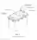
FIG. I illustrates a hydrogen generator assembly;
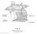
FIG. II illustrates a hydrogen generator assembly without a chamber;
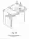
FIG. III illustrates a hydrogen generator assembly in cut-away view;
FIG. IV is a block diagram illustration of the system;
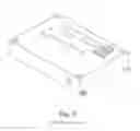
FIG. V illustrates a controller assembly; and
FIG. VI illustrates an envelope logic control module.
THE INVENTION
According to the invention a hydrogen generator apparatus for a vehicle including a reservoir for electrolyte, and electrolyte chamber, an electrolyte feed line to the electrolyte chamber, at least one pair of electrodes in the electrolyte chamber, and a conduit from the electrolyte chamber to the air intake of the engine is characterized by the electrodes being vertically disposed in the electrolyte chamber, the electrodes being between 0.125 and 0.2 inch apart and preferably 0.185 inch, a voltage supply to the electrodes in response to adjustment to the throttle of the engine signal from injectors and being determined by a signal from the oil pressure sensor of the engine or similar signal showing that the engine is running, the amount of hydrogen (and oxygen) produced being controlled to prevent stoichiometric excess having regard to the requirement of the engine for the combination of fuel and the gases, and a supply of fresh air or exhaust gas to the electrolytic chamber to dislodge hydrogen and oxygen clinging to the electrodes.
The electrodes are preferably spot welded together on a simple angle header.
A reverse polarity is imposed on the electrodes. The period of polarity change may be of the order of three hours during driving, during which a cleaning cycle takes place for 2 to 10 minutes.
The positive signal from the oil pressure sensor or signal from the fuel injector coils allow the LCM to control the electrical current flow to the electrodes to a predetermined extent to avoid overproduction of hydrogen and oxygen which would otherwise have to be evacuated to atmosphere—which is a source of hazard. In addition any excess of the gases in the system can also lead to a hazardous situation.
In a refinement of the invention a single pump maybe provided which controls the flow of fresh air and electrolyte to the electrolyte chamber. This may be effected by the provision of a two-valve system ( one pre- and one post-pump).
The two valves and pump, together with a filter may be located in a separate assembly.
Whilst it is not necessary to provide constant electrolyte circulation, the one pump arrangement accomplishes three system functions during three modes of operation as follows:
The Hydrogen Generator Assembly (HGA)
Reference is made to Figure I, II and III, which is computer generator models of the HGA and Fig. IV is a block diagram of the Hydrogen Generator System (HGS).
Generate Mode:
The pump is activated and both valves are in their default de-energized position. Fresh air or pusher gas is brought in through Valve #2 and out via the manifold to serve as pusher gas. Since this is the mode that is used most often, the valves are designed so their solenoids are in their de-energized state to use as little electricity as possible.
Cleansing Mode:
The pump is activated and Valve #1 is de-energized. This opens the path to allow the pump to draw electrolyte from the bottom of the chamber. The electrolyte passes through Valve #1, the pump, energized Valve #2 and the filter and finally the manifold at the bottom of the chamber.
Rinse Cycle:
At the option of the operation, the ball valve in the drain output line from the bowl is opened and the operator turns the switch to rinse for 10 to 20 seconds to rinse the filter and the bottom of the chamber. The operator will usually have a container, collect the ejected water.
Drain Mode:
The pump is activated and both Valve #1 is energized and Valve #2 are ok as is. This opens the path to allow the pump to draw electrolyte from the bottom of the chamber. The electrolyte passes through energized Valve #1, the pump, energized Valve #2 and out through the drain hose. Since the operator has commanded the system to drain, upon sensing a low level in the chamber, a logic control module (LCM) will instruct the reservoir pump to activate as well. This process will continue until the operator returns the drain button or both reservoir and chamber are empty at which time the pumps will de-activate and the valve will de-energize automatically.
The system of the invention may be incorporated into a compact unit which is easy to assemble and install.
A manifold assembly may be provided to disperse the air/pusher gas over a maximum area of the electrodes.
The logic control module is provided to monitor and control all functions of the system by means of sensors and commands, and is programmed to handle the majority of tasks automatically and to disallow tasks that may cause problems such as temperature, electrolyte level and oil pressure are as predetermined. Other parameters such as clock and memory systems may be incorporated to schedule events such as polarity changes, electrolyte purification and others.
Components & Criteria
The hydrogen generator system consists of the following 4 main sub-assemblies, and support components, as generally depicted in Figure IV:
-
- Hydrogen Generator Assembly (HGA)
- Logic Control Module (LCM)
- Control Valve Assembly (CVA)
- Reservoir Assembly
- Instrument & Control Panel (I&CP)
- Potentiometer
- Connection to Engine Control Circuit
- Harness Assembly (7)
- Hoses
The components shall be designed for mass production. Each HGA series and associated components shall be designed and sized for specific vehicle models and installation. Brief descriptions of each component in the major sub-assemblies are:
Hydrogen Generator Assembly (HGA)
-
- The Housing is made from injection molded, high strength plastic. It provides for indexing and proper location for the electrode assemblies and a complete seal between housing and cover to prevent any leakage of hydrogen gas. The housing serves as the container for the electrolyte.
- The Cover is also made from injection molded, high strength plastic. It provides for the mounting of the Electrode Assembly by the 2 electrode studs (+) and (−) to the electrode assembly and access hole for mounting the level sensor for the chamber.
- The Electrode Assembly is made up from stainless steel electrode blades (typically 20), spot welded together on a stainless steel header. A terminal stud is welded to the header to transfer the current to the electrode blades. Two electrodes (20 plates) are assembled together with plastic spacers and pins to make up the complete electrode assembly.
- The Manifold Assembly is manufactured and spot welded together from stainless steel sheets and spacers. The top sheet is equipped with a number of small holes, which direct air or pusher gas up between the electrode blades and move the attached hydrogen & oxygen bubbles from the electrode blades. The manifold assembly has a tubular nipple to receive the pusher gas. The manifold is attached to the electrode assembly by 4 screws to the lower spacers on both sides of the electrode assembly.
- The Level, Temperature Sensor is designed to send signals to the LCM sensing:
- a) The level of the electrolyte in the chamber.
- b) The temperature of the electrolyte in the chamber.
- The Heater Assembly is a Cal-rod type heater and is designed to heat the electrolyte in the chamber and allow the LCM to control the electrolyte temperature at pre-selected temperatures.
The Control Valve Assembly (CVA) is designed to house the pump assembly, 2 valve assemblies and a filter assembly. The control valve housing is made from injection molded, high strength materials. All the inter connecting porting between components are all achieved by internal drilled holes to minimize fittings and change for leakage.
-
- The Pump Assembly is a screw type pump element driven by a 12V motor, running at constant speed and delivering approximately 3@ PM at approximately 10 PSI. The screw is made of silicone bronze material and produced as investment cast parts.
- The Valve Assemblies are solenoid operated, 2 position and powered by 12 volts. The controls of the solenoids by the LCM are provided with a holding circuit so the solenoids draw very little current when energized. The poppet in the valve is made from rubber to provide positive seal in both positions.
- The Filter Assembly is made from stainless steel with a 2 micron porosity. The fluid is introduced into the filter in a rotating motion. This spins out the solids against the filter walls. The filter element is held in the control valve body by the filter bowl, which is designed to collect the solids collected from the electrolyte during the operation of the HGS.
The Logic Control Module (LCM) (see Figure VI) is a self-contained unit that regulates all logic, command and sensing signals between the HGA, potentiometer, oil pressure sensor, Instrument & Control Panel (I& CP) reservoir and Engine Control Circuits.
Its circuitry and components are housed in a cast aluminum body. The Printed Circuit Board Assembly (PCBA) with all its components is housed in this casting with a thin sheet metal cover. The aluminum housing is designed with multiple fins to provide the necessary cooling of the components and circuit of the LCM. The LCM control and distribute signals and power to all the components in the HGA. The main functions of the LCM are:
-
- 1. Control and distribute current to the electrodes. The current may be set by the Micro Processor, varying from 0 amp to 50 AMP.
- 2. Change the polarity of the circuit for the current to the electrodes. The time between changes is programmed by the M.C. It is currently set to be 3 hours.
- 3. Program and set the functions for varying the current to the electrodes as a function of the speed of the vehicle or RPM of the engine.
- 4. Control/time the cleaning cycle of the water in the chamber of the HGA.
- 5. Monitor the water level and temperature in the chamber of the HGA.
- 6. Control the replenishing of water to the chamber of the HGA from the Reservoir as the water is being depleted by the production of hydrogen gas.
- 7. Monitor the water level and temperature in the Reservoir.
- 8. Take the command signals from the Controller (CA) to turn on the LCM operations as well as the function to drain water from the Chamber/Reservoir.
- 9. Provide signals for the (4) LED displays on the Controller to display status of;
- a) Current used by Electrode
- b) Water Temperature in chamber
- c) Water Level in chamber
- d) Water Level in Reservoir.
- The heavy current for the Electrode is controlled by a Field Effect Transistor (FET) which utilizes Pulse Width Modulation (PWM) to control the average power delivered to the electrode. This component is the one that generates most of the heat within the LCM.
- The circuit is designed to provide polarity reversal of the electrode current, utilizing 3 relays. These are used in lieu of FET's in order to minimize the heat generated by the circuit and the components.
- The unique design of the PCBA and its housing allows the electrode FET, the only component that generates significant heat, to be mounted directly to the metal surface of the aluminum housing. A small surface of the housing, sufficient for the mounting of the FET, protrudes through the circuit board to connect with the rear surface of the FET. This greatly improves the heat exchange between the FET and the housing, negating the need for a fan and forced air over the fins of the housing. The component in the circuit of timing and polarity change is made by a micro processor in the LCM. This is explained later.
- The 2 valves, pump and filter are placed in a separate assembly. This has resulted I the components of the HGA to be manufactured very simple and cheaply.
The Controller Assembly (CA) shall be designed to fit in a convenient and ergonomically correct location on the dashboard. The panel shall be designed and styled for each vehicle type. The wire harness from the panel to the LCM shall be drawn through a small hole in the firewall if possible. The features on the CA are as follows:
-
- System “ON/OFF” switch: The operator uses this switch to manage the production of Hydrogen.
- Function “Auto/Drain” button: The operator uses this button to enable the drain function. The operator leaves this button in the “Auto” mode until the “drain” function is required.
- Four color—coded rows of display lights are mounted flush to the CA. The operator can monitor, at a glance, the following:
- Electro Current Level (Amps)
- Electrolyte level—Chamber
- Electrolyte level—Reservoir
- Electrolyte temperature—Chamber
The Reservoir Assembly (RA) is a 3 gallon tank holding the reserve water required for approximately 1,500 miles of travel. The RA consists of the plastic tank, a level/temperature sensor and a pump assembly. The pump delivers the desired amount of water as necessary to the HGA to maintain the appropriate level of water for efficient operation of the electrodes. The level Sensor and the Pump Assembly are identical to those used with-in the CVA. These components are controlled by the LCM and monitored by its micro controller.
The Cables: there are 7 cables with connectors that connect all the major components of the HGS on the truck/vehicle. Three of the cables go from the LCM to HGA, the CVA and RA. One cable goes from LCM to the battery and 2 cables go from LCM to the electrical system of the vehicle.
The cables are built with water tight connectors and cables and wires approved by the automotive industry.
The Hoses shall be automotive grade rubber and will be used as follows:
-
- To conduit the electrolyte from the reservoir to the chamber
- To conduit the electrolyte from the drain plug to the ground
- To conduit the electrolyte from the bottom of the chamber to Valve #1
- To conduit the generated gas mixture from the HGA to the vehicle's air intake apparatus
General Description of Operation
The typical operation and functions of the HGS and it's various components are envisioned to be as follows, commencing with the first HGS start-up:
-
- With the vehicle's engine not running and the System switch in the “Off” position (and the Function button in the “Auto” position) the operator fills the reservoir with clean tap water or electrolyte. The operator then turns the System switch “On”. The LCM reads the signal from the chamber's level sensor and commands the reservoir pump to transfer electrolyte to the chamber. Even thought the System switch is turned “On”, the HGA will not try to produce Hydrogen with an empty chamber since the vehicle's engine is not running. The level sensor in the chamber will signal the LCM to automatically turn off the reservoir pump when the chamber is full. The operator then refills the reservoir with electrolyte. As good practice, the operator should refill the reservoir each time the gasoline tank is filled.
- NOTE: the level sensor in the chamber signals the LCM to command the reservoir pump to turn ON and refill the chamber whenever the electrolyte level in the chamber is low (and the System switch is “On”).
- The HGS is now ready to produce Hydrogen (as soon as the engine is running).
- With the System switch “On” and the Function button on “Auto”, the operator starts the vehicle and steps on the throttle. The oil pressure sensor reads positive pressure or similar circuit indicate engine is running and commands the LCM to deliver current to the Electrode Assemblies in direct proportion to the throttle position (according to signals from the engine circuits) thus generating Hydrogen and Oxygen. Simultaneously, the LCM activates the valve for pusher gas circulation in the HGA.
- The circulating pusher gas travels through the manifold and is directed upward through the Electrode Assemblies dislodging the Hydrogen bubbles that have collected on the electrodes. At the top of the chamber, the gas mixture collects and is delivered through a large conduit directly into the air stream of the carburetor or turbo in case of diesel engines. Hydrogen is not stored anywhere in the system.
- During operation, the operator will be provided, via the display on the dashboard, constant/real-time monitoring of the Electrolyte levels in the reservoir and chamber, the temperature of the electrolyte in the chamber and the current flowing to the electrode.
- When refilling the reservoir with electrolyte it is important to make sure that the electrolyte is clean and without any impurities.
- When parking or storing the vehicle in cold weather (below freezing) for long periods of time, the operator would be advised to drain the electrolyte from the chamber and the reservoir. To drain the electrolyte, you first ensure that they System switch (on the CA) is “Off” and then turn the Function button to “Drain”. The electrolyte will be pumped from the chamber onto the ground or into a container. When the chamber's level sensor senses the low level, the LCM will read the signal and command the reservoir's pump to transfer electrolyte to the chamber. This will continue until both the reservoir and the chamber are empty. To drain the system in cold climates is not extraordinary, but just one more in a series of precautions that must be taken for any vehicle that is left in cold weather.
- NOTE: When dumping the electrolyte from the system, it may be collected and reused. It is to be dumped on the ground, make sure that the vehicle is parked in a place where the electrolyte will run off without doing any damage.
- With the vehicle's engine not running and the System switch in the “Off” position (and the Function button in the “Auto” position) the operator fills the reservoir with clean tap water or electrolyte. The operator then turns the System switch “On”. The LCM reads the signal from the chamber's level sensor and commands the reservoir pump to transfer electrolyte to the chamber. Even thought the System switch is turned “On”, the HGA will not try to produce Hydrogen with an empty chamber since the vehicle's engine is not running. The level sensor in the chamber will signal the LCM to automatically turn off the reservoir pump when the chamber is full. The operator then refills the reservoir with electrolyte. As good practice, the operator should refill the reservoir each time the gasoline tank is filled.
Annexed hereto as Appendix A are road test data using the HGA of the invention on a Ford F350 van.
A block diagram of the HGA follows this Appendix A.
A logic control scheme for the CVA is annexed after the block diagram.
Claims
1. A hydrogen generator apparatus for a vehicle including a reservoir for electrolyte, and electrolyte chamber, an electrolyte feed line to the electrolyte chamber, at least one pair of electrodes chamber, a conduit from the electrolyte chamber to the air line of the engine, the electrodes being vertically disposed in the electrolyte chamber and being between 0.125 and 0.2 inch apart; a voltage supply to the electrodes in response to adjustment to the throttle of the engine and being determined by a signal from the spark plug/injector signals of the engine, the amount of hydrogen (and oxygen) produced being controlled to prevent stoichiometric excess having regard to the requirement of the engine for the combination of fuel and the gases, and a supply of fresh air to the electrolytic chamber to dislodge hydrogen and oxygen clinging to the electrodes.
2. A hydrogen generator apparatus according to claim 1 in which the electrodes are 0.185 inch apart.
3. A hydrogen generator apparatus according to claim 1 in which the electrodes are spot welded together on an angle header.
4. A hydrogen generator apparatus according to claim 1 in which a reverse polarity is imposed on the electrodes.
5. A hydrogen generator apparatus according to claim 4 in which the period of polarity change is of the order of three hours during driving.
6. A hydrogen generator apparatus according to claim 4 including a cleaning cycle for 10 minutes.
7. A hydrogen generator apparatus according to claim 1 in which the positive signal from the oil pressure sensor controls the electrical current flow to the electrodes to a predetermined extent to avoid overproduction of hydrogen and oxygen.
8. A hydrogen generator apparatus according to claim 1 in which a single pump is provided which controls the flow of fresh air and electrolyte to the electrolyte chamber.
9. A hydrogen generator apparatus according to claim 8 including the provision of a two-valve system (one pre- and one post-filter).
10. A hydrogen generator apparatus according to claim 9 in which the two valves and pump, together with a filter are located in a separate assembly.
Images & Drawings included:


Sources:
- United States Patent and Trademark Office - verify current appl. status at the USPTO↗
Similar patent applications:
- » 20210139324
Hydrogen generation system, power generation system, hydrogen generation method, and power generation method - » 20220316075
Method for controlling hydrogen generation system, and hydrogen generation system - » 20100183928
Hydrogen generation system, fuel cell system, and method for operation of hydrogen generation system - » 20240333195
Greenhouse integrated with PVT panel based power generation and energy storage system and vacuum solar collector based thermal power generation system and hydrogen generation system - » 20160168736
SIGNAL GENERATION SYSTEM FOR A HYDROGEN GENERATION SYSTEM - » 20170130350
Signal Generation System For A Hydrogen Generation System - » 20110143240
Hydrogen Generation System, Method for Generating Hydrogen Using Solid Hydrogen Fuel and Method for Providing Hydrogen for Fuel Cell Using the Same - » 20130004800
HYDROGEN GENERATION SYSTEM AND METHOD FOR GENERATING HYDROGEN FOR MOBILE AND POWER GENERATOR - » 20110180396
HYDROGEN GENERATOR SYSTEM FOR A CATALYTIC HYDROGEN BURNER - » 20230268532
A Hydrogen Generation Electricity System for Producing Electricity from Hydrogen Using a Hydrogen Carrier Substance and a Method for Operating the Hydrogen Generation Electricity System
Recent applications in this class:
- » 20240287688 2024-08-29
GAS PRODUCER AND METHOD OF USE - » 20240175145 2024-05-30
LIGHTWEIGHT ELECTROLYZER WITH A PLUG-IN MODULE - » 20230010993 2023-01-12
CARBON DIOXIDE EXTRACTION ELECTROLYSIS REACTOR - » 20220403534 2022-12-22
Chemical solution production - » 20220298654 2022-09-22
Compact hydrogen-oxygen generator - » 20220186386 2022-06-16
ELECTROLYZER WITH IMPROVED ELECTRODE STRUCTURE - » 20120279871 2012-11-08
Hydrogen gas generator - » 20120115071 2012-05-10
SYSTEM FOR CONVERTING ENERGY WITH AN ENHANCED ELECTRIC FIELD - » 20120080311 2012-04-05
Non metalic salt chlorinator for spa or swimming pool - » 20120061251 2012-03-15
Mixed Oxidant Electrolytic Cell