Method for regulating the level of a section of an oil tray comprising at least two sections
US20090314580A1
2009-12-24
12/442,420
2007-09-03
✅ Patent granted
US 8,534,425 B2
2013-09-17
WO; PCT/EP2007/059182; 20070903
WO; WO2008/037566; 20080403
William A Rivera | Michael Riegelman
Davis & Bujold, PLLC
2029-03-02
Abstract:
A method of regulating the oil level in a section of an oil sump of a splash-lubricated transmission that has at least first and second oil sump sections that are separated by a baffle plate (2). The oil sprayed from a gearwheel (1), that is immersed in one oil sump section, is specifically deflected into an adjacent oil sump section.
Assignee:
- ZF FRIEDRICHSHAFEN AG 3,767 🇩🇪 Friedrichshafen, Germany
Applicant:
Interested in similar patents?
Get notified when new applications in this technology area are published.
Classification:
F16H57/0447 » CPC main
General details of gearing; Features relating to lubrication or cooling or heating Control of lubricant levels, e.g. lubricant level control dependent on temperature
F16H57/0423 » CPC further
General details of gearing; Features relating to lubrication or cooling or heating; Guidance of lubricant on or within the casing, e.g. shields or baffles for collecting lubricant, tubes, pipes, grooves, channels or the like Lubricant guiding means mounted or supported on the casing, e.g. shields or baffles for collecting lubricant, tubes or pipes
F16H57/0453 » CPC further
General details of gearing; Features relating to lubrication or cooling or heating; Lubricant storage reservoirs, e.g. reservoirs in addition to a gear sump for collecting lubricant in the upper part of a gear case Section walls to divide a gear sump
F16H57/0457 » CPC further
General details of gearing; Features relating to lubrication or cooling or heating Splash lubrication
F16N7/26 IPC
Arrangements for supplying oil or unspecified lubricant from a stationary reservoir or the equivalent in or on the machine or member to be lubricated the lubricant being conveyed from the reservoir by mechanical means Splash lubrication
Description
This application is a National Stage completion of PCT/EP2007/059182 filed Sep. 3, 2007, which claims priority from German patent application serial no. 10 2006 045 240.2 filed Sep. 26, 2006.
FIELD OF THE INVENTION
The present invention concerns a method for regulating the oil level in a section of an oil sump of a splash-lubricated transmission that comprises at least two oil sump sections. In addition, the invention concerns a device for regulating the oil level in a section of an oil sump of a splash-lubricated transmission that comprises at least two oil sump sections, and in particular a device for implementing the method according to the invention.
BACKGROUND OF THE INVENTION
Within a splash-lubricated transmission, in particular a transmission of step-down design, the various diameters of the gearwheels involved result in varying immersion levels of the gearwheels in the oil sump. If a pair of engaging gears is not immersed in the oil sump, or only insufficiently so, then adequate lubrication and cooling in the tooth engagement area is not ensured and, disadvantageously, this deficient lubrication results in premature wear of the running gearteeth.
From the prior art it is known, in order to raise or lower the oil level specifically in particular sections of the oil sump, to use baffle plates to produce individual oil sump sections in which the oil level can be raised or lowered for example by virtue of the housing wall or by means of grooves, but this solution, disadvantageously, entails additional costs.
SUMMARY OF THE INVENTION
The purpose of the present invention is to indicate a method for regulating the oil level in a section of an oil sump of a splash-lubricated transmission that comprises at least two oil sump sections, which ensures adequate lubrication and cooling of the gearwheels of the transmission. In addition, a device for regulating the oil level in a section of an oil sump that comprises at least two oil sump sections is provided, which is suitable for implementing the method according to the invention.
Accordingly, to regulate the oil level in a section of an oil sump comprising at least two oil sump sections, it is proposed that the oil splashing off a gearwheel immersed in one section of the oil sump is specifically deflected into another oil sump section. According to the invention the oil splashing off a gearwheel immersed in the sump is deflected into an adjacent oil sump section, these two sections being separated by a baffle plate, the oil passing through the baffle plate via an opening located above the desired oil level.
To deflect the splashing oil a deflector device is provided, preferably arranged directly on the baffle plate under the gearwheel from which the oil is coming. Oil is drawn out of the sump by the rotating gearwheel and flung off radially. It is then deflected upward and to the side by the deflector device, which is preferably formed as a bowl, so that the oil passes through the opening in the baffle plate to the back of the latter. The deflector device can also be made in some other suitable form.
Thanks to the concept according to the invention sufficient lubrication and cooling of the gearwheels of a splash-lubricated transmission is ensured in a simple and inexpensive manner.
BRIEF DESCRIPTION OF DRAWINGS
Below, an example embodiment of the invention is explained in more detail with reference to the attached figures, which show:
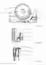
FIG. 1: Schematic front view of the device according to the invention for regulating the oil level in a section of an oil sump that comprises at least two oil sump sections;
FIG. 2: Schematic side view of the device according to the invention for regulating the oil level in a section of an oil sump that comprises at least two oil sump sections; and
FIG. 3: Schematic view of the device according to the invention for regulating the oil level in a section of an oil sump that comprises at least two oil sump sections, seen from above.
DETAILED DESCRIPTION OF THE PREFERRED EMBODIMENTS
FIGS. 1, 2 and 3 show a gearwheel 1 which rotates in the direction indicated by the arrow in a first oil sump section of a splash-lubricating oil sump, the first oil sump section being separated from a second oil sump section by a baffle plate 2. According to the invention, an opening 3 is provided in the baffle plate 2 above the oil level desired in the second, adjacent oil sump section, through which the splashed oil is deflected into the second oil sump section.
A preferably bowl-shaped deflector device 4 is provided to deflect the splashed oil, and is positioned directly on the baffle plate 2 under the gearwheell from which the oil is coming. Oil is drawn out of the sump by the gearwheel, directed radially, and deflected by the deflector device upward and to the side so that it passes through the opening 3, to the back of the baffle plate 2 and into the adjacent oil sump section. The direction of movement of the oil is indicated in the figures by the arrows 5.
Indexes
1 Gearwheel
2 Baffle plate
3 Opening
4 Deflector device
5 Oil movement direction
Claims
1-5. (canceled)
6. A splash-lubricated transmission having an oil sump with at least first and second oil sump sections, the first oil sump section being separated from the second oil sump section by a baffle plate (2) that extends vertically, and a rotating gearwheel (1) being arranged in the first oil sump section, the baffle plate (2) having an opening (3) above an oil level desired in the second oil sump section, and a deflector device (4) being provided in the first oil sump section to deflect oil flung off radially from the gearwheel (4) to a side, through the opening (3) in the baffle plate (2) and into the second oil sump section.
7. The transmission according to claim 6, wherein the deflector device (4) for the splashed oil is arranged directly on the baffle plate (2) under the gearwheel (1) from which the oil is coming.
8. The transmission according to claim 7, wherein the deflector device (4) is in the form of a bowl.
9. A splash-lubricated transmission comprising:
an oil sump having at least first and second oil sump sections separated by a baffle plate (2) that extends vertically within the oil sump to accommodate oil at a desired level in the second oil sump section, and the baffle plate (2) having an opening (3) that is located above the desired level of oil in the second oil sump section;
a rotating gear wheel (1) being immersed in oil that accommodated within the first oil sump section; and
a deflector device (4) being located within the first oil sump section to divert oil that is radially propelled by the rotating gear wheel (4) through the opening (3) in the baffle plate (2) and into the second oil sump section.
10. The transmission according to claim 9, wherein the deflector device (4) is located on the baffle plate (2) under the gear wheel (1) from which the oil is radially propelled.
11. The transmission according to claim 10, wherein the deflector device (4) has the form of a bowl.
12. A method of regulating an oil level in an oil sump section of a transmission having an oil sump with at least first and second oil sump sections, the first oil sump section being separated from the second oil sump section by a baffle plate (2) that extends vertically, and a rotating gearwheel (1) being arranged in the first oil sump section, the baffle plate (2) having an opening (3) above an oil level desired in the second oil sump section, and a deflector device (4) being provided in the first oil sump section to deflect oil flung off radially from the gearwheel (4) to a side, through the opening (3) in the baffle plate (2) and into the second oil sump section, the method comprising the step of:
directing the oil flung off the gearwheel (1) immersed in the first oil sump section through the opening (3) in the baffle plate (2) and into the second oil sump section.
Images & Drawings included:

Sources:
- United States Patent and Trademark Office - verify current appl. status at the USPTO↗
Recent applications in this class:
- » 20240175487 2024-05-30
CONTROL SYSTEM FOR CONTROLLING AN OIL LEVEL IN A GEARBOX OF A VEHICLE, ASSOCIATED GEARBOX ASSEMBLY AND VEHICLE - » 20230175581 2023-06-08
Systems and methods for providing adjustable lubrication to a tandem axle - » 20210404546 2021-12-30
Systems and methods for providing adjustable lubrication to a tandem axle - » 20200347928 2020-11-05
Gear unit with reduced power loss, operating method and industrial application - » 20200200258 2020-06-25
Integrated flow control member - » 20200182347 2020-06-11
Transmission and motor vehicle - » 20190257408 2019-08-22
OIL CONVEYING AND STORAGE DEVICE AND GEARBOX HAVING SUCH AN OIL CONVEYING AND STORAGE DEVICE - » 20190170243 2019-06-06
PASSIVE LUBRICANT MANAGEMENT SYSTEM - » 20190063588 2019-02-28
Control Methods During Over Temperature Operation Of A Ball-Type Continuously Variable Transmission - » 20190048992 2019-02-14
SYSTEM FOR CONTROLLING A VEHICLE TRANSMISSION SUMP FLUID LEVEL
Recent applications for this Assignee:
- » 20250293169 2025-09-18
STACKABLE POWER SEMICONDUCTOR MODULE - » 20250292970 2025-09-18
CAPACITIVE WINDING OF A DC LINK CAPACITOR AND DC LINK CAPACITOR WITH A COMMON-MODE CURRENT LEAKAGE FUNCTION - » 20250286013 2025-09-11
APPARATUS AND METHOD FOR MANUFACTURING A POWER SEMICONDUCTOR DEVICE - » 20250283529 2025-09-11
DRIVE UNIT FOR A VEHICLE - » 20250282215 2025-09-11
MOTOR VEHICLE TRANSMISSION FOR AN AT LEAST PARTIALLY ELECTRICALLY DRIVEN MOTOR VEHICLE - » 20250282209 2025-09-11
DRIVE UNIT FOR A VEHICLE - » 20250269709 2025-08-28
ARTICULATED RIGID AXLE OF A VEHICLE WITH AN AXLE SUPPORT WITH AN ELECTRIC MACHINE AS DRIVE - » 20250262892 2025-08-21
AXLE SUPPORT SYSTEM FOR A VEHICLE AXLE - » 20250256806 2025-08-14
BATTERY TERMINAL FOR TWO-WHEELED VEHICLES HAVING AN ELECTRIC DRIVE UNIT - » 20250251033 2025-08-07
GEARBOX AND DRIVE UNIT WITH SUCH A GEARBOX