DIGITAL CAMERA HAVING PRINTHEAD AND REMOVABLE CARTRIDGE
US20100007745A1
2010-01-14
12/559,458
2009-09-14
Abstract:
A digital camera is provided having an image sensor for capturing images, an image processor for processing image data from the image sensor to produce print data, a cartridge interface for receiving a cartridge having a supply of media wrapped around the supply of ink, and a printhead for printing the print data on to the media supplied by the cartridge using the ink supplied by the cartridge.
Interested in similar patents?
Get notified when new applications in this technology area are published.
Classification:
B41J2/17513 » CPC main
Typewriters or selective printing mechanisms characterised by the printing or marking process for which they are designed characterised by bringing liquid or particles selectively into contact with a printing material; Ink jet characterised by ink handling; Ink supply systems ; Circuit parts therefor; Ink cartridges Inner structure
G06F21/79 » CPC further
Security arrangements for protecting computers, components thereof, programs or data against unauthorised activity; Protecting specific internal or peripheral components, in which the protection of a component leads to protection of the entire computer to assure secure storage of data in semiconductor storage media, e.g. directly-addressable memories
G06F21/86 » CPC further
Security arrangements for protecting computers, components thereof, programs or data against unauthorised activity; Protecting specific internal or peripheral components, in which the protection of a component leads to protection of the entire computer Secure or tamper-resistant housings
G06K1/121 » CPC further
Methods or arrangements for marking the record carrier in digital fashion otherwise than by punching by printing code marks
G06K7/14 » CPC further
Methods or arrangements for sensing record carriers, e.g. for reading patterns by electromagnetic radiation, e.g. optical sensing; by corpuscular radiation using light without selection of wavelength, e.g. sensing reflected white light
G06K7/1417 » CPC further
Methods or arrangements for sensing record carriers, e.g. for reading patterns by electromagnetic radiation, e.g. optical sensing; by corpuscular radiation using light without selection of wavelength, e.g. sensing reflected white light; Methods for optical code recognition the method being specifically adapted for the type of code 2D bar codes
G06K19/06037 » CPC further
Record carriers for use with machines and with at least a part designed to carry digital markings characterised by the kind of the digital marking, e.g. shape, nature, code with optically detectable marking multi-dimensional coding
G07F7/08 » CPC further
Mechanisms actuated by objects other than coins to free or to actuate vending, hiring, coin or paper currency dispensing or refunding apparatus by coded identity card or credit card or other personal identification means
G07F7/086 » CPC further
Mechanisms actuated by objects other than coins to free or to actuate vending, hiring, coin or paper currency dispensing or refunding apparatus by coded identity card or credit card or other personal identification means by passive credit-cards adapted therefor, e.g. constructive particularities to avoid counterfeiting, e.g. by inclusion of a physical or chemical security-layer
G07F7/12 » CPC further
Mechanisms actuated by objects other than coins to free or to actuate vending, hiring, coin or paper currency dispensing or refunding apparatus by coded identity card or credit card or other personal identification means Card verification
G11C11/56 » CPC further
Digital stores characterised by the use of particular electric or magnetic storage elements; Storage elements therefor using storage elements with more than two stable states represented by steps, e.g. of voltage, current, phase, frequency
H04N1/0044 » CPC further
Scanning, transmission or reproduction of documents or the like, e.g. facsimile transmission; Details thereof; User-machine interface; Control console; Output means; Display of information to the user, e.g. menus for image preview or review, e.g. to help the user position a sheet
H04N1/2112 » CPC further
Scanning, transmission or reproduction of documents or the like, e.g. facsimile transmission; Details thereof; Intermediate information storage for one or a few pictures using still video cameras
H04N1/2154 » CPC further
Scanning, transmission or reproduction of documents or the like, e.g. facsimile transmission; Details thereof; Intermediate information storage for one or a few pictures using still video cameras the still video camera incorporating a hardcopy reproducing device, e.g. a printer
H04N5/2628 » CPC further
Details of television systems; Studio circuitry; Studio devices; Studio equipment ; Cameras comprising an electronic image sensor, e.g. digital cameras, video cameras, TV cameras, video cameras, camcorders, webcams, camera modules for embedding in other devices, e.g. mobile phones, computers or vehicles; Studio circuits, e.g. for mixing, switching-over, change of character of image, other special effects ; Cameras specially adapted for the electronic generation of special effects Alteration of picture size, shape, position or orientation, e.g. zooming, rotation, rolling, perspective, translation
B41J2/16585 » CPC further
Typewriters or selective printing mechanisms characterised by the printing or marking process for which they are designed characterised by bringing liquid or particles selectively into contact with a printing material; Ink jet; Nozzles; Preventing or detecting of nozzle clogging, e.g. cleaning, capping or moistening for nozzles for paper-width or non-reciprocating print heads
B41J2/17596 » CPC further
Typewriters or selective printing mechanisms characterised by the printing or marking process for which they are designed characterised by bringing liquid or particles selectively into contact with a printing material; Ink jet characterised by ink handling; Ink supply systems ; Circuit parts therefor Ink pumps, ink valves
B41J2202/21 » CPC further
Embodiments of or processes related to ink-jet or thermal heads; Embodiments of or processes related to ink-jet heads Line printing
G06F2221/2129 » CPC further
Indexing scheme relating to security arrangements for protecting computers, components thereof, programs or data against unauthorised activity; Indexing scheme relating to and subgroups addressing additional information or applications relating to security arrangements for protecting computers, components thereof, programs or data against unauthorised activity Authenticate client device independently of the user
H04N2101/00 » CPC further
Still video cameras
H04N5/225 » CPC further
Details of television systems; Studio circuitry; Studio devices; Studio equipment ; Cameras comprising an electronic image sensor, e.g. digital cameras, video cameras, TV cameras, video cameras, camcorders, webcams, camera modules for embedding in other devices, e.g. mobile phones, computers or vehicles Television cameras ; Cameras comprising an electronic image sensor, e.g. digital cameras, video cameras, camcorders, webcams, camera modules specially adapted for being embedded in other devices, e.g. mobile phones, computers or vehicles
H04N5/335 IPC
Details of television systems; Transforming light or analogous information into electric information using solid-state image sensors [SSIS]
Description
CROSS REFERENCES TO RELATED APPLICATIONS
The present application is a Continuation-in-Part of U.S. application Ser. No. 09/112,743 filed on Jul. 10, 1998, now issued U.S. Pat. No. 6,727,951.
FIELD OF THE INVENTION
The present invention relates to digital cameras and in particular, the onboard processing of image data captured by the camera.
BACKGROUND OF THE INVENTION
Recently, digital cameras have become increasingly popular. These cameras normally operate by means of imaging a desired image utilising a charge coupled device (CCD) array and storing the imaged scene on an electronic storage medium for later down loading onto a computer system for subsequent manipulation and printing out. Normally, when utilising a computer system to print out an image, sophisticated software may available to manipulate the image in accordance with requirements.
Unfortunately such systems require significant post processing of a captured image and normally present the image in an orientation to which it was taken, relying on the post processing process to perform any necessary or required modifications of the captured image. Also, much of the environmental information available when the picture was taken is lost. Furthermore, the type or size of the media substrate and the types of ink used to print the image can also affect the image quality. Accounting for these factors during post processing of the captured image data can be complex and time consuming.
SUMMARY OF THE INVENTION
Accordingly, the present invention provides a digital camera for use with a media cartridge comprising a supply of media substrate on which images can be printed, and an information store with information relating to the media substrate, the camera comprising:
an image sensor for capturing an image;
an image processor for processing image data from the image sensor and transmitting processed data to a printhead; and,
a cartridge interface for accessing the information such that the image processor can utilise the information relating to the media substrate.
The camera accesses information about the media substrate so that the image processor can utilise the information to enhance the quality of the printed image.
Preferably, the media substrate has postcard formatting printed on its reverse surface so that the camera can produce personalised postcards, and the information store has the dimensions of the postcard formatting to allow the image processor to align printed images with the postcard formatting.
In a further preferred form the cartridge further comprises an ink supply for the printhead and the information store is an authentication chip that allows the image processor to confirm that the media substrate and the ink supply is suitable for use with the camera.
According to a related aspect, there is provided a digital camera for sensing and storing an image, the camera comprising:
an image sensor with a charge coupled device (CCD) for capturing image data relating to a sensed image, and an auto exposure setting for adjusting the image data captured by the CCD in response to the lighting conditions at image capture; and,
an image processor for processing image data from the CCD and storing the processed data; wherein,
the image processor is adapted to use information from the auto exposure setting relating to the lighting conditions at image capture when processing the image data from the CCD.
Utilising the auto exposure setting to determine an advantageous re-mapping of colours within the image allows the processor to produce an amended image having colours within an image transformed to account of the auto exposure setting. The processing can comprise re-mapping image colours so they appear deeper and richer when the exposure setting indicates low light conditions and re-mapping image colours to be brighter and more saturated when the auto exposure setting indicates bright light conditions.
BRIEF DESCRIPTION OF DRAWINGS
Notwithstanding any other forms which may fall within the scope of the present invention, preferred forms of the invention will now be described, by way of example only, with reference to the accompanying drawings which:
FIG. 1 illustrates an Artcam device constructed in accordance with the preferred embodiment.
FIG. 2 is a schematic block diagram of the main Artcam electronic components.
FIG. 3 is a schematic block diagram of the Artcam Central Processor.
FIG. 4 illustrates the method of operation of the preferred embodiment;
FIG. 5 illustrates a form of print roll ready for purchase by a consumer;
FIG. 6 illustrates a perspective view, partly in section, of an alternative form of a print roll;
FIG. 7 is a left side exploded perspective view of the print roll of FIG. 6; and,
FIG. 8 is a right side exploded perspective view of a single print roll.
DESCRIPTION OF PREFERRED AND OTHER EMBODIMENTS
The digital image processing camera system constructed in accordance with the preferred embodiment is as illustrated in FIG. 1. The camera unit 1 includes means for the insertion of an integral print roll (not shown). The camera unit 1 can include an area image sensor 2 which sensors an image 3 for captured by the camera. Optionally, the second area image sensor can be provided to also image the scene 3 and to optionally provide for the production of stereographic output effects.
The camera 1 can include an optional color display 5 for the display of the image being sensed by the sensor 2. When a simple image is being displayed on the display 5, the button 6 can be depressed resulting in the printed image 8 being output by the camera unit 1. A series of cards, herein after known as “Artcards” 9 contain, on one surface encoded information and on the other surface, contain an image distorted by the particular effect produced by the Artcard 9. The Artcard 9 is inserted in an Artcard reader 10 in the side of camera 1 and, upon insertion, results in output image 8 being distorted in the same manner as the distortion appearing on the surface of Artcard 9. Hence, by means of this simple user interface a user wishing to produce a particular effect can insert one of many Artcards 9 into the Artcard reader 10 and utilize button 19 to take a picture of the image 3 resulting in a corresponding distorted output image 8.
The camera unit 1 can also include a number of other control button 13, 14 in addition to a simple LCD output display 15 for the display of informative information including the number of printouts left on the internal print roll on the camera unit. Additionally, different output formats can be controlled by CHP switch 17.
Turning now to FIG. 2, there is illustrated a schematic view of the internal hardware of the camera unit 1. The internal hardware is based around an Artcam central processor unit (ACP) 31.
Artcam Central Processor 31
The Artcam central processor 31 provides many functions which form the ‘heart’ of the system. The ACP 31 is preferably implemented as a complex, high speed, CMOS system on-a-chip. Utilising standard cell design with some full custom regions is recommended. Fabrication on a 0.25μ CMOS process will provide the density and speed required, along with a reasonably small die area.
The functions provided by the ACP 31 include:
1. Control and digitization of the area image sensor 2. A 3D stereoscopic version of the ACP requires two area image sensor interfaces with a second optional image sensor 4 being provided for stereoscopic effects.
2. Area image sensor compensation, reformatting, and image enhancement.
3. Memory interface and management to a memory store 33.
4. Interface, control, and analog to digital conversion of an Artcard reader linear image sensor 34 which is provided for the reading of data from the Artcards 9.
5. Extraction of the raw Artcard data from the digitized and encoded Artcard image.
6. Reed-Solomon error detection and correction of the Artcard encoded data. The encoded surface of the Artcard 9 includes information on how to process an image to produce the effects displayed on the image distorted surface of the Artcard 9. This information is in the form of a script, hereinafter known as a “Vark script”. The Vark script is utilised by an interpreter running within the ACP 31 to produce the desired effect.
7. Interpretation of the Vark script on the Artcard 9.
8. Performing image processing operations as specified by the Vark script.
9. Controlling various motors for the paper transport 36, zoom lens 38, autofocus 39 and Artcard driver 37.
10. Controlling a guillotine actuator 40 for the operation of a guillotine 41 for the cutting of photographs 8 from print roll 42.
11. Half-toning of the image data for printing.
12. Providing the print data to a print-head 44 at the appropriate times.
13. Controlling the print head 44.
14. Controlling the ink pressure feed to print-head 44.
15. Controlling optional flash unit 56.
16. Reading and acting on various sensors in the camera, including camera orientation sensor 46, autofocus 47 and Artcard insertion sensor 49.
17. Reading and acting on the user interface buttons 6, 13, 14.
18. Controlling the status display 15.
19. Providing viewfinder and preview images to the color display 5.
20. Control of the system power consumption, including the ACP power consumption via power management circuit 51.
21. Providing external communications 52 to general purpose computers (using part USB).
22. Reading and storing information in a printing roll authentication chip 53.
23. Reading and storing information in a camera authentication chip 54.
24. Communicating with an optional mini-keyboard 57 for text modification.
Quartz Crystal 58
A quartz crystal 58 is used as a frequency reference for the system clock. As the system clock is very high, the ACP 31 includes a phase locked loop clock circuit to increase the frequency derived from the crystal 58.
Image Sensing
Area Image Sensor 2
The area image sensor 2 converts an image through its lens into an electrical signal. It can either be a charge coupled device (CCD) or an active pixel sensor (APS) CMOS image sector. At present, available CCD's normally have a higher image quality, however, there is currently much development occurring in CMOS imagers. CMOS imagers are eventually expected to be substantially cheaper than CCD's have smaller pixel areas, and be able to incorporate drive circuitry and signal processing. They can also be made in CMOS fabs, which are transitioning to 12″ wafers. CCD's are usually built in 6″ wafer fabs, and economics may not allow a conversion to 12″ fabs. Therefore, the difference in fabrication cost between CCD's and CMOS imagers is likely to increase, progressively favoring CMOS imagers. However, at present, a CCD is probably the best option.
The Artcam unit will produce suitable results with a 1,500×1,000 area image sensor. However, smaller sensors, such as 750×500, will be adequate for many markets. The Artcam is less sensitive to image sensor resolution than are conventional digital cameras. This is because many of the styles contained on Artcards 9 process the image in such a way as to obscure the lack of resolution. For example, if the image is distorted to simulate the effect of being converted to an impressionistic painting, low source image resolution can be used with minimal effect. Further examples for which low resolution input images will typically not be noticed include image warps which produce high distorted images, multiple miniature copies of the of the image (eg. passport photos), textural processing such as bump mapping for a base relief metal look, and photo-compositing into structured scenes.
This tolerance of low resolution image sensors may be a significant factor in reducing the manufacturing cost of an Artcam unit 1 camera. An Artcam with a low cost 750×500 image sensor will often produce superior results to a conventional digital camera with a much more expensive 1,500×1,000 image sensor.
Optional Stereoscopic 3D Image Sensor 4
The 3D versions of the Artcam unit 1 have an additional image sensor 4, for stereoscopic operation. This image sensor is identical to the main image sensor. The circuitry to drive the optional image sensor may be included as a standard part of the ACP chip 31 to reduce incremental design cost. Alternatively, a separate 3D Artcam ACP can be designed. This option will reduce the manufacturing cost of a mainstream single sensor Artcam.
Print Roll Authentication Chip 53
A small chip 53 is included in each print roll 42. This chip replaced the functions of the bar code, optical sensor and wheel, and ISO/ASA sensor on other forms of camera film units such as Advanced Photo Systems film cartridges.
The authentication chip also provides other features:
1. The storage of data rather than that which is mechanically and optically sensed from APS rolls
2. A remaining media length indication, accurate to high resolution.
3. Authentication Information to prevent inferior clone print roll copies.
The authentication chip 53 contains 1024 bits of Flash memory, of which 128 bits is an authentication key, and 512 bits is the authentication information. Also included is an encryption circuit to ensure that the authentication key cannot be accessed directly.
Print-Head 44
The Artcam unit 1 can utilize any color print technology which is small enough, low enough power, fast enough, high enough quality, and low enough cost, and is compatible with the print roll. Relevant printheads will be specifically discussed hereinafter.
The specifications of the ink jet head are:
| Image type | Bi-level, dithered | |
| Color | CMY Process Color | |
| Resolution | 1600 dpi | |
| Print head length | ‘Page-width’ (100 mm) | |
| Print speed | 2 seconds per photo | |
Optional Ink Pressure Controller (not Shown)
The function of the ink pressure controller depends upon the type of ink jet print head 44 incorporated in the Artcam. For some types of ink jet, the use of an ink pressure controller can be eliminated, as the ink pressure is simply atmospheric pressure. Other types of print head require a regulated positive ink pressure. In this case, the in pressure controller consists of a pump and pressure transducer.
Other print heads may require an ultrasonic transducer to cause regular oscillations in the ink pressure, typically at frequencies around 100 KHz. In the case, the ACP 31 controls the frequency phase and amplitude of these oscillations.
Paper Transport Motor 36
The paper transport motor 36 moves the paper from within the print roll 42 past the print head at a relatively constant rate. The motor 36 is a miniature motor geared down to an appropriate speed to drive rollers which move the paper. A high quality motor and mechanical gears are required to achieve high image quality, as mechanical rumble or other vibrations will affect the printed dot row spacing.
Paper Transport Motor Driver 60
The motor driver 60 is a small circuit which amplifies the digital motor control signals from the APC 31 to levels suitable for driving the motor 36.
Paper Pull Sensor
A paper pull sensor 50 detects a user's attempt to pull a photo from the camera unit during the printing process. The APC 31 reads this sensor 50, and activates the guillotine 41 if the condition occurs. The paper pull sensor 50 is incorporated to make the camera more ‘foolproof’ in operation. Were the user to pull the paper out forcefully during printing, the print mechanism 44 or print roll 42 may (in extreme cases) be damaged. Since it is acceptable to pull out the ‘pod’ from a Polaroid type camera before it is fully ejected, the public has been ‘trained’ to do this. Therefore, they are unlikely to heed printed instructions not to pull the paper.
The Artcam preferably restarts the photo print process after the guillotine 41 has cut the paper after pull sensing.
The pull sensor can be implemented as a strain gauge sensor, or as an optical sensor detecting a small plastic flag which is deflected by the torque that occurs on the paper drive rollers when the paper is pulled. The latter implementation is recommendation for low cost.
Paper Guillotine Actuator 40
The paper guillotine actuator 40 is a small actuator which causes the guillotine 41 to cut the paper either at the end of a photograph, or when the paper pull sensor 50 is activated.
The guillotine actuator 40 is a small circuit which amplifies a guillotine control signal from the APC tot the level required by the actuator 41.
Artcard 9
The Artcard 9 is a program storage medium for the Artcam unit. As noted previously, the programs are in the form of Vark scripts. Vark is a powerful image processing language especially developed for the Artcam unit. Each Artcard 9 contains one Vark script, and thereby defines one image processing style.
Preferably, the VARK language is highly image processing specific. By being highly image processing specific, the amount of storage required to store the details on the card are substantially reduced. Further, the ease with which new programs can be created, including enhanced effects, is also substantially increased. Preferably, the language includes facilities for handling many image processing functions including image warping via a warp map, convolution, color lookup tables, posterizing an image, adding noise to an image, image enhancement filters, painting algorithms, brush jittering and manipulation edge detection filters, tiling, illumination via light sources, bump maps, text, face detection and object detection attributes, fonts, including three dimensional fonts, and arbitrary complexity pre-rendered icons. Further details of the operation of the Vark language interpreter are contained hereinafter.
Hence, by utilizing the language constructs as defined by the created language, new affects on arbitrary images can be created and constructed for inexpensive storage on Artcard and subsequent distribution to camera owners. Further, on one surface of the card can be provided an example illustrating the effect that a particular VARK script, stored on the other surface of the card, will have on an arbitrary captured image.
By utilizing such a system, camera technology can be distributed without a great fear of obsolescence in that, provided a VARK interpreter is incorporated in the camera device, a device independent scenario is provided whereby the underlying technology can be completely varied over time. Further, the VARK scripts can be updated as new filters are created and distributed in an inexpensive manner, such as via simple cards for card reading.
The Artcard 9 is a piece of thin white plastic with the same format as a credit card (86 mm long by 54 mm wide). The Artcard is printed on both sides using a high resolution ink jet printer. The inkjet printer technology is assumed to be the same as that used in the Artcam, with 1600 dpi (63 dpmm) resolution. A major feature of the Artcard 9 is low manufacturing cost. Artcards can be manufactured at high speeds as a wide web of plastic film. The plastic web is coated on both sides with a hydrophilic dye fixing layer. The web is printed simultaneously on both sides using a ‘pagewidth’ color ink jet printer. The web is then cut and punched into individual cards. On one face of the card is printed a human readable representation of the effect the Artcard 9 will have on the sensed image. This can be simply a standard image which has been processed using the Vark script stored on the back face of the card.
On the back face of the card is printed an array of dots which can be decoded into the Vark script that defines the image processing sequence. The print area is 80 mm×50 mm, giving a total of 15,876,000 dots. This array of dots could represent at least 1.89 Mbytes of data. To achieve high reliability, extensive error detection and correction is incorporated in the array of dots. This allows a substantial portion of the card to be defaced, worn, creased, or dirty with no effect on data integrity. The data coding used is Reed-Solomon coding, with half of the data devoted to error correction. This allows the storage of 967 Kbytes of error corrected data on each Artcard 9.
Linear Image Sensor 34
The Artcard linear sensor 34 converts the aforementioned Artcard data image to electrical signals. As with the area image sensor 2, 4, the linear image sensor can be fabricated using either CCD or APS CMOS technology. The active length of the image sensor 34 is 50 mm, equal to the width of the data array on the Artcard 9. To satisfy Nyquist's sampling theorem, the resolution of the linear image sensor 34 must be at least twice the highest spatial frequency of the Artcard optical image reaching the image sensor. In practice, data detection is easier if the image sensor resolution is substantially above this. A resolution of 4800 dpi (189 dpmm) is chosen, giving a total of 9,450 pixels. This resolution requires a pixel sensor pitch of 5.3 μm. This can readily be achieved by using four staggered rows of 20 μm pixel sensors.
The linear image sensor is mounted in a special package which includes a LED 65 to illuminate the Artcard 9 via a light-pipe (not shown).
The Artcard reader light-pipe can be a molded light-pipe which has several function:
1. It diffuses the light from the LED over the width of the card using total internal reflection facets.
2. It focuses the light onto a 16 μm wide strip of the Artcard 9 using an integrated cylindrical lens.
3. It focuses light reflected from the Artcard onto the linear image sensor pixels using a molded array of microlenses.
The operation of the Artcard reader is explained further hereinafter.
Artcard Reader Motor 37
The Artcard reader motor propels the Artcard past the linear image sensor 34 at a relatively constant rate. As it may not be cost effective to include extreme precision mechanical components in the Artcard reader, the motor 37 is a standard miniature motor geared down to an appropriate speed to drive a pair of rollers which move the Artcard 9. The speed variations, rumble, and other vibrations will affect the raw image data as circuitry within the APC 31 includes extensive compensation for these effects to reliably read the Artcard data.
The motor 37 is driven in reverse when the Artcard is to be ejected.
Artcard Motor Driver 61
The Artcard motor driver 61 is a small circuit which amplifies the digital motor control signals from the APC 31 to levels suitable for driving the motor 37.
Card Insertion Sensor 49
The card insertion sensor 49 is an optical sensor which detects the presence of a card as it is being inserted in the card reader 34. Upon a signal from this sensor 49, the APC 31 initiates the card reading process, including the activation of the Artcard reader motor 37.
Card Eject Button 16
A card eject button 16 (FIG. 1) is used by the user to eject the current Artcard, so that another Artcard can be inserted. The APC 31 detects the pressing of the button, and reverses the Artcard reader motor 37 to eject the card.
card status indicator 66
A card status indicator 66 is provided to signal the user as to the status of the Artcard reading process. This can be a standard bi-color (red/green) LED. When the card is successfully read, and data integrity has been verified, the LED lights up green continually. If the card is faulty, then the LED lights up red.
If the camera is powered from a 1.5 V instead of 3V battery, then the power supply voltage is less than the forward voltage drop of the greed LED, and the LED will not light. In this case, red LEDs can be used, or the LED can be powered from a voltage pump which also powers other circuits in the Artcam which require higher voltage.
64 Mbit DRAM 33
To perform the wide variety of image processing effects, the camera utilizes 8 Mbytes of memory 33. This can be provided by a single 64 Mbit memory chip. Of course, with changing memory technology increased Dram storage sizes may be substituted.
High speed access to the memory chip is required. This can be achieved by using a Rambus DRAM (burst access rate of 500 Mbytes per second) or chips using the new open standards such as double data rate (DDR) SDRAM or Synclink DRAM.
Camera Authentication Chip
The camera authentication chip 54 is identical to the print roll authentication chip 53, except that it has different information stored in it. The camera authentication chip 54 has three main purposes:
1. To provide a secure means of comparing authentication codes with the print roll authentication chip;
2. To provide storage for manufacturing information, such as the serial number of the camera;
3. To provide a small amount of non-volatile memory for storage of user information.
Displays
The Artcam includes an optional color display 5 and small status display 15. Lowest cost consumer cameras may include a color image display, such as a small TFT LCD 5 similar to those found on some digital cameras and camcorders. The color display 5 is a major cost element of these versions of Artcam, and the display 5 plus back light are a major power consumption drain.
Status Display 15
The status display 15 is a small passive segment based LCD, similar to those currently provided on silver halide and digital cameras. Its main function is to show the number of prints remaining in the print roll 42 and icons for various standard camera features, such as flash and battery status.
Color Display 5
The color display 5 is a full motion image display which operates as a viewfinder, as a verification of the image to be printed, and as a user interface display. The cost of the display 5 is approximately proportional to its area, so large displays (say 4″ diagonal) unit will be restricted to expensive versions of the Artcam unit. Smaller displays, such as color camcorder viewfinder TFT's at around 1″, may be effective for mid-range Artcams.
Zoom Lens (not Shown)
The Artcam can include a zoom lens. This can be a standard electronically controlled zoom lens, identical to one which would be used on a standard electronic camera, and similar to pocket camera zoom lenses. A referred version of the Artcam unit may include standard interchangeable 35 mm SLR lenses.
Autofocus Motor 39
The autofocus motor 39 changes the focus of the zoom lens. The motor is a miniature motor geared down to an appropriate speed to drive the autofocus mechanism.
Autofocus Motor Driver 63
The autofocus motor driver 63 is a small circuit which amplifies the digital motor control signals from the APC 31 to levels suitable for driving the motor 39.
Zoom Motor 38
The zoom motor 38 moves the zoom front lenses in and out. The motor is a miniature motor geared down to an appropriate speed to drive the zoom mechanism.
Zoom Motor Driver 62
The zoom motor driver 62 is a small circuit which amplifies the digital motor control signals from the APC 31 to levels suitable for driving the motor.
Communications
The ACP 31 contains a universal serial bus (USB) interface 52 for communication with personal computers. Not all Artcam models are intended to include the USB connector. However, the silicon area required for a USB circuit 52 is small, so the interface can be included in the standard ACP.
Optional Keyboard 57
The Artcam unit may include an optional miniature keyboard 57 for customizing text specified by the Artcard. Any text appearing in an Artcard image may be editable, even if it is in a complex metallic 3D font. The miniature keyboard includes a single line alphanumeric LCD to display the original text and edited text. The keyboard may be a standard accessory.
The ACP 31 contains a serial communications circuit for transferring data to and from the miniature keyboard.
Power Supply
The Artcam unit uses a battery 48. Depending upon the Artcam options, this is either a 3V Lithium cell, 1.5 V AA alkaline cells, or other battery arrangement.
Power Management Unit 51
Power consumption is an important design constraint in the Artcam. It is desirable that either standard camera batteries (such as 3V lithium batters) or standard AA or AAA alkaline cells can be used. While the electronic complexity of the Artcam unit is dramatically higher than 35 mm photographic cameras, the power consumption need not be commensurately higher. Power in the Artcam can be carefully managed with all unit being turned off when not in use.
The most significant current drains are the ACP 31, the area image sensors 2,4, the printer 44 various motors, the flash unit 56, and the optional color display 5 dealing with each part separately:
1. ACP: If fabricated using 0.25 μm CMOS, and running on 1.5V, the ACP power consumption can be quite low. Clocks to various parts of the ACP chip can be quite low. Clocks to various parts of the ACP chip can be turned off when not in use, virtually eliminating standby current consumption. The ACP will only fully used for approximately 4 seconds for each photograph printed.
2. Area image sensor: power is only supplied to the area image sensor when the user has their finger on the button.
3. The printer power is only supplied to the printer when actually printing. This is for around 2 seconds for each photograph. Even so, suitably lower power consumption printing should be used.
4. The motors required in the Artcam are all low power miniature motors, and are typically only activated for a few seconds per photo.
5. The flash unit 45 is only used for some photographs. Its power consumption can readily be provided by a 3V lithium battery for a reasonably battery life.
6. The optional color display 5 is a major current drain for two reasons: it must be on for the whole time that the camera is in use, and a backlight will be required if a liquid crystal display is used. Cameras which incorporate a color display will require a larger battery to achieve acceptable batter life.
Flash Unit 56
The flash unit 56 can be a standard miniature electronic flash for consumer cameras.
Overview of the ACP 31
FIG. 3 illustrates the Artcam Central Processor (ACP) 31 in more detail. The Artcam Central Processor provides all of the processing power for Artcam. It is designed for a 0.25 micron CMOS process, with approximately 1.5 million transistors and an area of around 50 mm2. The ACP 31 is a complex design, but design effort can be reduced by the use of datapath compilation techniques, macrocells, and IP cores. The ACP 31 contains:
A RISC CPU core 72
A 4 way parallel VLIW Vector Processor 74
A Direct RAMbus interface 81
A CMOS image sensor interface 83
A CMOS linear image sensor interface 88
A USB serial interface 52
An infrared keyboard interface 55
A numeric LCD interface 84, and
A color TFT LCD interface 88
A 4 Mbyte Flash memory 70 for program storage 70
The RISC CPU, Direct RAMbus interface 81, CMOS sensor interface 83 and USB serial interface 52 can be vendor supplied cores. The ACP 31 is intended to run at a clock speed of 200 MHz on 3V externally and 1.5V internally to minimize power consumption. The CPU core needs only to run at 100 MHz. The following two block diagrams give two views of the ACP 31:
A view of the ACP 31 in isolation
An example Artcam showing a high-level view of the ACP 31 connected to the rest of the Artcam hardware.
Image Access
As stated previously, the DRAM Interface 81 is responsible for interfacing between other client portions of the ACP chip and the RAMBUS DRAM. In effect, each module within the DRAM Interface is an address generator.
There are three logical types of images manipulated by the ACP. They are:
-
- CCD Image, which is the Input Image captured from the CCD.
- Internal Image format—the Image format utilised internally by the Artcam device.
- Print Image—the Output Image format printed by the Artcam
These images are typically different in color space, resolution, and the output & input color spaces which can vary from camera to camera. For example, a CCD image on a low-end camera may be a different resolution, or have different color characteristics from that used in a high-end camera. However all internal image formats are the same format in terms of color space across all cameras.
In addition, the three image types can vary with respect to which direction is ‘up’. The physical orientation of the camera causes the notion of a portrait or landscape image, and this must be maintained throughout processing. For this reason, the internal image is always oriented correctly, and rotation is performed on images obtained from the CCD and during the print operation.
CPU Core (CPU) 72
The ACP 31 incorporates a 32 bit RISC CPU 72 to run the Vark image processing language interpreter and to perform Artcam's general operating system duties. A wide variety of CPU cores are suitable: it can be any processor core with sufficient processing power to perform the required core calculations and control functions fast enough to met consumer expectations. Examples of suitable cores are: MIPS R4000 core from LSI Logic, StrongARM core. There is no need to maintain instruction set continuity between different Artcam models. Artcard compatibility is maintained irrespective of future processor advances and changes, because the Vark interpreter is simply re-compiled for each new instruction set. The ACP 31 architecture is therefore also free to evolve. Different ACP 31 chip designs may be fabricated by different manufacturers, without requiring to license or port the CPU core. This device independence avoids the chip vendor lock-in such as has occurred in the PC market with Intel. The CPU operates at 100 MHz, with a single cycle time of 10 ns. It must be fast enough to run the Vark interpreter, although the VLIW Vector Processor 74 is responsible for most of the time-critical operations.
Program Cache 72
Although the program code is stored in on-chip Flash memory 70, it is unlikely that well packed Flash memory 70 will be able to operate at the 10 ns cycle time required by the CPU. Consequently a small cache is required for good performance. 16 cache lines of 32 bytes each are sufficient, for a total of 512 bytes. The program cache 72 is defined in the chapter entitled Program cache 72.
Data Cache 76
A small data cache 76 is required for good performance. This requirement is mostly due to the use of a RAMbus DRAM, which can provide high-speed data in bursts, but is inefficient for single byte accesses. The CPU has access to a memory caching system that allows flexible manipulation of CPU data cache 76 sizes. A minimum of 16 cache lines (512 bytes) is recommended for good performance.
CPU Memory Model
An Artcam's CPU memory model consists of a 32 MB area. It consists of 8 MB of physical RDRAM off-chip in the base model of Artcam, with provision for up to 16 MB of off-chip memory. There is a 4 MB Flash memory 70 on the ACP 31 for program storage, and finally a 4 MB address space mapped to the various registers and controls of the ACP 31. The memory map then, for an Artcam is as follows:
| Contents | Size | |
| Base Artcam DRAM | 8 MB | |
| Extended DRAM | 8 MB | |
| Program memory (on ACP 31 in Flash memory | 4 MB | |
| 70) | ||
| Reserved for extension of program memory | 4 MB | |
| ACP 31 registers and memory-mapped I/O | 4 MB | |
| Reserved | 4 MB | |
| TOTAL | 32 MB | |
A straightforward way of decoding addresses is to use address bits 23-24:
-
- If bit 24 is clear, the address is in the lower 16-MB range, and hence can be satisfied from DRAM and the Data cache 76. In most cases the DRAM will only be 8 MB, but 16 MB is allocated to cater for a higher memory model Artcams.
- If bit 24 is set, and bit 23 is clear, then the address represents the Flash memory 70 4 Mbyte range and is satisfied by the Program cache 72.
- If bit 24=1 and bit 23=1, the address is translated into an access over the low speed bus to the requested component in the AC by the CPU Memory Decoder 68.
Flash Memory 70
The ACP 31 contains a 4 Mbyte Flash memory 70 for storing the Artcam program. It is envisaged that Flash memory 70 will have denser packing coefficients than masked ROM, and allows for greater flexibility for testing camera program code. The downside of the Flash memory 70 is the access time, which is unlikely to be fast enough for the 100 MHz operating speed (10 ns cycle time) of the CPU. A fast Program Instruction cache 77 therefore acts as the interface between the CPU and the slower Flash memory 70.
Program Cache 72
A small cache is required for good CPU performance. This requirement is due to the slow speed Flash memory 70 which stores the Program code. 16 cache lines of 32 bytes each are sufficient, for a total of 512 bytes. The Program cache 72 is a read only cache. The data used by CPU programs comes through the CPU Memory Decoder 68 and if the address is in DRAM, through the general Data cache 76. The separation allows the CPU to operate independently of the VLIW Vector Processor 74. If the data requirements are low for a given process, it can consequently operate completely out of cache.
Finally, the Program cache 72 can be read as data by the CPU rather than purely as program instructions. This allows tables, microcode for the VLIW etc to be loaded from the Flash memory 70. Addresses with bit 24 set and bit 23 clear are satisfied from the Program cache 72.
CPU Memory Decoder 68
The CPU Memory Decoder 68 is a simple decoder for satisfying CPU data accesses. The Decoder translates data addresses into internal ACP register accesses over the internal low speed bus, and therefore allows for memory mapped I/O of ACP registers. The CPU Memory Decoder 68 only interprets addresses that have bit 24 set and bit 23 clear. There is no caching in the CPU Memory Decoder 68.
DRAM Interface 81
The DRAM used by the Artcam is a single channel 64 Mbit (8 MB) RAMbus RDRAM operating at 1.6 GB/sec. RDRAM accesses are by a single channel (16-bit data path) controller. The RDRAM also has several useful operating modes for low power operation. Although the Rambus specification describes a system with random 32 byte transfers as capable of achieving a greater than 95% efficiency, this is not true if only part of the 32 bytes are used. Two reads followed by two writes to the same device yields over 86% efficiency. The primary latency is required for bus turn-around going from a Write to a Read, and since there is a Delayed Write mechanism, efficiency can be further improved. With regards to writes, Write Masks allow specific subsets of bytes to be written to. These write masks would be set via internal cache “dirty bits”. The upshot of the Rambus Direct RDRAM is a throughput of >1 GB/sec is easily achievable, and with multiple reads for every write (most processes) combined with intelligent algorithms making good use of 32 byte transfer knowledge, transfer rates of >1.3 GB/sec are expected. Every 10 ns, 16 bytes can be transferred to or from the core.
DRAM Organization
-
- The DRAM organization for a base model (8 MB RDRAM) Artcam is as follows:
| Contents | Size | |
| Program scratch RAM | 0.50 | MB | |
| Artcard data | 1.00 | MB | |
| Photo Image, captured from CMOS Sensor | 0.50 | MB | |
| Print Image (compressed) | 2.25 | MB | |
| 1 Channel of expanded Photo Image | 1.50 | MB | |
| 1 Image Pyramid of single channel | 1.00 | MB | |
| Intermediate Image Processing | 1.25 | MB | |
| TOTAL | 8 | MB | |
Notes:
- Uncompressed, the Print Image requires 4.5 MB (1.5 MB per channel). To accommodate other objects in the 8 MB model, the Print Image needs to be compressed. If the chrominance channels are compressed by 4:1 they require only 0.375 MB each).
- The memory model described here assumes a single 8 MB RDRAM. Other models of the Artcam may have more memory, and thus not require compression of the Print Image. In addition, with more memory a larger part of the final image can be worked on at once, potentially giving a speed improvement.
- Note that ejecting or inserting an Artcard invalidates the 5.5 MB area holding the Print Image, 1 channel of expanded photo image, and the image pyramid. This space may be safely used by the Artcard Interface for decoding the Artcard data.
Data Cache 76
The ACP 31 contains a dedicated CPU instruction cache 77 and a general data cache 76. The Data cache 76 handles all DRAM requests (reads and writes of data) from the CPU, the VLIW Vector Processor 74, and the Display Controller 88. These requests may have very different profiles in terms of memory usage and algorithmic timing requirements. For example, a VLIW process may be processing an image in linear memory, and lookup a value in a table for each value in the image. There is little need to cache much of the image, but it may be desirable to cache the entire lookup table so that no real memory access is required. Because of these differing requirements, the Data cache 76 allows for an intelligent definition of caching.
Although the Rambus DRAM interface 81 is capable of very high-speed memory access (an average throughput of 32 bytes in 25 ns), it is not efficient dealing with single byte requests. In order to reduce effective memory latency, the ACP 31 contains 128 cache lines. Each cache line is 32 bytes wide. Thus the total amount of data cache 76 is 4096 bytes (4 KB). The 128 cache lines are configured into 16 programmable-sized groups. Each of the 16 groups must be a contiguous set of cache lines. The CPU is responsible for determining how many cache lines to allocate to each group. Within each group cache lines are filled according to a simple Least Recently Used algorithm. In terms of CPU data requests, the Data cache 76 handles memory access requests that have address bit 24 clear. If bit 24 is clear, the address is in the lower 16 MB range, and hence can be satisfied from DRAM and the Data cache 76. In most cases the DRAM will only be 8 MB, but 16 MB is allocated to cater for a higher memory model Artcam. If bit 24 is set, the address is ignored by the Data cache 76.
All CPU data requests are satisfied from Cache Group 0. A minimum of 16 cache lines is recommended for good CPU performance, although the CPU can assign any number of cache lines (except none) to Cache Group 0. The remaining Cache Groups (1 to 15) are allocated according to the current requirements. This could mean allocation to a VLIW Vector Processor 74 program or the Display Controller 88. For example, a 256 byte lookup table required to be permanently available would require 8 cache lines. Writing out a sequential image would only require 2-4 cache lines (depending on the size of record being generated and whether write requests are being Write Delayed for a significant number of cycles). Associated with each cache line byte is a dirty bit, used for creating a Write Mask when writing memory to DRAM. Associated with each cache line is another dirty bit, which indicates whether any of the cache line bytes has been written to (and therefore the cache line must be written back to DRAM before it can be reused). Note that it is possible for two different Cache Groups to be accessing the same address in memory and to get out of sync. The VLIW program writer is responsible to ensure that this is not an issue. It could be perfectly reasonable, for example, to have a Cache Group responsible for reading an image, and another Cache Group responsible for writing the changed image back to memory again. If the images are read or written sequentially there may be advantages in allocating cache lines in this manner. A total of 8 buses 182 connect the VLIW Vector Processor 74 to the Data cache 76. Each bus is connected to an I/O Address Generator. (There are 2 I/O Address Generators 189, 190 per Processing Unit 178, and there are 4 Processing Units in the VLIW Vector Processor 74. The total number of buses is therefore 8). In any given cycle, in addition to a single 32 bit (4 byte) access to the CPU's cache group (Group 0), 4 simultaneous accesses of 16 bits (2 bytes) to remaining cache groups are permitted on the 8 VLIW Vector Processor 74 buses. The Data cache 76 is responsible for fairly processing the requests. On a given cycle, no more than 1 request to a specific Cache Group will be processed. Given that there are 8 Address Generators 189, 190 in the VLIW Vector Processor 74, each one of these has the potential to refer to an individual Cache Group. However it is possible and occasionally reasonable for 2 or more Address Generators 189, 190 to access the same Cache Group. The CPU is responsible for ensuring that the Cache Groups have been allocated the correct number of cache lines, and that the various Address Generators 189, 190 in the VLIW Vector Processor 74 reference the specific Cache Groups correctly.
The Data cache 76 as described allows for the Display Controller 88 and VLIW Vector Processor 74 to be active simultaneously. If the operation of these two components were deemed to never occur simultaneously, a total 9 Cache Groups would suffice. The CPU would use Cache Group 0, and the VLIW Vector Processor 74 and the Display Controller 88 would share the remaining 8 Cache Groups, requiring only 3 bits (rather than 4) to define which Cache Group would satisfy a particular request.
JTAG Interface 85
A standard JTAG (Joint Test Action Group) Interface is included in the ACP 31 for testing purposes. Due to the complexity of the chip, a variety of testing techniques are required, including BIST (Built In Self Test) and functional block isolation. An overhead of 10% in chip area is assumed for overall chip testing circuitry. The test circuitry is beyond the scope of this document.
Serial Interfaces
USB Serial Port Interface 52
This is a standard USB serial port, which is connected to the internal chip low speed bus, thereby allowing the CPU to control it.
Keyboard Interface 65
This is a standard low-speed serial port, which is connected to the internal chip low speed bus, thereby allowing the CPU to control it. It is designed to be optionally connected to a keyboard to allow simple data input to customize prints.
Authentication Chip Serial Interfaces 64
These are 2 standard low-speed serial ports, which are connected to the internal chip low speed bus, thereby allowing the CPU to control them. The reason for having 2 ports is to connect to both the on-camera Authentication chip, and to the print-roll Authentication chip using separate lines. Only using 1 line may make it possible for a clone print-roll manufacturer to design a chip which, instead of generating an authentication code, tricks the camera into using the code generated by the authentication chip in the camera.
Parallel Interface 67
The parallel interface connects the ACP 31 to individual static electrical signals. The CPU is able to control each of these connections as memory-mapped I/O via the low speed bus The following table is a list of connections to the parallel interface:
| Connection | Direction | Pins | |
| Paper transport stepper motor | Out | 4 | |
| Artcard stepper motor | Out | 4 | |
| Zoom stepper motor | Out | 4 | |
| Guillotine motor | Out | 1 | |
| Flash trigger | Out | 1 | |
| Status LCD segment drivers | Out | 7 | |
| Status LCD common drivers | Out | 4 | |
| Artcard illumination LED | Out | 1 | |
| Artcard status LED (red/green) | In | 2 | |
| Artcard sensor | In | 1 | |
| Paper pull sensor | In | 1 | |
| Orientation sensor | In | 2 | |
| Buttons | In | 4 | |
| TOTAL | 36 | ||
VLIW Input and Output FIFOs 78, 79
The VLIW Input and Output FIFOs are 8 bit wide FIFOs used for communicating between processes and the VLIW Vector Processor 74. Both FIFOs are under the control of the VLIW Vector Processor 74, but can be cleared and queried (e.g. for status) etc by the CPU.
VLIW Input FIFO 78
A client writes 8-bit data to the VLIW Input FIFO 78 in order to have the data processed by the VLIW Vector Processor 74. Clients include the Image Sensor Interface, Artcard Interface, and CPU. Each of these processes is able to offload processing by simply writing the data to the FIFO, and letting the VLIW Vector Processor 74 do all the hard work. An example of the use of a client's use of the VLIW Input FIFO 78 is the Image Sensor Interface (ISI 83). The ISI 83 takes data from the Image Sensor and writes it to the FIFO. A VLIW process takes it from the FIFO, transforming it into the correct image data format, and writing it out to DRAM. The ISI 83 becomes much simpler as a result.
VLIW Output FIFO 79
The VLIW Vector Processor 74 writes 8-bit data to the VLIW Output FIFO 79 where clients can read it. Clients include the Print Head Interface and the CPU. Both of these clients is able to offload processing by simply reading the already processed data from the FIFO, and letting the VLIW Vector Processor 74 do all the hard work. The CPU can also be interrupted whenever data is placed into the VLIW Output FIFO 79, allowing it to only process the data as it becomes available rather than polling the FIFO continuously. An example of the use of a client's use of the VLIW Output FIFO 79 is the Print Head Interface (PHI 62). A VLIW process takes an image, rotates it to the correct orientation, color converts it, and dithers the resulting image according to the print head requirements. The PHI 62 reads the dithered formatted 8-bit data from the VLIW Output FIFO 79 and simply passes it on to the Print Head external to the ACP 31. The PHI 62 becomes much simpler as a result.
VLIW Vector Processor 74
To achieve the high processing requirements of Artcam, the ACP 31 contains a VLIW (Very Long Instruction Word) Vector Processor. The VLIW processor is a set of 4 identical Processing Units (PU e.g 178) working in parallel, connected by a crossbar switch 183. Each PU e.g 178 can perform four 8-bit multiplications, eight 8-bit additions, three 32-bit additions, I/O processing, and various logical operations in each cycle. The PUs e.g 178 are microcoded, and each has two Address Generators 189, 190 to allow full use of available cycles for data processing. The four PUs e.g 178 are normally synchronized to provide a tightly interacting VLIW processor. Clocking at 200 MHz, the VLIW Vector Processor 74 runs at 12 Gops (12 billion operations per second). Instructions are tuned for image processing functions such as warping, artistic brushing, complex synthetic illumination, color transforms, image filtering, and compositing. These are accelerated by two orders of magnitude over desktop computers.
Turning now to FIG. 4, the auto exposure setting information 101 is utilised in conjunction with the stored image 102 to process the image by utilising the ACP. The processed image is returned to the memory store for later printing out 104 on the output printer.
A number of processing steps can be undertaken in accordance with the determined light conditions. Where the auto exposure setting 1 indicates that the image was taken in a low light condition, the image pixel colours are selectively re-mapped so as to make the image colours stronger, deeper and richer.
Where the auto exposure information indicates that highlight conditions were present when the image was taken, the image colours can be processed to make them brighter and more saturated. The re-colouring of the image can be undertaken by conversion of the image to a hue-saturation-value (HSV) format and an alteration of pixel values in accordance with requirements. The pixel values can then be output converted to the required output colour format of printing.
Of course, many different re-colouring techniques may be utilised. Preferably, the techniques are clearly illustrated on the pre-requisite Artcard inserted into the reader. Alternatively, the image processing algorithms can be automatically applied and hard-wired into the camera for utilization in certain conditions.
Alternatively, the Artcard inserted could have a number of manipulations applied to the image which are specific to the auto-exposure setting. For example, clip arts containing candles etc could be inserted in a dark image and large suns inserted in bright images.
Referring now to FIGS. 5 to 8, the Artcam prints the images onto media stored in a replaceable print roll 105. In some preferred embodiments, the operation of the camera device is such that when a series of images is printed on a first surface of the print roll, the corresponding backing surface has a ready made postcard which can be immediately dispatched at the nearest post office box within the jurisdiction. In this way, personalized postcards can be created.
It would be evident that when utilising the postcard system as illustrated FIG. 5 only predetermined image sizes are possible as the synchronization between the backing postcard portion and the front image must be maintained. This can be achieved by utilising the memory portions of the authentication chip stored within the print roll 105 to store details of the length of each postcard backing format sheet. This can be achieved by either having each postcard the same size or by storing each size within the print rolls on-board print chip memory.
In an alternative embodiment, there is provided a modified form of print roll which can be constructed mostly from injection moulded plastic pieces suitably snapped fitted together. The modified form of print roll has a high ink storage capacity in addition to a somewhat simplified construction. The print media onto which the image is to be printed is wrapped around a plastic sleeve former for simplified construction. The ink media reservoir has a series of air vents which are constructed so as to minimise the opportunities for the ink flow out of the air vents. Further, a rubber seal is provided for the ink outlet holes with the rubber seal being pierced on insertion of the print roll into a camera system. Further, the print roll includes a print media ejection slot and the ejection slot includes a surrounding moulded surface which provides and assists in the accurate positioning of the print media ejection slot relative to the printhead within the printing or camera system.
Turning to FIG. 6 there is illustrated a single point roll unit 105 in an assembled form with a partial cutaway showing internal portions of the print roll. FIG. 7 and FIG. 8 illustrate left and right side exploded perspective views respectively. The print roll 105 is constructed around the internal core portion 106 which contains an internal ink supply. Outside of the core portion 106 is provided a former 107 around which is wrapped a paper or film supply 108. Around the paper supply it is constructed two cover pieces 109, 110 which snap together around the print roll so as to form a covering unit as illustrated in FIG. 6. The bottom cover piece 110 includes a slot 111 through which the output of the print media 112 for interconnection with the camera system.
Two pinch rollers 113, 114 are provided to pinch the paper against a drive pinch roller 115 so they together provide for a decurling of the paper around the roller 115. The decurling acts to negate the strong curl that may be imparted to the paper from being stored in the form of print roll for an extended period of time. The rollers 113, 114 are provided to form a snap fit with end portions of the cover base portion 110 and the roller 115 which includes a cogged end 116 for driving, snap fits into the upper cover piece 109 so as to pinch the paper 112 firmly between.
The cover pieces 109, 110 includes an end protuberance or lip 117. The end lip 117 is provided for accurately alignment of the exit hole of the paper with a corresponding printing heat platen structure within the camera system. In this way, accurate alignment or positioning of the exiting paper relative to an adjacent printhead is provided for full guidance of the paper to the printhead.
It would be appreciated by a person skilled in the art that numerous variations and/or modifications may be made to the present invention as shown in the specific embodiment without departing from the spirit or scope of the invention as broadly described. The present embodiment is, therefore, to be considered in all respects to be illustrative and not restrictive.
The present invention is best utilized in the Artcam device, the details of which are set out in the following paragraphs.
Ink Jet Technologies
The embodiments of the invention use an ink jet printer type device. Of course many different devices could be used. However presently popular ink jet printing technologies are unlikely to be suitable.
The most significant problem with thermal inkjet is power consumption. This is approximately 100 times that required for high speed, and stems from the energy-inefficient means of drop ejection. This involves the rapid boiling of water to produce a vapor bubble which expels the ink. Water has a very high heat capacity, and must be superheated in thermal inkjet applications. This leads to an efficiency of around 0.02%, from electricity input to drop momentum (and increased surface area) out.
The most significant problem with piezoelectric inkjet is size and cost. Piezoelectric crystals have a very small deflection at reasonable drive voltages, and therefore require a large area for each nozzle. Also, each piezoelectric actuator must be connected to its drive circuit on a separate substrate. This is not a significant problem at the current limit of around 300 nozzles per print head, but is a major impediment to the fabrication of pagewide print heads with 19,200 nozzles.
Ideally, the inkjet technologies used meet the stringent requirements of in-camera digital color printing and other high quality, high speed, low cost printing applications. To meet the requirements of digital photography, new inkjet technologies have been created. The target features include:
low power (less than 10 Watts)
high resolution capability (1,600 dpi or more)
photographic quality output
low manufacturing cost
small size (pagewidth times minimum cross section)
high speed (<2 seconds per page).
All of these features can be met or exceeded by the inkjet systems described below with differing levels of difficulty. 45 different inkjet technologies have been developed by the Assignee to give a wide range of choices for high volume manufacture. These technologies form part of separate applications assigned to the present Assignee as set out in the table below.
The inkjet designs shown here are suitable for a wide range of digital printing systems, from battery powered one-time use digital cameras, through to desktop and network printers, and through to commercial printing systems
For ease of manufacture using standard process equipment, the print head is designed to be a monolithic 0.5 micron CMOS chip with MEMS post processing. For color photographic applications, the print head is 100 mm long, with a width which depends upon the inkjet type. The smallest print head designed is IJ38, which is 0.35 mm wide, giving a chip area of 35 square mm. The print heads each contain 19,200 nozzles plus data and control circuitry.
Ink is supplied to the back of the print head by injection molded plastic ink channels. The molding requires 50 micron features, which can be created using a lithographically micromachined insert in a standard injection molding tool. Ink flows through holes etched through the wafer to the nozzle chambers fabricated on the front surface of the wafer. The print head is connected to the camera circuitry by tape automated bonding.
CROSS-REFERENCED APPLICATIONS
The following table is a guide to cross-referenced patent applications filed concurrently herewith and discussed hereinafter with the reference being utilized in subsequent tables when referring to a particular case:
| Docket | ||
| No. | Reference | Title |
| IJ01US | 6,227,652 | Radiant Plunger Ink Jet Printer |
| IJ02US | 6,213,588 | Electrostatic Ink Jet Printer |
| IJ03US | 6,213,589 | Planar Thermoelastic Bend Actuator Ink Jet |
| IJ04US | 6,231,163 | Stacked Electrostatic Ink Jet Printer |
| IJ05US | 6,247,795 | Reverse Spring Lever Ink Jet Printer |
| IJ06US | 6,394,581 | Paddle Type Ink Jet Printer |
| IJ07US | 6,244,691 | Permanent Magnet Electromagnetic Ink Jet Printer |
| IJ08US | 6,257,704 | Planar Swing Grill Electromagnetic Ink Jet Printer |
| IJ09US | 6,416,168 | Pump Action Refill Ink Jet Printer |
| IJ10US | 6,220,694 | Pulsed Magnetic Field Ink Jet Printer |
| IJ11US | 6,257,705 | Two Plate Reverse Firing Electromagnetic Ink Jet |
| Printer | ||
| IJ12US | 6,247,794 | Linear Stepper Actuator Ink Jet Printer |
| IJ13US | 6,234,610 | Gear Driven Shutter Ink Jet Printer |
| IJ14US | 6,247,793 | Tapered Magnetic Pole Electromagnetic Ink Jet |
| Printer | ||
| IJ15US | 6,264,306 | Linear Spring Electromagnetic Grill Ink Jet Printer |
| IJ16US | 6,241,342 | Lorenz Diaphragm Electromagnetic Ink Jet Printer |
| IJ17US | 6,247,792 | PTFE Surface Shooting Shuttered Oscillating |
| Pressure Ink Jet Printer | ||
| IJ18US | 6,264,307 | Buckle Grip Oscillating Pressure Ink Jet Printer |
| IJ19US | 6,254,220 | Shutter Based Ink Jet Printer |
| IJ20US | 6,234,611 | Curling Calyx Thermoelastic Ink Jet Printer |
| IJ21US | 6,302,528 | Thermal Actuated Ink Jet Printer |
| IJ22US | 6,283,582 | Iris Motion Ink Jet Printer |
| IJ23US | 6,239,821 | Direct Firing Thermal Bend Actuator Ink Jet Printer |
| IJ24US | 6,338,547 | Conductive PTFE Ben Activator Vented Ink Jet |
| Printer | ||
| IJ25US | 6,247,796 | Magnetostrictive Ink Jet Printer |
| IJ26US | 6,557,977 | Shape Memory Alloy Ink Jet Printer |
| IJ27US | 6,390,603 | Buckle Plate Ink Jet Printer |
| IJ28US | 6,362,843 | Thermal Elastic Rotary Impeller Ink Jet Printer |
| IJ29US | 6,293,653 | Thermoelastic Bend Actuator Ink Jet Printer |
| IJ30US | 6,312,107 | Thermoelastic Bend Actuator Using PTFE and |
| Corrugated Copper Ink Jet Printer | ||
| IJ31US | 6,227,653 | Bend Actuator Direct Ink Supply Ink Jet Printer |
| IJ32US | 6,234,609 | A High Young's Modulus Thermoelastic Ink Jet |
| Printer | ||
| IJ33US | 6,238,040 | Thermally actuated slotted chamber wall ink jet |
| printer | ||
| IJ34US | 6,188,415 | Ink Jet Printer having a thermal actuator comprising |
| an external coiled spring | ||
| IJ35US | 6,227,654 | Trough Container Ink Jet Printer |
| IJ36US | 6,209,989 | Dual Chamber Single Vertical Actuator Ink Jet |
| IJ37US | 6,247,791 | Dual Nozzle Single Horizontal Fulcrum Actuator |
| Ink Jet | ||
| IJ38US | 6,336,710 | Dual Nozzle Single Horizontal Actuator Ink Jet |
| IJ39US | 6,217,153 | A single bend actuator cupped paddle ink jet |
| printing device | ||
| IJ40US | 6,416,167 | A thermally actuated ink jet printer having a series |
| of thermal actuator units | ||
| IJ41US | 6,243,113 | A thermally actuated ink jet printer including a |
| tapered heater element | ||
| IJ42US | 6,283,581 | Radial Back-Curling Thermoelastic Ink Jet |
| IJ43US | 6,247,790 | Inverted Radial Back-Curling Thermoelastic Ink Jet |
| IJ44US | 6,260,953 | Surface bend actuator vented ink supply ink jet |
| printer | ||
| IJ45US | 6,267,469 | Coil Acutuated Magnetic Plate Ink Jet Printer |
Tables of Drop-on-Demand Inkjets
Eleven important characteristics of the fundamental operation of individual inkjet nozzles have been identified. These characteristics are largely orthogonal, and so can be elucidated as an eleven dimensional matrix. Most of the eleven axes of this matrix include entries developed by the present assignee.
The following tables form the axes of an eleven dimensional table of inkjet types.
Actuator mechanism (18 types)
Basic operation mode (7 types)
Auxiliary mechanism (8 types)
Actuator amplification or modification method (17 types)
Actuator motion (19 types)
Nozzle refill method (4 types)
Method of restricting back-flow through inlet (10 types)
Nozzle clearing method (9 types)
Nozzle plate construction (9 types)
Drop ejection direction (5 types)
Ink type (7 types)
The complete eleven dimensional table represented by these axes contains 36.9 billion possible configurations of inkjet nozzle. While not all of the possible combinations result in a viable inkjet technology, many million configurations are viable. It is clearly impractical to elucidate all of the possible configurations. Instead, certain inkjet types have been investigated in detail. These are designated IJ01 to IJ45 above.
Other inkjet configurations can readily be derived from these 45 examples by substituting alternative configurations along one or more of the 11 axes. Most of the IJ01 to IJ45 examples can be made into inkjet print heads with characteristics superior to any currently available inkjet technology.
Where there are prior art examples known to the inventor, one or more of these examples are listed in the examples column of the tables below. The IJ01 to IJ45 series are also listed in the examples column. In some cases, a printer may be listed more than once in a table, where it shares characteristics with more than one entry.
Suitable applications include: Home printers, Office network printers, Short run digital printers, Commercial print systems, Fabric printers, Pocket printers, Internet WWW printers, Video printers, Medical imaging, Wide format printers, Notebook PC printers, Fax machines, Industrial printing systems, Photocopiers, Photographic minilabs etc.
The information associated with the aforementioned 11 dimensional matrix are set out in the following tables.
| ACTUATOR MECHANISM (APPLIED ONLY TO SELECTED INK DROPS) |
| Actuator Mechanism | Description | Advantages | Disadvantages | Examples |
| Thermal bubble | An electrothermal heater heats the ink to | Large force generated | High power | Canon Bubblejet 1979 |
| above boiling point, transferring | Simple construction | Ink carrier limited to water | Endo et al GB patent | |
| significant heat to the aqueous ink. A | No moving parts | Low efficiency | 2,007,162 | |
| bubble nucleates and quickly forms, | Fast operation | High temperatures required | Xerox heater-in-pit 1990 | |
| expelling the ink. | Small chip area required for | High mechanical stress | Hawkins et al U.S. Pat. No. | |
| The efficiency of the process is low, with | actuator | Unusual materials required | 4,899,181 | |
| typically less than 0.05% of the electrical | Large drive transistors | Hewlett-Packard TIJ 1982 | ||
| energy being transformed into kinetic | Cavitation causes actuator failure | Vaught et al U.S. Pat. No. | ||
| energy of the drop. | Kogation reduces bubble formation | 4,490,728 | ||
| Large print heads are difficult to fabricate | ||||
| Piezoelectric | A piezoelectric crystal such as lead | Low power consumption | Very large area required for actuator | Kyser et al U.S. Pat. No. 3,946,398 |
| lanthanum zirconate (PZT) is electrically | Many ink types can be used | Difficult to integrate with electronics | Zoltan U.S. Pat. No. 3,683,212 | |
| activated, and either expands, shears, or | Fast operation | High voltage drive transistors required | 1973 Stemme U.S. Pat. No. | |
| bends to apply pressure to the ink, | High efficiency | Full pagewidth print heads impractical due to | 3,747,120 | |
| ejecting drops. | actuator size | Epson Stylus | ||
| Requires electrical poling in high field | Tektronix | |||
| strengths during manufacture | IJ04 | |||
| Electro-strictive | An electric field is used to activate | Low power consumption | Low maximum strain (approx. 0.01%) | Seiko Epson, Usui et all JP |
| electrostriction in relaxor materials such | Many ink types can be used | Large area required for actuator due to low | 253401/96 | |
| as lead lanthanum zirconate titanate | Low thermal expansion | strain | IJ04 | |
| (PLZT) or lead magnesium niobate | Electric field strength required | Response speed is marginal (~10 μs) | ||
| (PMN). | (approx. 3.5 V/μm) can be | High voltage drive transistors required | ||
| generated without difficulty | Full pagewidth print heads impractical due to actuator size | |||
| Does not require electrical poling | ||||
| Ferroelectric | An electric field is used to induce a | Low power consumption | Difficult to integrate with electronics | IJ04 |
| phase transition between the | Many ink types can be used | Unusual materials such as PLZSnT are | ||
| antiferroelectric (AFE) and ferroelectric | Fast operation (<1 μs) | required | ||
| (FE) phase. Perovskite materials such as | Relatively high longitudinal strain | Actuators require a large area | ||
| tin modified lead lanthanum zirconate | High efficiency | |||
| titanate (PLZSnT) exhibit large strains of | Electric field strength of around 3 V/μm | |||
| up to 1% associated with the AFE to FE | can be readily provided | |||
| phase transition. | ||||
| Electrostatic | Conductive plates are separated by a | Low power consumption | Difficult to operate electrostatic devices in an | IJ02, IJ04 |
| plates | compressible or fluid dielectric (usually | Many ink types can be used | aqueous environment | |
| air). Upon application of a voltage, the | Fast operation | The electrostatic actuator will normally need | ||
| plates attract each other and displace ink, | to be separated from the ink | |||
| causing drop ejection. The conductive | Very large area required to achieve high | |||
| plates may be in a comb or honeycomb | forces | |||
| structure, or stacked to increase the | High voltage drive transistors may be required | |||
| surface area and therefore the force. | Full pagewidth print heads are not competitive | |||
| due to actuator size | ||||
| Electrostatic | A strong electric field is applied to the | Low current consumption | High voltage required | 1989 Saito et al, U.S. Pat. No. |
| pull on ink | ink, whereupon electrostatic attraction | Low temperature | May be damaged by sparks due to air | 4,799,068 |
| accelerates the ink towards the print | breakdown | 1989 Miura et al, U.S. Pat. No. | ||
| medium. | Required field strength increases as the drop | 4,810,954 | ||
| size decreases | Tone-jet | |||
| High voltage drive transistors required | ||||
| Electrostatic field attracts dust | ||||
| Permanent | An electromagnet directly attracts a | Low power consumption | Complex fabrication | IJ07, IJ10 |
| magnet electro- | permanent magnet, displacing ink and | Many ink types can be used | Permanent magnetic material such as | |
| magnetic | causing drop ejection. Rare earth | Fast operation | Neodymium Iron Boron (NdFeB) required. | |
| magnets with a field strength around 1 | High efficiency | High local currents required | ||
| Tesla can be used. Examples are: | Easy extension from single | Copper metalization should be used for long | ||
| Samarium Cobalt (SaCo) and magnetic | nozzles to pagewidth print | electromigration lifetime and low | ||
| materials in the neodymium iron boron | heads | resistivity | ||
| family (NdFeB, NdDyFeBNb, | Pigmented inks are usually infeasible | |||
| NdDyFeB, etc) | Operating temperature limited to the Curie | |||
| temperature (around 540 K) | ||||
| Soft magnetic | A solenoid induced a magnetic field in a | Low power consumption | Complex fabrication | IJ01, IJ05, IJ08, IJ10 |
| core electro- | soft magnetic core or yoke fabricated | Many ink types can be used | Materials not usually present in a CMOS fab | IJ12, IJ14, IJ15, IJ17 |
| magnetic | from a ferrous material such as | Fast operation | such as NiFe, CoNiFe, or CoFe are | |
| electroplated iron alloys such as CoNiFe | High efficiency | required | ||
| [1], CoFe, or NiFe alloys. Typically, the | Easy extension from single | High local currents required | ||
| soft magnetic material is in two parts, | nozzles to pagewidth print | Copper metalization should be used for long | ||
| which are normally held apart by a | heads | electromigration lifetime and low | ||
| spring. When the solenoid is actuated, | resistivity | |||
| the two parts attract, displacing the ink. | Electroplating is required | |||
| High saturation flux density is required (2.0-2.1 | ||||
| T is achievable with CoNiFe [1]) | ||||
| Magnetic | The Lorenz force acting on a current | Low power consumption | Force acts as a twisting motion | IJ06, IJ11, IJ13, IJ16 |
| Lorenz force | carrying wire in a magnetic field is | Many ink types can be used | Typically, only a quarter of the solenoid | |
| utilized. | Fast operation | length provides force in a useful direction | ||
| This allows the magnetic field to be | High efficiency | High local currents required | ||
| supplied externally to the print head, for | Easy extension from single | Copper metalization should be used for long | ||
| example with rare earth permanent | nozzles to pagewidth print | electromigration lifetime and low | ||
| magnets. | heads | resistivity | ||
| Only the current carrying wire need be | Pigmented inks are usually infeasible | |||
| fabricated on the print-head, simplifying | ||||
| materials requirements. | ||||
| Magneto- | The actuator uses the giant | Many ink types can be used | Force acts as a twisting motion | Fischenbeck, U.S. Pat. No. |
| striction | magnetostrictive effect of materials such | Fast operation | Unusual materials such as Terfenol-D are | 4,032,929 |
| as Terfenol-D (an alloy of terbium, | Easy extension from single | required | IJ25 | |
| dysprosium and iron developed at the | nozzles to pagewidth print | High local currents required | ||
| Naval Ordnance Laboratory, hence Ter- | heads | Copper metalization should be used for long | ||
| Fe-NOL). For best efficiency, the | High force is available | electromigration lifetime and low | ||
| actuator should be pre-stressed to | resistivity | |||
| approx. 8 MPa. | Pre-stressing may be required | |||
| Surface tension | Ink under positive pressure is held in a | Low power consumption | Requires supplementary force to effect drop | Silverbrook, EP 0771 658 |
| reduction | nozzle by surface tension. The surface | Simple construction | separation | A2 and related patent |
| tension of the ink is reduced below the | No unusual materials required in | Requires special ink surfactants | applications | |
| bubble threshold, causing the ink to | fabrication | Speed may be limited by surfactant properties | ||
| egress from the nozzle. | High efficiency | |||
| Easy extension from single | ||||
| nozzles to pagewidth print | ||||
| heads | ||||
| Viscosity | The ink viscosity is locally reduced to | Simple construction | Requires supplementary force to effect drop | Silverbrook, EP 0771 658 |
| reduction | select which drops are to be ejected. A | No unusual materials required in | separation | A2 and related patent |
| viscosity reduction can be achieved | fabrication | Requires special ink viscosity properties | applications | |
| electrothermally with most inks, but | Easy extension from single | High speed is difficult to achieve | ||
| special inks can be engineered for a | nozzles to pagewidth print | Requires oscillating ink pressure | ||
| 100:1 viscosity reduction. | heads | A high temperature difference (typically 80 | ||
| degrees) is required | ||||
| Acoustic | An acoustic wave is generated and | Can operate without a nozzle | Complex drive circuitry | 1993 Hadimioglu et al, |
| focussed upon the drop ejection region. | plate | Complex fabrication | EUP 550,192 | |
| Low efficiency | 1993 Elrod et al, EUP | |||
| Poor control of drop position | 572,220 | |||
| Poor control of drop volume | ||||
| Thermoelastic | An actuator which relies upon | Low power consumption | Efficient aqueous operation requires a thermal | IJ03, IJ09, IJ17, IJ18 |
| bend actuator | differential thermal expansion upon | Many ink types can be used | insulator on the hot side | IJ19, IJ20, IJ21, IJ22 |
| Joule heating is used. | Simple planar fabrication | Corrosion prevention can be difficult | IJ23, IJ24, IJ27, IJ28 | |
| Small chip area required for each | Pigmented inks may be infeasible, as pigment | IJ29, IJ30, IJ31, IJ32 | ||
| actuator | particles may jam the bend actuator | IJ33, IJ34, IJ35, IJ36 | ||
| Fast operation | IJ37, IJ38, IJ39, IJ40 | |||
| High efficiency | IJ41 | |||
| CMOS compatible voltages and | ||||
| currents | ||||
| Standard MEMS processes can be | ||||
| used | ||||
| Easy extension from single | ||||
| nozzles to pagewidth print | ||||
| heads | ||||
| High CTE | A material with a very high coefficient of | High force can be generated | Requires special material (e.g. PTFE) | IJ09, IJ17, IJ18, IJ20 |
| thermoelastic | thermal expansion (CTE) such as | PTFE is a candidate for low | Requires a PTFE deposition process, which is | IJ21, IJ22, IJ23, IJ24 |
| actuator | polytetrafluoroethylene (PTFE) is used. | dielectric constant insulation in | not yet standard in ULSI fabs | IJ27, IJ28, IJ29, IJ30 |
| As high CTE materials are usually non- | ULSI | PTFE deposition cannot be followed with high | IJ31, IJ42, IJ43, IJ44 | |
| conductive, a heater fabricated from a | Very low power consumption | temperature (above 350° C.) processing | ||
| conductive material is incorporated. A 50 μm | Many ink types can be used | Pigmented inks may be infeasible, as pigment | ||
| long PTFE bend actuator with | Simple planar fabrication | particles may jam the bend actuator | ||
| polysilicon heater and 15 mW power | Small chip area required for each | |||
| input can provide 180 μN force and 10 μm | actuator | |||
| deflection. Actuator motions include: | Fast operation | |||
| 1) Bend | High efficiency | |||
| 2) Push | CMOS compatible voltages and | |||
| 3) Buckle | currents | |||
| 4) Rotate | Easy extension from single | |||
| nozzles to pagewidth print | ||||
| heads | ||||
| Conductive | A polymer with a high coefficient of | High force can be generated | Requires special materials development (High | IJ24 |
| polymer | thermal expansion (such as PTFE) is | Very low power consumption | CTE conductive polymer) | |
| thermoelastic | doped with conducting substances to | Many ink types can be used | Requires a PTFE deposition process, which is | |
| actuator | increase its conductivity to about 3 | Simple planar fabrication | not yet standard in ULSI fabs | |
| orders of magnitude below that of | Small chip area required for each | PTFE deposition cannot be followed with high | ||
| copper. The conducting polymer expands | actuator | temperature (above 350° C.) processing | ||
| when resistively heated. | Fast operation | Evaporation and CVD deposition techniques | ||
| Examples of conducting dopants include: | High efficiency | cannot be used | ||
| 1) Carbon nanotubes | CMOS compatible voltages and | Pigmented inks may be infeasible, as pigment | ||
| 2) Metal fibers | currents | particles may jam the bend actuator | ||
| 3) Conductive polymers such as doped | Easy extension from single | |||
| polythiophene | nozzles to pagewidth print | |||
| 4) Carbon granules | heads | |||
| Shape memory | A shape memory alloy such as TiNi (also | High force is available (stresses of | Fatigue limits maximum number of cycles | IJ26 |
| alloy | known as Nitinol —Nickel Titanium alloy | hundreds of MPa) | Low strain (1%) is required to extend fatigue | |
| developed at the Naval Ordnance | Large strain is available (more | resistance | ||
| Laboratory) is thermally switched | than 3%) | Cycle rate limited by heat removal | ||
| between its weak martensitic state and its | High corrosion resistance | Requires unusual materials (TiNi) | ||
| high stiffness austenic state. The shape of | Simple construction | The latent heat of transformation must be | ||
| the actuator in its martensitic state is | Easy extension from single | provided | ||
| deformed relative to the austenic shape. | nozzles to pagewidth print | High current operation | ||
| The shape change causes ejection of a | heads | Requires pre-stressing to distort the | ||
| drop. | Low voltage operation | martensitic state | ||
| Linear Magnetic | Linear magnetic actuators include the | Linear Magnetic actuators can be | Requires unusual semiconductor materials | IJ12 |
| Actuator | Linear Induction Actuator (LIA), Linear | constructed with high thrust, | such as soft magnetic alloys (e.g. CoNiFe | |
| Permanent Magnet Synchronous | long travel, and high efficiency | [1]) | ||
| Actuator (LPMSA), Linear Reluctance | using planar semiconductor | Some varieties also require permanent | ||
| Synchronous Actuator (LRSA), Linear | fabrication techniques | magnetic materials such as Neodymium | ||
| Switched Reluctance Actuator (LSRA), | Long actuator travel is available | iron boron (NdFeB) | ||
| and the Linear Stepper Actuator (LSA). | Medium force is available | Requires complex multi-phase drive circuitry | ||
| Low voltage operation | High current operation | |||
| BASIC OPERATION MODE |
| Operational | ||
| mode | Description | Advantages |
| Actuator directly | This is the simplest mode of operation: | Simple operation |
| pushes ink | the actuator directly supplies sufficient | No external fields required |
| kinetic energy to expel the drop. The | Satellite drops can be avoided if | |
| drop must have a sufficient velocity to | drop velocity is less than 4 m/s | |
| overcome the surface tension. | Can be efficient, depending upon | |
| the actuator used | ||
| Proximity | The drops to be printed are selected by | Very simple print head fabrication |
| some manner (e.g. thermally induced | can be used | |
| surface tension reduction of pressurized | The drop selection means does | |
| ink). Selected drops are separated from | not need to provide the energy | |
| the ink in the nozzle by contact with the | required to separate the drop | |
| print medium or a transfer roller. | from the nozzle | |
| Electrostatic | The drops to be printed are selected by | Very simple print head fabrication |
| pull on ink | some manner (e.g. thermally induced | can be used |
| surface tension reduction of pressurized | The drop selection means does | |
| ink). Selected drops are separated from | not need to provide the energy | |
| the ink in the nozzle by a strong electric | required to separate the drop | |
| field. | from the nozzle | |
| Magnetic pull on | The drops to be printed are selected by | Very simple print head fabrication |
| ink | some manner (e.g. thermally induced | can be used |
| surface tension reduction of pressurized | The drop selection means does | |
| ink). Selected drops are separated from | not need to provide the energy | |
| the ink in the nozzle by a strong | required to separate the drop | |
| magnetic field acting on the magnetic | from the nozzle | |
| ink. | ||
| Shutter | The actuator moves a shutter to block ink | High speed (>50 KHz) operation |
| flow to the nozzle. The ink pressure is | can be achieved due to reduced | |
| pulsed at a multiple of the drop ejection | refill time | |
| frequency. | Drop timing can be very accurate | |
| The actuator energy can be very | ||
| low | ||
| Shuttered grill | The actuator moves a shutter to block ink | Actuators with small travel can be |
| flow through a grill to the nozzle. The | used | |
| shutter movement need only be equal to | Actuators with small force can be | |
| the width of the grill holes. | used | |
| High speed (>50 KHz) operation | ||
| can be achieved | ||
| Pulsed magnetic | A pulsed magnetic field attracts an ‘ink | Extremely low energy operation |
| pull on ink | pusher’ at the drop ejection frequency. | is possible |
| pusher | An actuator controls a catch, which | No heat dissipation problems |
| prevents the ink pusher from moving | ||
| when a drop is not to be ejected. | ||
| Operational | ||
| mode | Disadvantages | Examples |
| Actuator directly | Drop repetition rate is usually limited to less | Thermal inkjet |
| pushes ink | than 10 KHz. However, this is not | Piezoelectric inkjet |
| fundamental to the method, but is related to | IJ01, IJ02, IJ03, IJ04 | |
| the refill method normally used | IJ05, IJ06, IJ07, IJ09 | |
| All of the drop kinetic energy must be | IJ11, IJ12, IJ14, IJ16 | |
| provided by the actuator | IJ20, IJ22, IJ23, IJ24 | |
| Satellite drops usually form if drop velocity is | IJ25, IJ26, IJ27, IJ28 | |
| greater than 4.5 m/s | IJ29, IJ30, IJ31, IJ32 | |
| IJ33, IJ34, IJ35, IJ36 | ||
| IJ37, IJ38, IJ39, IJ40 | ||
| IJ41, IJ42, IJ43, IJ44 | ||
| Proximity | Requires close proximity between the print | Silverbrook, EP 0771 658 |
| head and the print media or transfer roller | A2 and related patent | |
| May require two print heads printing alternate | applications | |
| rows of the image | ||
| Monolithic color print heads are difficult | ||
| Electrostatic | Requires very high electrostatic field | Silverbrook, EP 0771 658 |
| pull on ink | Electrostatic field for small nozzle sizes is | A2 and related patent |
| above air breakdown | applications | |
| Electrostatic field may attract dust | Tone-Jet | |
| Magnetic pull on | Requires magnetic ink | Silverbrook, EP 0771 658 |
| ink | Ink colors other than black are difficult | A2 and related patent |
| Requires very high magnetic fields | applications | |
| Shutter | Moving parts are required | IJ13, IJ17, IJ21 |
| Requires ink pressure modulator | ||
| Friction and wear must be considered | ||
| Stiction is possible | ||
| Shuttered grill | Moving parts are required | IJ08, IJ15, IJ18, IJ19 |
| Requires ink pressure modulator | ||
| Friction and wear must be considered | ||
| Stiction is possible | ||
| Pulsed magnetic | Requires an external pulsed magnetic field | IJ10 |
| pull on ink | Requires special materials for both the | |
| pusher | actuator and the ink pusher | |
| Complex construction | ||
| AUXILIARY MECHANISM (APPLIED TO ALL NOZZLES) |
| Auxiliary | ||
| Mechanism | Description | Advantages |
| None | The actuator directly fires the ink drop, | Simplicity of construction |
| and there is no external field or other | Simplicity of operation | |
| mechanism required. | Small physical size | |
| Oscillating ink | The ink pressure oscillates, providing | Oscillating ink pressure can |
| pressure | much of the drop ejection energy. The | provide a refill pulse, allowing |
| (including | actuator selects which drops are to be | higher operating speed |
| acoustic | fired by selectively blocking or enabling | The actuators may operate with |
| stimulation) | nozzles. The ink pressure oscillation may | much lower energy |
| be achieved by vibrating the print head, | Acoustic lenses can be used to | |
| or preferably by an actuator in the ink | focus the sound on the nozzles | |
| supply. | ||
| Media proximity | The print head is placed in close | Low power |
| proximity to the print medium. Selected | High accuracy | |
| drops protrude from the print head | Simple print head construction | |
| further than unselected drops, and | ||
| contact the print medium. The drop soaks | ||
| into the medium fast enough to cause | ||
| drop separation. | ||
| Transfer roller | Drops are printed to a transfer roller | High accuracy |
| instead of straight to the print medium. A | Wide range of print substrates can | |
| transfer roller can also be used for | be used | |
| proximity drop separation. | Ink can be dried on the transfer | |
| roller | ||
| Electrostatic | An electric field is used to accelerate | Low power |
| selected drops towards the print medium. | Simple print head construction | |
| Direct magnetic | A magnetic field is used to accelerate | Low power |
| field | selected drops of magnetic ink towards | Simple print head construction |
| the print medium. | ||
| Cross magnetic | The print head is placed in a constant | Does not require magnetic |
| field | magnetic field. The Lorenz force in a | materials to be integrated in |
| current carrying wire is used to move the | the print head manufacturing | |
| actuator. | process | |
| Pulsed magnetic | A pulsed magnetic field is used to | Very low power operation is |
| field | cyclically attract a paddle, which pushes | possible |
| on the ink. A small actuator moves a | Small print head size | |
| catch, which selectively prevents the | ||
| paddle from moving. | ||
| Auxiliary | ||
| Mechanism | Disadvantages | Examples |
| None | Drop ejection energy must be supplied by | Most inkjets, including |
| individual nozzle actuator | piezoelectric and | |
| thermal bubble. | ||
| IJ01-IJ07, IJ09, IJ11 | ||
| IJ12, IJ14, IJ20, IJ22 | ||
| IJ23-IJ45 | ||
| Oscillating ink | Requires external ink pressure oscillator | Silverbrook, EP 0771 658 |
| pressure | Ink pressure phase and amplitude must be | A2 and related patent |
| (including | carefully controlled | applications |
| acoustic | Acoustic reflections in the ink chamber must | IJ08, IJ13, IJ15, IJ17 |
| stimulation) | be designed for | IJ18, IJ19, IJ21 |
| Media proximity | Precision assembly required | Silverbrook, EP 0771 658 |
| Paper fibers may cause problems | A2 and related patent | |
| Cannot print on rough substrates | applications | |
| Transfer roller | Bulky | Silverbrook, EP 0771 658 |
| Expensive | A2 and related patent | |
| Complex construction | applications | |
| Tektronix hot melt | ||
| piezoelectric inkjet | ||
| Any of the IJ series | ||
| Electrostatic | Field strength required for separation of small | Silverbrook, EP 0771 658 |
| drops is near or above air breakdown | A2 and related patent | |
| applications | ||
| Tone-Jet | ||
| Direct magnetic | Requires magnetic ink | Silverbrook, EP 0771 658 |
| field | Requires strong magnetic field | A2 and related patent |
| applications | ||
| Cross magnetic | Requires external magnet | IJ06, IJ16 |
| field | Current densities may be high, resulting in | |
| electromigration problems | ||
| Pulsed magnetic | Complex print head construction | IJ10 |
| field | Magnetic materials required in print head | |
| ACTUATOR AMPLIFICATION OR MODIFICATION METHOD |
| Actuator | ||
| amplification | Description | Advantages |
| None | No actuator mechanical amplification is | Operational simplicity |
| used. The actuator directly drives the | ||
| drop ejection process. | ||
| Differential | An actuator material expands more on | Provides greater travel in a |
| expansion bend | one side than on the other. The | reduced print head area |
| actuator | expansion may be thermal, piezoelectric, | The bend actuator converts a high |
| magnetostrictive, or other mechanism. | force low travel actuator | |
| mechanism to high travel, | ||
| lower force mechanism. | ||
| Transient bend | A trilayer bend actuator where the two | Very good temperature stability |
| actuator | outside layers are identical. This cancels | High speed, as a new drop can be |
| bend due to ambient temperature and | fired before heat dissipates | |
| residual stress. The actuator only | Cancels residual stress of | |
| responds to transient heating of one side | formation | |
| or the other. | ||
| Actuator stack | A series of thin actuators are stacked. | Increased travel |
| This can be appropriate where actuators | Reduced drive voltage | |
| require high electric field strength, such | ||
| as electrostatic and piezoelectric | ||
| actuators. | ||
| Multiple | Multiple smaller actuators are used | Increases the force available from |
| actuators | simultaneously to move the ink. Each | an actuator |
| actuator need provide only a portion of | Multiple actuators can be | |
| the force required. | positioned to control ink flow | |
| accurately | ||
| Linear Spring | A linear spring is used to transform a | Matches low travel actuator with |
| motion with small travel and high force | higher travel requirements | |
| into a longer travel, lower force motion. | Non-contact method of motion | |
| transformation | ||
| Reverse spring | The actuator loads a spring. When the | Better coupling to the ink |
| actuator is turned off, the spring releases. | ||
| This can reverse the force/distance curve | ||
| of the actuator to make it compatible | ||
| with the force/time requirements of the | ||
| drop ejection. | ||
| Coiled actuator | A bend actuator is coiled to provide | Increases travel |
| greater travel in a reduced chip area. | Reduces chip area | |
| Planar implementations are | ||
| relatively easy to fabricate. | ||
| Flexure bend | A bend actuator has a small region near | Simple means of increasing travel |
| actuator | the fixture point, which flexes much | of a bend actuator |
| more readily than the remainder of the | ||
| actuator. The actuator flexing is | ||
| effectively converted from an even | ||
| coiling to an angular bend, resulting in | ||
| greater travel of the actuator tip. | ||
| Gears | Gears can be used to increase travel at | Low force, low travel actuators |
| the expense of duration. Circular gears, | can be used | |
| rack and pinion, ratchets, and other | Can be fabricated using standard | |
| gearing methods can be used. | surface MEMS processes | |
| Catch | The actuator controls a small catch. The | Very low actuator energy |
| catch either enables or disables | Very small actuator size | |
| movement of an ink pusher that is | ||
| controlled in a bulk manner. | ||
| Buckle plate | A buckle plate can be used to change a | Very fast movement achievable |
| slow actuator into a fast motion. It can | ||
| also convert a high force, low travel | ||
| actuator into a high travel, medium force | ||
| motion. | ||
| Tapered | A tapered magnetic pole can increase | Linearizes the magnetic |
| magnetic pole | travel at the expense of force. | force/distance curve |
| Lever | A lever and fulcrum is used to transform | Matches low travel actuator with |
| a motion with small travel and high force | higher travel requirements | |
| into a motion with longer travel and | Fulcrum area has no linear | |
| lower force. The lever can also reverse | movement, and can be used for | |
| the direction of travel. | a fluid seal | |
| Rotary impeller | The actuator is connected to a rotary | High mechanical advantage |
| impeller. A small angular deflection of | The ratio of force to travel of the | |
| the actuator results in a rotation of the | actuator can be matched to the | |
| impeller vanes, which push the ink | nozzle requirements by | |
| against stationary vanes and out of the | varying the number of impeller | |
| nozzle. | vanes | |
| Acoustic lens | A refractive or diffractive (e.g. zone | No moving parts |
| plate) acoustic lens is used to concentrate | ||
| sound waves. | ||
| Sharp | A sharp point is used to concentrate an | Simple construction |
| conductive | electrostatic field. | |
| point | ||
| Actuator | ||
| amplification | Disadvantages | Examples |
| None | Many actuator mechanisms have insufficient | Thermal Bubble Inkjet |
| travel, or insufficient force, to efficiently | IJ01, IJ02, IJ06, IJ07 | |
| drive the drop ejection process | IJ16, IJ25, IJ26 | |
| Differential | High stresses are involved | Piezoelectric |
| expansion bend | Care must be taken that the materials do not | IJ03, IJ09, IJ17-IJ24 |
| actuator | delaminate | IJ27, IJ29-IJ39, IJ42, |
| Residual bend resulting from high temperature | IJ43, IJ44 | |
| or high stress during formation | ||
| Transient bend | High stresses are involved | IJ40, IJ41 |
| actuator | Care must be taken that the materials do not | |
| delaminate | ||
| Actuator stack | Increased fabrication complexity | Some piezoelectric ink jets |
| Increased possibility of short circuits due to | IJ04 | |
| pinholes | ||
| Multiple | Actuator forces may not add linearly, reducing | IJ12, IJ13, IJ18, IJ20 |
| actuators | efficiency | IJ22, IJ28, IJ42, IJ43 |
| Linear Spring | Requires print head area for the spring | IJ15 |
| Reverse spring | Fabrication complexity | IJ05, IJ11 |
| High stress in the spring | ||
| Coiled actuator | Generally restricted to planar implementations | IJ17, IJ21, IJ34, IJ35 |
| due to extreme fabrication difficulty in | ||
| other orientations. | ||
| Flexure bend | Care must be taken not to exceed the elastic | IJ10, IJ19, IJ33 |
| actuator | limit in the flexure area | |
| Stress distribution is very uneven | ||
| Difficult to accurately model with finite | ||
| element analysis | ||
| Gears | Moving parts are required | IJ13 |
| Several actuator cycles are required | ||
| More complex drive electronics | ||
| Complex construction | ||
| Friction, friction, and wear are possible | ||
| Catch | Complex construction | IJ10 |
| Requires external force | ||
| Unsuitable for pigmented inks | ||
| Buckle plate | Must stay within elastic limits of the materials | S. Hirata et al, “An Ink-jet |
| for long device life | Head ...”, Proc. IEEE | |
| High stresses involved | MEMS, February 1996, pp | |
| Generally high power requirement | 418-423. | |
| IJ18, IJ27 | ||
| Tapered | Complex construction | IJ14 |
| magnetic pole | ||
| Lever | High stress around the fulcrum | IJ32, IJ36, IJ37 |
| Rotary impeller | Complex construction | IJ28 |
| Unsuitable for pigmented inks | ||
| Acoustic lens | Large area required | 1993 Hadimioglu et al, |
| Only relevant for acoustic ink jets | EUP 550,192 | |
| 1993 Elrod et al, EUP | ||
| 572,220 | ||
| Sharp | Difficult to fabricate using standard VLSI | Tone-jet |
| conductive | processes for a surface ejecting ink-jet | |
| point | Only relevant for electrostatic ink jets | |
| ACTUATOR MOTION |
| Actuator motion | Description | Advantages |
| Volume | The volume of the actuator changes, | Simple construction in the case of |
| expansion | pushing the ink in all directions. | thermal ink jet |
| Linear, normal | The actuator moves in a direction normal | Efficient coupling to ink drops |
| to chip surface | to the print head surface. The nozzle is | ejected normal to the surface |
| typically in the line of movement. | ||
| Linear, parallel | The actuator moves parallel to the print | Suitable for planar fabrication |
| to chip surface | head surface. Drop ejection may still be | |
| normal to the surface. | ||
| Membrane push | An actuator with a high force but small | The effective area of the actuator |
| area is used to push a stiff membrane that | becomes the membrane area | |
| is in contact with the ink. | ||
| Rotary | The actuator causes the rotation of some | Rotary levers may be used to |
| element, such a grill or impeller | increase travel | |
| Small chip area requirements | ||
| Bend | The actuator bends when energized. This | A very small change in |
| may be due to differential thermal | dimensions can be converted to | |
| expansion, piezoelectric expansion, | a large motion. | |
| magnetostriction, or other form of | ||
| relative dimensional change. | ||
| Swivel | The actuator swivels around a central | Allows operation where the net |
| pivot. This motion is suitable where there | linear force on the paddle is | |
| are opposite forces applied to opposite | zero | |
| sides of the paddle, e.g. Lorenz force. | Small chip area requirements | |
| Straighten | The actuator is normally bent, and | Can be used with shape memory |
| straightens when energized. | alloys where the austenic phase | |
| is planar | ||
| Double bend | The actuator bends in one direction when | One actuator can be used to |
| one element is energized, and bends the | power two nozzles. | |
| other way when another element is | Reduced chip size. | |
| energized. | Not sensitive to ambient | |
| temperature | ||
| Shear | Energizing the actuator causes a shear | Can increase the effective travel |
| motion in the actuator material. | of piezoelectric actuators | |
| Radial | The actuator squeezes an ink reservoir, | Relatively easy to fabricate single |
| constriction | forcing ink from a constricted nozzle. | nozzles from glass tubing as |
| macroscopic structures | ||
| Coil/uncoil | A coiled actuator uncoils or coils more | Easy to fabricate as a planar VLSI |
| tightly. The motion of the free end of the | process | |
| actuator ejects the ink. | Small area required, therefore low | |
| cost | ||
| Bow | The actuator bows (or buckles) in the | Can increase the speed of travel |
| middle when energized. | Mechanically rigid | |
| Push-Pull | Two actuators control a shutter. One | The structure is pinned at both |
| actuator pulls the shutter, and the other | ends, so has a high out-of- | |
| pushes it. | plane rigidity | |
| Curl inwards | A set of actuators curl inwards to reduce | Good fluid flow to the region |
| the volume of ink that they enclose. | behind the actuator increases | |
| efficiency | ||
| Curl outwards | A set of actuators curl outwards, | Relatively simple construction |
| pressurizing ink in a chamber | ||
| surrounding the actuators, and expelling | ||
| ink from a nozzle in the chamber. | ||
| Iris | Multiple vanes enclose a volume of ink. | High efficiency |
| These simultaneously rotate, reducing | Small chip area | |
| the volume between the vanes. | ||
| Acoustic | The actuator vibrates at a high frequency. | The actuator can be physically |
| vibration | distant from the ink | |
| None | In various ink jet designs the actuator | No moving parts |
| does not move. | ||
| Actuator motion | Disadvantages | Examples |
| Volume | High energy is typically required to achieve | Hewlett-Packard Thermal |
| expansion | volume expansion. This leads to thermal | Inkjet |
| stress, cavitation, and kogation in thermal | Canon Bubblejet | |
| ink jet implementations | ||
| Linear, normal | High fabrication complexity may be required | IJ01, IJ02, IJ04, IJ07 |
| to chip surface | to achieve perpendicular motion | IJ11, IJ14 |
| Linear, parallel | Fabrication complexity | IJ12, IJ13, IJ15, IJ33, |
| to chip surface | Friction | IJ34, IJ35, IJ36 |
| Stiction | ||
| Membrane push | Fabrication complexity | 1982 Howkins U.S. Pat. No. |
| Actuator size | 4,459,601 | |
| Difficulty of integration in a VLSI process | ||
| Rotary | Device complexity | IJ05, IJ08, IJ13, IJ28 |
| May have friction at a pivot point | ||
| Bend | Requires the actuator to be made from at least | 1970 Kyser et al U.S. Pat. No. |
| two distinct layers, or to have a thermal | 3,946,398 | |
| difference across the actuator | 1973 Stemme U.S. Pat. No. | |
| 3,747,120 | ||
| IJ03, IJ09, IJ10, IJ19 | ||
| IJ23, IJ24, IJ25, IJ29 | ||
| IJ30, IJ31, IJ33, IJ34 | ||
| IJ35 | ||
| Swivel | Inefficient coupling to the ink motion | IJ06 |
| Straighten | Requires careful balance of stresses to ensure | IJ26, IJ32 |
| that the quiescent bend is accurate | ||
| Double bend | Difficult to make the drops ejected by both | IJ36, IJ37, IJ38 |
| bend directions identical. | ||
| A small efficiency loss compared to | ||
| equivalent single bend actuators. | ||
| Shear | Not readily applicable to other actuator | 1985 Fishbeck U.S. Pat. No. |
| mechanisms | 4,584,590 | |
| Radial | High force required | 1970 Zoltan U.S. Pat. No. |
| constriction | Inefficient | 3,683,212 |
| Difficult to integrate with VLSI processes | ||
| Coil/uncoil | Difficult to fabricate for non-planar devices | IJ17, IJ21, IJ34, IJ35 |
| Poor out-of-plane stiffness | ||
| Bow | Maximum travel is constrained | IJ16, IJ18, IJ27 |
| High force required | ||
| Push-Pull | Not readily suitable for inkjets which directly | IJ18 |
| push the ink | ||
| Curl inwards | Design complexity | IJ20, IJ42 |
| Curl outwards | Relatively large chip area | IJ43 |
| Iris | High fabrication complexity | IJ22 |
| Not suitable for pigmented inks | ||
| Acoustic | Large area required for efficient operation at | 1993 Hadimioglu et al, |
| vibration | useful frequencies | EUP 550,192 |
| Acoustic coupling and crosstalk | 1993 Elrod et al, EUP | |
| Complex drive circuitry | 572,220 | |
| Poor control of drop volume and position | ||
| None | Various other tradeoffs are required to | Silverbrook, EP 0771 658 |
| eliminate moving parts | A2 and related patent | |
| applications | ||
| Tone-jet | ||
| NOZZLE REFILL METHOD |
| Nozzle refill | ||||
| method | Description | Advantages | Disadvantages | Examples |
| Surface tension | After the actuator is energized, it | Fabrication simplicity | Low speed | Thermal inkjet |
| typically returns rapidly to its normal | Operational simplicity | Surface tension force | Piezoelectric inkjet | |
| position. This rapid return sucks in air | relatively small compared to | IJ01-IJ07, IJ10-IJ14 | ||
| through the nozzle opening. The ink | actuator force | IJ16, IJ20, IJ22-IJ45 | ||
| surface tension at the nozzle then exerts a | Long refill time usually | |||
| small force restoring the meniscus to a | dominates the total | |||
| minimum area. | repetition rate | |||
| Shuttered | Ink to the nozzle chamber is provided at | High speed | Requires common ink | IJ08, IJ13, IJ15, IJ17 |
| oscillating ink | a pressure that oscillates at twice the | Low actuator energy, as the | pressure oscillator | IJ18, IJ19, IJ21 |
| pressure | drop ejection frequency. When a drop is | actuator need only open or | May not be suitable for | |
| to be ejected, the shutter is opened for 3 | close the shutter, instead of | pigmented inks | ||
| half cycles: drop ejection, actuator | ejecting the ink drop | |||
| return, and refill. | ||||
| Refill actuator | After the main actuator has ejected a | High speed, as the nozzle is | Requires two independent | IJ09 |
| drop a second (refill) actuator is | actively refilled | actuators per nozzle | ||
| energized. The refill actuator pushes ink | ||||
| into the nozzle chamber. The refill | ||||
| actuator returns slowly, to prevent its | ||||
| return from emptying the chamber again. | ||||
| Positive ink | The ink is held a slight positive pressure. | High refill rate, therefore a high | Surface spill must be | Silverbrook, EP |
| pressure | After the ink drop is ejected, the nozzle | drop repetition rate is possible | prevented | 0771 658 A2 and related |
| chamber fills quickly as surface tension | Highly hydrophobic print | patent applications | ||
| and ink pressure both operate to refill the | head surfaces are required | Alternative for: | ||
| nozzle. | IJ01-IJ07, IJ10-IJ14 | |||
| IJ16, IJ20, IJ22-IJ45 | ||||
| METHOD OF RESTRICTING BACK-FLOW THROUGH INLET |
| Inlet back-flow | ||||
| restriction | ||||
| method | Description | Advantages | Disadvantages | Examples |
| Long inlet | The ink inlet channel to the nozzle | Design simplicity | Restricts refill rate | Thermal inkjet |
| channel | chamber is made long and relatively | Operational simplicity | May result in a relatively | Piezoelectric inkjet |
| narrow, relying on viscous drag to reduce | Reduces crosstalk | large chip area | IJ42, IJ43 | |
| inlet back-flow. | Only partially effective | |||
| Positive ink | The ink is under a positive pressure, so | Drop selection and separation | Requires a method (such as a | Silverbrook, EP |
| pressure | that in the quiescent state some of the ink | forces can be reduced | nozzle rim or effective | 0771 658 A2 and related |
| drop already protrudes from the nozzle. | Fast refill time | hydrophobizing, or both) | patent applications | |
| This reduces the pressure in the nozzle | to prevent flooding of the | Possible operation | ||
| chamber which is required to eject a | ejection surface of the | of the following: | ||
| certain volume of ink. The reduction in | print head. | IJ01-IJ07, IJ09-IJ12 | ||
| chamber pressure results in a reduction | IJ14, IJ16, IJ20, IJ22, | |||
| in ink pushed out through the inlet. | IJ23-IJ34, IJ36-IJ41 | |||
| IJ44 | ||||
| Baffle | One or more baffles are placed in the | The refill rate is not as restricted | Design complexity | HP Thermal Ink Jet |
| inlet ink flow. When the actuator is | as the long inlet method. | May increase | Tektronix piezoelectric | |
| energized, the rapid ink movement | Reduces crosstalk | fabrication complexity (e.g. | ink jet | |
| creates eddies which restrict the flow | Tektronix hot melt | |||
| through the inlet. The slower refill | Piezoelectric print heads). | |||
| process is unrestricted, and does not | ||||
| result in eddies. | ||||
| Flexible flap | In this method recently disclosed by | Significantly reduces back-flow | Not applicable to most | Canon |
| restricts inlet | Canon, the expanding actuator (bubble) | for edge-shooter thermal ink | inkjet configurations | |
| pushes on a flexible flap that restricts the | jet devices | Increased fabrication | ||
| inlet. | complexity | |||
| Inelastic deformation of | ||||
| polymer flap results in | ||||
| creep over extended use | ||||
| Inlet filter | A filter is located between the ink inlet | Additional advantage of ink | Restricts refill rate | IJ04, IJ12, IJ24, IJ27 |
| and the nozzle chamber. The filter has a | filtration | May result in complex | IJ29, IJ30 | |
| multitude of small holes or slots, | Ink filter may be fabricated with | construction | ||
| restricting ink flow. The filter also | no additional process steps | |||
| removes particles which may block the | ||||
| nozzle. | ||||
| Small inlet | The ink inlet channel to the nozzle | Design simplicity | Restricts refill rate | IJ02, IJ37, IJ44 |
| compared to | chamber has a substantially smaller cross | May result in a relatively | ||
| nozzle | section than that of the nozzle, resulting | large chip area | ||
| in easier ink egress out of the nozzle than | Only partially effective | |||
| out of the inlet. | ||||
| Inlet shutter | A secondary actuator controls the | Increases speed of the ink-jet | Requires separate refill | IJ09 |
| position of a shutter, closing off the ink | print head operation | actuator and drive circuit | ||
| inlet when the main actuator is | ||||
| energized. | ||||
| The inlet is | The method avoids the problem of inlet | Back-flow problem is eliminated | Requires careful design | IJ01, IJ03, 1J05, IJ06 |
| located behind | back-flow by arranging the ink-pushing | to minimize the negative | IJ07, IJ10, IJ11, IJ14 | |
| the ink-pushing | surface of the actuator between the inlet | pressure behind the paddle | IJ16, IJ22, IJ23, IJ25 | |
| surface | and the nozzle. | IJ28, IJ31, IJ32, IJ33 | ||
| IJ34, IJ35, IJ36, IJ39 | ||||
| IJ40, IJ41 | ||||
| Part of the | The actuator and a wall of the ink | Significant reductions in back- | Small increase in | IJ07, IJ20, IJ26, IJ38 |
| actuator moves | chamber are arranged so that the motion | flow can be achieved | fabrication complexity | |
| to shut off the | of the actuator closes off the inlet. | Compact designs possible | ||
| inlet | ||||
| Nozzle actuator | In some configurations of ink jet, there is | Ink back-flow problem is | None related to ink | Silverbrook, EP |
| does not result | no expansion or movement of an actuator | eliminated | back-flow on actuation | 0771 658 A2 and related |
| in ink | which may cause ink back-flow through | patent applications | ||
| back-flow | the inlet. | Valve-jet | ||
| Tone-jet | ||||
| IJ08, IJ13, IJ15, IJ17 | ||||
| IJ18, IJ19, IJ21 | ||||
| NOZZLE CLEARING METHOD |
| Nozzle | ||||
| Clearing | ||||
| method | Description | Advantages | Disadvantages | Examples |
| Normal nozzle | All of the nozzles are fired periodically, | No added complexity on the print | May not be sufficient | Most ink jet systems |
| firing | before the ink has a chance to dry. When | head | to displace dried ink | IJ01-IJ07, IJ09-IJ12 |
| not in use the nozzles are sealed (capped) | IJ14, IJ16, IJ20, IJ22 | |||
| against air. | IJ23-IJ34, IJ36-IJ45 | |||
| The nozzle firing is usually performed | ||||
| during a special clearing cycle, after first | ||||
| moving the print head to a cleaning | ||||
| station. | ||||
| Extra power to | In systems which heat the ink, but do not | Can be highly effective if the | Requires higher drive | Silverbrook, EP |
| ink heater | boil it under normal situations, nozzle | heater is adjacent to the nozzle | voltage for clearing | 0771 658 A2 and related |
| clearing can be achieved by over- | May require larger | patent applications | ||
| powering the heater and boiling ink at | drive transistors | |||
| the nozzle. | ||||
| Rapid | The actuator is fired in rapid succession. | Does not require extra drive | Effectiveness depends | May be used with: |
| succession of | In some configurations, this may cause | circuits on the print head | substantially upon the | IJ01-IJ07, IJ09-IJ11 |
| actuator pulses | heat build-up at the nozzle which boils | Can be readily controlled and | configuration of the | IJ14, IJ16, IJ20, IJ22 |
| the ink, clearing the nozzle. In other | initiated by digital logic | inkjet nozzle | IJ23-IJ25, IJ27-IJ34 | |
| situations, it may cause sufficient | IJ36-IJ45 | |||
| vibrations to dislodge clogged nozzles. | ||||
| Extra power to | Where an actuator is not normally driven | A simple solution where | Not suitable where | May be used with: |
| ink pushing | to the limit of its motion, nozzle clearing | applicable | there is a hard limit | IJ03, IJ09, IJ16, IJ20 |
| actuator | may be assisted by providing an | to actuator movement | IJ23, IJ24, IJ25, IJ27 | |
| enhanced drive signal to the actuator. | IJ29, IJ30, IJ31, IJ32 | |||
| IJ39, IJ40, IJ41, IJ42 | ||||
| IJ43, IJ44, IJ45 | ||||
| Acoustic | An ultrasonic wave is applied to the ink | A high nozzle clearing capability | High implementation | IJ08, IJ13, IJ15, IJ17 |
| resonance | chamber. This wave is of an appropriate | can be achieved | cost if system does not | IJ18, IJ19, IJ21 |
| amplitude and frequency to cause | May be implemented at very low | already include | ||
| sufficient force at the nozzle to clear | cost in systems which already | an acoustic actuator | ||
| blockages. This is easiest to achieve if | include acoustic actuators | |||
| the ultrasonic wave is at a resonant | ||||
| frequency of the ink cavity. | ||||
| Nozzle clearing | A microfabricated plate is pushed against | Can clear severely clogged | Accurate mechanical | Silverbrook, EP |
| plate | the nozzles. The plate has a post for | nozzles | alignment is required | 0771 658 A2 and related |
| every nozzle. The array of posts | Moving parts are required | patent applications | ||
| There is risk of damage | ||||
| to the nozzles | ||||
| Accurate fabrication | ||||
| is required | ||||
| Ink pressure | The pressure of the ink is temporarily | May be effective where other | Requires pressure pump or | May be used with |
| pulse | increased so that ink streams from all of | methods cannot be used | other pressure actuator | all IJ series ink jets |
| the nozzles. This may be used in | Expensive | |||
| conjunction with actuator energizing. | Wasteful of ink | |||
| Print head | A flexible ‘blade’ is wiped across the | Effective for planar print head | Difficult to use if print | Many ink jet systems |
| wiper | print head surface. The blade is usually | surfaces | head surface is non-planar | |
| fabricated from a flexible polymer, e.g. | Low cost | or very fragile | ||
| rubber or synthetic elastomer. | Requires mechanical parts | |||
| Blade can wear out in | ||||
| high volume print systems | ||||
| Separate ink | A separate heater is provided at the | Can be effective where other | Fabrication complexity | Can be used with many |
| boiling heater | nozzle although the normal drop e-ection | nozzle clearing methods | IJ series ink jets | |
| mechanism does not require it. The | cannot be used | |||
| heaters do not require individual drive | Can be implemented at no | |||
| circuits, as many nozzles can be cleared | additional cost in some inkjet | |||
| simultaneously, and no imaging is | configurations | |||
| required. | ||||
| NOZZLE PLATE CONSTRUCTION |
| Nozzle plate | ||
| construction | Description | Advantages |
| Electroformed | A nozzle plate is separately fabricated | Fabrication simplicity |
| nickel | from electroformed nickel, and bonded | |
| to the print head chip. | ||
| Laser ablated or | Individual nozzle holes are ablated by an | No masks required |
| drilled polymer | intense UV laser in a nozzle plate, which | Can be quite fast |
| is typically a polymer such as polyimide | Some control over nozzle profile | |
| or polysulphone | is possible | |
| Equipment required is relatively | ||
| low cost | ||
| Silicon micro- | A separate nozzle plate is | High accuracy is attainable |
| machined | micromachined from single crystal | |
| silicon, and bonded to the print head | ||
| wafer. | ||
| Glass capillaries | Fine glass capillaries are drawn from | No expensive equipment required |
| glass tubing. This method has been used | Simple to make single nozzles | |
| for making individual nozzles, but is | ||
| difficult to use for bulk manufacturing of | ||
| print heads with thousands of nozzles. | ||
| Monolithic, | The nozzle plate is deposited as a layer | High accuracy (<1 μm) |
| surface micro- | using standard VLSI deposition | Monolithic |
| machined using | techniques. Nozzles are etched in the | Low cost |
| VLSI | nozzle plate using VLSI lithography and | Existing processes can be used |
| lithographic | etching. | |
| processes | ||
| Monolithic, | The nozzle plate is a buried etch stop in | High accuracy (<1 μm) |
| etched through | the wafer. Nozzle chambers are etched in | Monolithic |
| substrate | the front of the wafer, and the wafer is | Low cost |
| thinned from the back side. Nozzles are | No differential expansion | |
| then etched in the etch stop layer. | ||
| No nozzle plate | Various methods have been tried to | No nozzles to become clogged |
| eliminate the nozzles entirely, to prevent | ||
| nozzle clogging. These include thermal | ||
| bubble mechanisms and acoustic lens | ||
| mechanisms | ||
| Trough | Each drop ejector has a trough through | Reduced manufacturing |
| which a paddle moves. There is no | complexity | |
| nozzle plate. | Monolithic | |
| Nozzle slit | The elimination of nozzle holes and | No nozzles to become clogged |
| instead of | replacement by a slit encompassing | |
| individual | many actuator positions reduces nozzle | |
| nozzles | clogging, but increases crosstalk due to | |
| ink surface waves | ||
| Nozzle plate | ||
| construction | Disadvantages | Examples |
| Electroformed | High temperatures and pressures are required | Hewlett Packard Thermal |
| nickel | to bond nozzle plate | Inkjet |
| Minimum thickness constraints | ||
| Differential thermal expansion | ||
| Laser ablated or | Each hole must be individually formed | Canon Bubblejet |
| drilled polymer | Special equipment required | 1988 Sercel et al., SPIE, |
| Slow where there are many thousands of | Vol. 998 Excimer Beam | |
| nozzles per print head | Applications, pp. 76-83 | |
| May produce thin burrs at exit holes | 1993 Watanabe et al., | |
| U.S. Pat. No. 5,208,604 | ||
| Silicon micro- | Two part construction | K. Bean, IEEE |
| machined | High cost | Transactions on |
| Requires precision alignment | Electron Devices, Vol. | |
| Nozzles may be clogged by adhesive | ED-25, No. 10, 1978, | |
| pp 1185-1195 | ||
| Xerox 1990 Hawkins et | ||
| al., U.S. Pat. No. 4,899,181 | ||
| Glass capillaries | Very small nozzle sizes are difficult to form | 1970 Zoltan U.S. Pat. No. |
| Not suited for mass production | 3,683,212 | |
| Monolithic, | Requires sacrificial layer under the nozzle | Silverbrook, EP 0771 658 |
| surface micro- | plate to form the nozzle chamber | A2 and related patent |
| machined using | Surface may be fragile to the touch | applications |
| VLSI | IJ01, IJ02, IJ04, IJ11 | |
| lithographic | IJ12, IJ17, IJ18, IJ20 | |
| processes | IJ22, IJ24, IJ27, IJ28 | |
| IJ29, IJ30, IJ31, IJ32 | ||
| IJ33, IJ34, IJ36, IJ37 | ||
| IJ38, IJ39, IJ40, IJ41 | ||
| IJ42, IJ43, IJ44 | ||
| Monolithic, | Requires long etch times | IJ03, IJ05, IJ06, IJ07 |
| etched through | Requires a support wafer | IJ08, IJ09, IJ10, IJ13 |
| substrate | IJ14, IJ15, IJ16, IJ19 | |
| IJ21, IJ23, IJ25, IJ26 | ||
| No nozzle plate | Difficult to control drop position accurately | Ricoh 1995 Sekiya et al |
| Crosstalk problems | U.S. Pat. No. 5,412,413 | |
| 1993 Hadimioglu et al | ||
| EUP 550,192 | ||
| 1993 Elrod et al EUP | ||
| 572,220 | ||
| Trough | Drop firing direction is sensitive to wicking. | IJ35 |
| Nozzle slit | Difficult to control drop position accurately | 1989 Saito et al U.S. Pat. No. |
| instead of | Crosstalk problems | 4,799,068 |
| individual | ||
| nozzles | ||
| DROP EJECTION DIRECTION |
| Ejection | ||||
| direction | Description | Advantages | Disadvantages | Examples |
| Edge | Ink flow is along the surface of the chip, | Simple construction | Nozzles limited to edge | Canon Bubblejet 1979 |
| (‘edge | and ink drops are ejected from the chip | No silicon etching required | High resolution is difficult | Endo et al GB patent |
| shooter’) | edge. | Good heat sinking via | Fast color printing requires | 2,007,162 |
| substrate | one print head per color | Xerox heater-in-pit 1990 | ||
| Mechanically strong | Hawkins et al U.S. Pat. No. | |||
| Ease of chip handing | 4,899,181 | |||
| Tone-jet | ||||
| Surface | Ink flow is along the surface of the chip, | No bulk silicon etching | Maximum ink flow is | Hewlett-Packard TIJ 1982 |
| (‘roof shooter’) | and ink drops are ejected from the chip | required | severely restricted. | Vaught et al U.S. Pat. No. |
| surface, normal to the plane of the chip. | Silicon can make an | 4,490,728 | ||
| effective heat sink | IJ02, IJ11, IJ12, IJ20 | |||
| Mechanical strength | IJ22 | |||
| Through chip, | Ink flow is through the chip, and ink | High ink flow | Requires bulk silicon etching | Silverbrook, EP 0771 658 |
| forward | drops are ejected from the front surface | Suitable for pagewidth print | A2 and related patent | |
| (‘up shooter’) | of the chip. | High nozzle packing density | applications | |
| therefore low manufacturing | IJ04, IJ17, IJ18, IJ24 | |||
| cost | IJ27-IJ45 | |||
| Through chip, | Ink flow is through the chip, and ink | High ink flow | Requires wafer thinning | IJ01, IJ03, IJ05, IJ06 |
| reverse | drops are ejected from the rear surface of | Suitable for pagewidth print | Requires special handling | IJ07, IJ08, IJ09, IJ10 |
| (‘down | the chip. | High nozzle packing density | during manufacture | IJ13, IJ14, IJ15, IJ16 |
| shooter’) | therefore low manufacturing | IJ19, IJ21, IJ23, IJ25 | ||
| cost | IJ26 | |||
| Through | Ink flow is through the actuator, which is | Suitable for piezoelectric print | Pagewidth print heads require | Epson Stylus |
| actuator | not fabricated as part of the same | heads | several thousand connections | Tektronix hot melt |
| substrate as the drive transistors. | to drive circuits | piezoelectric ink jets | ||
| Cannot be manufactured | ||||
| in standard CMOS fabs | ||||
| Complex assembly required | ||||
| INK TYPE |
| Ink type | Description | Advantages |
| Aqueous, dye | Water based ink which typically | Environmentally friendly |
| contains: water, dye, surfactant, | No odor | |
| humectant, and biocide. | ||
| Modern ink dyes have high water- | ||
| fastness, light fastness | ||
| Aqueous, | Water based ink which typically | Environmentally friendly |
| pigment | contains: water, pigment, surfactant, | No odor |
| humectant, and biocide. | Reduced bleed | |
| Pigments have an advantage in reduced | Reduced wicking | |
| bleed, wicking and strikethrough. | Reduced strikethrough | |
| Methyl Ethyl | MEK is a highly volatile solvent used for | Very fast drying |
| Ketone (MEK) | industrial printing on difficult surfaces | Prints on various substrates |
| such as aluminum cans. | such as metals and plastics | |
| Alcohol | Alcohol based inks can be used where | Fast drying |
| (ethanol, 2- | the printer must operate at temperatures | Operates at sub-freezing |
| butanol, and | below the freezing point of water. An | temperatures |
| others) | example of this is in-camera consumer | Reduced paper cockle |
| photographic printing. | Low cost | |
| Phase change | The ink is solid at room temperature, and | No drying time-ink instantly |
| (hot melt) | is melted in the print head before jetting. | freezes on the print medium |
| Hot melt inks are usually wax based, | Almost any print medium | |
| with a melting point around 80° C. After | can be used | |
| jetting the ink freezes almost instantly | No paper cockle occurs | |
| upon contacting the print medium or a | No wicking occurs | |
| transfer roller. | No bleed occurs | |
| No strikethrough occurs | ||
| Oil | Oil based inks are extensively used in | High solubility medium for |
| offset printing. They have advantages in | some dyes | |
| improved characteristics on paper | Does not cockle paper | |
| (especially no wicking or cockle). Oil | Does not wick through paper | |
| soluble dies and pigments are required. | ||
| Microemulsion | A microemulsion is a stable, self forming | Stops ink bleed |
| emulsion of oil, water, and surfactant. | High dye solubility | |
| The characteristic drop size is less than | Water, oil, and amphiphilic | |
| 100 nm, and is determined by the | soluble dies can be used | |
| preferred curvature of the surfactant. | Can stabilize pigment | |
| suspensions | ||
| Ink type | Disadvantages | Examples |
| Aqueous, dye | Slow drying | Most existing inkjets |
| Corrosive | All IJ series ink jets | |
| Bleeds on paper | Silverbrook, EP 0771 658 | |
| May strikethrough | A2 and related patent | |
| Cockles paper | applications | |
| Aqueous, | Slow drying | IJ02, IJ04, IJ21, IJ26 |
| pigment | Corrosive | IJ27, IJ30 |
| Pigment may clog nozzles | Silverbrook, EP 0771 658 | |
| Pigment may clog actuator mechanisms | A2 and related patent | |
| Cockles paper | applications | |
| Piezoelectric ink-jets | ||
| Thermal ink jets (with | ||
| significant restrictions) | ||
| Methyl Ethyl | Odorous | All IJ series ink jets |
| Ketone (MEK) | Flammable | |
| Alcohol | Slight odor | All IJ series ink jets |
| (ethanol, 2- | Flammable | |
| butanol, and | ||
| others) | ||
| Phase change | High viscosity | Tektronix hot melt |
| (hot melt) | Printed ink typically has a ‘waxy’ feel | piezoelectric ink jets |
| Printed pages may ‘block’ | 1989 Nowak U.S. Pat. No. | |
| Ink temperature may be above the curie point | 4,820,346 | |
| of permanent magnets | All IJ series ink jets | |
| Ink heaters consume power | ||
| Long warm-up time | ||
| Oil | High viscosity: this is a significant limitation | All IJ series ink jets |
| for use in inkjets, which usually require a | ||
| low viscosity. Some short chain and multi- | ||
| branched oils have a sufficiently low | ||
| viscosity. | ||
| Slow drying | ||
| Microemulsion | Viscosity higher than water | All IJ series ink jets |
| Cost is slightly higher than water based ink | ||
| High surfactant concentration required | ||
| (around 5%) | ||
Ink Jet Printing
A large number of new forms of ink jet printers have been developed to facilitate alternative ink jet technologies for the image processing and data distribution system. Various combinations of ink jet devices can be included in printer devices incorporated as part of the present invention. Australian Provisional Patent Applications relating to these ink jets which are specifically incorporated by cross reference. The serial numbers of respective corresponding US patent applications are also provided for the sake of convenience.
| Australian | |||
| Provisional | US Patent/Patent Application | ||
| Number | Filing Date | Title | and Filing Date |
| PO8066 | 15-Jul-97 | Image Creation Method and Apparatus (IJ01) | 6,227,652 |
| (Jul. 10, 1998) | |||
| PO8072 | 15-Jul-97 | Image Creation Method and Apparatus (IJ02) | 6,213,588 |
| (Jul. 10, 1998) | |||
| PO8040 | 15-Jul-97 | Image Creation Method and Apparatus (IJ03) | 6,213,589 |
| (Jul. 10, 1998) | |||
| PO8071 | 15-Jul-97 | Image Creation Method and Apparatus (IJ04) | 6,231,163 |
| (Jul. 10, 1998) | |||
| PO8047 | 15-Jul-97 | Image Creation Method and Apparatus (IJ05) | 6,247,795 |
| (Jul. 10, 1998) | |||
| PO8035 | 15-Jul-97 | Image Creation Method and Apparatus (IJ06) | 6,394,581 |
| (Jul. 10, 1998) | |||
| PO8044 | 15-Jul-97 | Image Creation Method and Apparatus (IJ07) | 6,244,691 |
| (Jul. 10, 1998) | |||
| PO8063 | 15-Jul-97 | Image Creation Method and Apparatus (IJ08) | 6,257,704 |
| (Jul. 10, 1998) | |||
| PO8057 | 15-Jul-97 | Image Creation Method and Apparatus (IJ09) | 6,416,168 |
| (Jul. 10, 1998) | |||
| PO8056 | 15-Jul-97 | Image Creation Method and Apparatus (IJ10) | 6,220,694 |
| (Jul. 10, 1998) | |||
| PO8069 | 15-Jul-97 | Image Creation Method and Apparatus (IJ11) | 6,257,705 |
| (Jul. 10, 1998) | |||
| PO8049 | 15-Jul-97 | Image Creation Method and Apparatus (IJ12) | 6,247,794 |
| (Jul. 10, 1998) | |||
| PO8036 | 15-Jul-97 | Image Creation Method and Apparatus (IJ13) | 6,234,610 |
| (Jul. 10, 1998) | |||
| PO8048 | 15-Jul-97 | Image Creation Method and Apparatus (IJ14) | 6,247,793 |
| (Jul. 10, 1998) | |||
| PO8070 | 15-Jul-97 | Image Creation Method and Apparatus (IJ15) | 6,264,306 |
| (Jul. 10, 1998) | |||
| PO8067 | 15-Jul-97 | Image Creation Method and Apparatus (IJ16) | 6,241,342 |
| (Jul. 10, 1998) | |||
| PO8001 | 15-Jul-97 | Image Creation Method and Apparatus (IJ17) | 6,247,792 |
| (Jul. 10, 1998) | |||
| PO8038 | 15-Jul-97 | Image Creation Method and Apparatus (IJ18) | 6,264,307 |
| (Jul. 10, 1998) | |||
| PO8033 | 15-Jul-97 | Image Creation Method and Apparatus (IJ19) | 6,254,220 |
| (Jul. 10, 1998) | |||
| PO8002 | 15-Jul-97 | Image Creation Method and Apparatus (IJ20) | 6,234,611 |
| (Jul. 10, 1998) | |||
| PO8068 | 15-Jul-97 | Image Creation Method and Apparatus (IJ21) | 6,302,528 |
| (Jul. 10, 1998) | |||
| PO8062 | 15-Jul-97 | Image Creation Method and Apparatus (IJ22) | 6,283,582 |
| (Jul. 10, 1998) | |||
| PO8034 | 15-Jul-97 | Image Creation Method and Apparatus (IJ23) | 6,239,821 |
| (Jul. 10, 1998) | |||
| PO8039 | 15-Jul-97 | Image Creation Method and Apparatus (IJ24) | 6,338,547 |
| (Jul. 10, 1998) | |||
| PO8041 | 15-Jul-97 | Image Creation Method and Apparatus (IJ25) | 6,247,796 |
| (Jul. 10, 1998) | |||
| PO8004 | 15-Jul-97 | Image Creation Method and Apparatus (IJ26) | 09/113,122 |
| (Jul. 10, 1998) | |||
| PO8037 | 15-Jul-97 | Image Creation Method and Apparatus (IJ27) | 6,390,603 |
| (Jul. 10, 1998) | |||
| PO8043 | 15-Jul-97 | Image Creation Method and Apparatus (IJ28) | 6,362,843 |
| (Jul. 10, 1998) | |||
| PO8042 | 15-Jul-97 | Image Creation Method and Apparatus (IJ29) | 6,293,653 |
| (Jul. 10, 1998) | |||
| PO8064 | 15-Jul-97 | Image Creation Method and Apparatus (IJ30) | 6,312,107 |
| (Jul. 10, 1998) | |||
| PO9389 | 23-Sep-97 | Image Creation Method and Apparatus (IJ31) | 6,227,653 |
| (Jul. 10, 1998) | |||
| PO9391 | 23-Sep-97 | Image Creation Method and Apparatus (IJ32) | 6,234,609 |
| (Jul. 10, 1998) | |||
| PP0888 | 12-Dec-97 | Image Creation Method and Apparatus (IJ33) | 6,238,040 |
| (Jul. 10, 1998) | |||
| PP0891 | 12-Dec-97 | Image Creation Method and Apparatus (IJ34) | 6,188,415 |
| (Jul. 10, 1998) | |||
| PP0890 | 12-Dec-97 | Image Creation Method and Apparatus (IJ35) | 6,227,654 |
| (Jul. 10, 1998) | |||
| PP0873 | 12-Dec-97 | Image Creation Method and Apparatus (IJ36) | 6,209,989 |
| (Jul. 10, 1998) | |||
| PP0993 | 12-Dec-97 | Image Creation Method and Apparatus (IJ37) | 6,247,791 |
| (Jul. 10, 1998) | |||
| PP0890 | 12-Dec-97 | Image Creation Method and Apparatus (IJ38) | 6,336,710 |
| (Jul. 10, 1998) | |||
| PP1398 | 19-Jan-98 | An Image Creation Method and Apparatus | 6,217,153 |
| (IJ39) | (Jul. 10, 1998) | ||
| PP2592 | 25-Mar-98 | An Image Creation Method and Apparatus | 6,416,167 |
| (IJ40) | (Jul. 10, 1998) | ||
| PP2593 | 25-Mar-98 | Image Creation Method and Apparatus (IJ41) | 6,243,113 |
| (Jul. 10, 1998) | |||
| PP3991 | 19-Jun-98 | Image Creation Method and Apparatus (IJ42) | 6,283,581 |
| (Jul. 10, 1998) | |||
| PP3987 | 9-Jun-98 | Image Creation Method and Apparatus (IJ43) | 6,247,790 |
| (Jul. 10, 1998) | |||
| PP3985 | 9-Jun-98 | Image Creation Method and Apparatus (IJ44) | 6,260,953 |
| (Jul. 10, 1998) | |||
| PP3983 | 9-Jun-98 | Image Creation Method and Apparatus (IJ45) | 6,267,469 |
| (Jul. 10, 1998) | |||
Ink Jet Manufacturing
Further, the present application may utilize advanced semiconductor fabrication techniques in the construction of large arrays of ink jet printers. Suitable manufacturing techniques are described in the following Australian provisional patent specifications incorporated here by cross-reference. The serial numbers of respective corresponding US patent applications are also provided for the sake of convenience.
| Australian | |||
| Provisional | US Patent/Patent Application | ||
| Number | Filing Date | Title | and Filing Date |
| PO7935 | 15-Jul-97 | A Method of Manufacture of an Image Creation | 6,224,780 |
| Apparatus (IJM01) | (Jul. 10, 1998) | ||
| PO7936 | 15-Jul-97 | A Method of Manufacture of an Image Creation | 6,235,212 |
| Apparatus (IJM02) | (Jul. 10, 1998) | ||
| PO7937 | 15-Jul-97 | A Method of Manufacture of an Image Creation | 6,280,643 |
| Apparatus (IJM03) | (Jul. 10, 1998) | ||
| PO8061 | 15-Jul-97 | A Method of Manufacture of an Image Creation | 6,284,147 |
| Apparatus (IJM04) | (Jul. 10, 1998) | ||
| PO8054 | 15-Jul-97 | A Method of Manufacture of an Image Creation | 6,214,244 |
| Apparatus (IJM05) | (Jul. 10, 1998) | ||
| PO8065 | 15-Jul-97 | A Method of Manufacture of an Image Creation | 6,071,750 |
| Apparatus (IJM06) | (Jul. 10, 1998) | ||
| PO8055 | 15-Jul-97 | A Method of Manufacture of an Image Creation | 6,267,905 |
| Apparatus (IJM07) | (Jul. 10, 1998) | ||
| PO8053 | 15-Jul-97 | A Method of Manufacture of an Image Creation | 6,251,298 |
| Apparatus (IJM08) | (Jul. 10, 1998) | ||
| PO8078 | 15-Jul-97 | A Method of Manufacture of an Image Creation | 6,258,285 |
| Apparatus (IJM09) | (Jul. 10, 1998) | ||
| PO7933 | 15-Jul-97 | A Method of Manufacture of an Image Creation | 6,225,138 |
| Apparatus (IJM10) | (Jul. 10, 1998) | ||
| PO7950 | 15-Jul-97 | A Method of Manufacture of an Image Creation | 6,241,904 |
| Apparatus (IJM11) | (Jul. 10, 1998) | ||
| PO7949 | 15-Jul-97 | A Method of Manufacture of an Image Creation | 6,299,786 |
| Apparatus (IJM12) | (Jul. 10, 1998) | ||
| PO8060 | 15-Jul-97 | A Method of Manufacture of an Image Creation | 09/113,124 |
| Apparatus (IJM13) | (Jul. 10, 1998) | ||
| PO8059 | 15-Jul-97 | A Method of Manufacture of an Image Creation | 6,231,773 |
| Apparatus (IJM14) | (Jul. 10, 1998) | ||
| PO8073 | 15-Jul-97 | A Method of Manufacture of an Image Creation | 6,190,931 |
| Apparatus (IJM15) | (Jul. 10, 1998) | ||
| PO8076 | 15-Jul-97 | A Method of Manufacture of an Image Creation | 6,248,249 |
| Apparatus (IJM16) | (Jul. 10, 1998) | ||
| PO8075 | 15-Jul-97 | A Method of Manufacture of an Image Creation | 6,290,862 |
| Apparatus (IJM17) | (Jul. 10, 1998) | ||
| PO8079 | 15-Jul-97 | A Method of Manufacture of an Image Creation | 6,241,906 |
| Apparatus (IJM18) | (Jul. 10, 1998) | ||
| PO8050 | 15-Jul-97 | A Method of Manufacture of an Image Creation | 09/113,116 |
| Apparatus (IJM19) | (Jul. 10, 1998) | ||
| PO8052 | 15-Jul-97 | A Method of Manufacture of an Image Creation | 6,241,905 |
| Apparatus (IJM20) | (Jul. 10, 1998) | ||
| PO7948 | 15-Jul-97 | A Method of Manufacture of an Image Creation | 6,451,216 |
| Apparatus (IJM21) | (Jul. 10, 1998) | ||
| PO7951 | 15-Jul-97 | A Method of Manufacture of an Image Creation | 6,231,772 |
| Apparatus (IJM22) | (Jul. 10, 1998) | ||
| PO8074 | 15-Jul-97 | A Method of Manufacture of an Image Creation | 6,274,056 |
| Apparatus (IJM23) | (Jul. 10, 1998) | ||
| PO7941 | 15-Jul-97 | A Method of Manufacture of an Image Creation | 6,290,861 |
| Apparatus (IJM24) | (Jul. 10, 1998) | ||
| PO8077 | 15-Jul-97 | A Method of Manufacture of an Image Creation | 6,248,248 |
| Apparatus (IJM25) | (Jul. 10, 1998) | ||
| PO8058 | 15-Jul-97 | A Method of Manufacture of an Image Creation | 6,306,671 |
| Apparatus (IJM26) | (Jul. 10, 1998) | ||
| PO8051 | 15-Jul-97 | A Method of Manufacture of an Image Creation | 6,331,258 |
| Apparatus (IJM27) | (Jul. 10, 1998) | ||
| PO8045 | 15-Jul-97 | A Method of Manufacture of an Image Creation | 6,110,754 |
| Apparatus (IJM28) | (Jul. 10, 1998) | ||
| PO7952 | 15-Jul-97 | A Method of Manufacture of an Image Creation | 6,294,101 |
| Apparatus (IJM29) | (Jul. 10, 1998) | ||
| PO8046 | 15-Jul-97 | A Method of Manufacture of an Image Creation | 6,416,679 |
| Apparatus (IJM30) | (Jul. 10, 1998) | ||
| PO8503 | 11-Aug-97 | A Method of Manufacture of an Image Creation | 6,264,849 |
| Apparatus (IJM30a) | (Jul. 10, 1998) | ||
| PO9390 | 23-Sep-97 | A Method of Manufacture of an Image Creation | 6,254,793 |
| Apparatus (IJM31) | (Jul. 10, 1998) | ||
| PO9392 | 23-Sep-97 | A Method of Manufacture of an Image Creation | 6,235,211 |
| Apparatus (IJM32) | (Jul. 10, 1998) | ||
| PP0889 | 12-Dec-97 | A Method of Manufacture of an Image Creation | 6,235,211 |
| Apparatus (IJM35) | (Jul. 10, 1998) | ||
| PP0887 | 12-Dec-97 | A Method of Manufacture of an Image Creation | 6,264,850 |
| Apparatus (IJM36) | (Jul. 10, 1998) | ||
| PP0882 | 12-Dec-97 | A Method of Manufacture of an Image Creation | 6,258,284 |
| Apparatus (IJM37) | (Jul. 10, 1998) | ||
| PP0874 | 12-Dec-97 | A Method of Manufacture of an Image Creation | 6,258,284 |
| Apparatus (IJM38) | (Jul. 10, 1998) | ||
| PP1396 | 19-Jan-98 | A Method of Manufacture of an Image Creation | 6,228,668 |
| Apparatus (IJM39) | (Jul. 10, 1998) | ||
| PP2591 | 25-Mar-98 | A Method of Manufacture of an Image Creation | 6,180,427 |
| Apparatus (IJM41) | (Jul. 10, 1998) | ||
| PP3989 | 9-Jun-98 | A Method of Manufacture of an Image Creation | 6,171,875 |
| Apparatus (IJM40) | (Jul. 10, 1998) | ||
| PP3990 | 9-Jun-98 | A Method of Manufacture of an Image Creation | 6,267,904 |
| Apparatus (IJM42) | (Jul. 10, 1998) | ||
| PP3986 | 9-Jun-98 | A Method of Manufacture of an Image Creation | 6,245,247 |
| Apparatus (IJM43) | (Jul. 10, 1998) | ||
| PP3984 | 9-Jun-98 | A Method of Manufacture of an Image Creation | 6,245,247 |
| Apparatus (IJM44) | (Jul. 10, 1998) | ||
| PP3982 | 9-Jun-98 | A Method of Manufacture of an Image Creation | 6,231,148 |
| Apparatus (IJM45) | (Jul. 10, 1998) | ||
Fluid Supply
Further, the present application may utilize an ink delivery system to the ink jet head. Delivery systems relating to the supply of ink to a series of ink jet nozzles are described in the following Australian provisional patent specifications, the disclosure of which are hereby incorporated by cross-reference. The serial numbers of respective corresponding US patent applications are also provided for the sake of convenience.
| Australian | US Patent/ | ||
| Provisional | Patent Application | ||
| Number | Filing Date | Title | and Filing Date |
| PO8003 | 15-Jul-97 | Supply Method and | 6,350,023 |
| Apparatus (F1) | (Jul. 10, 1998) | ||
| PO8005 | 15-Jul-97 | Supply Method and | 6,318,849 |
| Apparatus (F2) | (Jul. 10, 1998) | ||
| PO9404 | 23-Sep-97 | A Device and | 09/113,101 |
| Method (F3) | (Jul. 10, 1998) | ||
MEMS Technology
Further, the present application may utilize advanced semiconductor microelectromechanical techniques in the construction of large arrays of ink jet printers. Suitable microelectromechanical techniques are described in the following Australian provisional patent specifications incorporated here by cross-reference. The serial numbers of respective corresponding US patent applications are also provided for the sake of convenience.
| Australian | US Patent/ | ||
| Provisional | Patent Application | ||
| Number | Filing Date | Title | and Filing Date |
| PO7943 | 15-Jul-97 | A device (MEMS01) | |
| PO8006 | 15-Jul-97 | A device (MEMS02) | 6,087,638 |
| (Jul. 10, 1998) | |||
| PO8007 | 15-Jul-97 | A device (MEMS03) | 09/113,093 |
| (Jul. 10, 1998) | |||
| PO8008 | 15-Jul-97 | A device (MEMS04) | 6,340,222 |
| (Jul. 10, 1998) | |||
| PO8010 | 15-Jul-97 | A device (MEMS05) | 6,041,600 |
| (Jul. 10, 1998) | |||
| PO8011 | 15-Jul-97 | A device (MEMS06) | 6,299,300 |
| (Jul. 10, 1998) | |||
| PO7947 | 15-Jul-97 | A device (MEMS07) | 6,067,797 |
| (Jul. 10, 1998) | |||
| PO7945 | 15-Jul-97 | A device (MEMS08) | 9/113,081 |
| (Jul. 10, 1998) | |||
| PO7944 | 15-Jul-97 | A device (MEMS09) | 6,286,935 |
| (Jul. 10, 1998) | |||
| PO7946 | 15-Jul-97 | A device (MEMS10) | 6,044,646 |
| (Jul. 10, 1998) | |||
| PO9393 | 23-Sep-97 | A Device and | 09/113,065 |
| Method (MEMS11) | (Jul. 10, 1998) | ||
| PP0875 | 12-Dec-97 | A Device (MEMS12) | 09/113,078 |
| (Jul. 10, 1998) | |||
| PP0894 | 12-Dec-97 | A Device and | 09/113,075 |
| Method (MEMS13) | (Jul. 10, 1998) | ||
IR Technologies
Further, the present application may include the utilization of a disposable camera system such as those described in the following Australian provisional patent specifications incorporated here by cross-reference. The serial numbers of respective corresponding US patent applications are also provided for the sake of convenience.
| Australian | |||
| Provisional | US Patent/Patent Application and | ||
| Number | Filing Date | Title | Filing Date |
| PP0895 | 12-Dec-97 | An Image Creation Method and Apparatus | 6,231,148 |
| (IR01) | (Jul. 10, 1998) | ||
| PP0870 | 12-Dec-97 | A Device and Method (IR02) | 09/113,106 |
| (Jul. 10, 1998) | |||
| PP0869 | 12-Dec-97 | A Device and Method (IR04) | 6,293,658 |
| (Jul. 10, 1998) | |||
| PP0887 | 12-Dec-97 | Image Creation Method and Apparatus | 09/113,104 |
| (IR05) | (Jul. 10, 1998) | ||
| PP0885 | 12-Dec-97 | An Image Production System (IR06) | 6,238,033 |
| (Jul. 10, 1998) | |||
| PP0884 | 12-Dec-97 | Image Creation Method and Apparatus | 6,312,070 |
| (IR10) | (Jul. 10, 1998) | ||
| PP0886 | 12-Dec-97 | Image Creation Method and Apparatus | 6,238,111 |
| (IR12) | (Jul. 10, 1998) | ||
| PP0871 | 12-Dec-97 | A Device and Method (IR13) | 09/113,086 |
| (Jul. 10, 1998) | |||
| PP0876 | 12-Dec-97 | An Image Processing Method and | 09/113,094 |
| Apparatus (IR14) | (Jul. 10, 1998) | ||
| PP0877 | 12-Dec-97 | A Device and Method (IR16) | 6,378,970 |
| (Jul. 10, 1998) | |||
| PP0878 | 12-Dec-97 | A Device and Method (IR17) | 6,196,739 |
| (Jul. 10, 1998) | |||
| PP0879 | 12-Dec-97 | A Device and Method (IR18) | 09/112,774 |
| (Jul. 10, 1998) | |||
| PP0883 | 12-Dec-97 | A Device and Method (IR19) | 6,270,182 |
| (Jul. 10, 1998) | |||
| PP0880 | 12-Dec-97 | A Device and Method (IR20) | 6,152,619 |
| (Jul. 10, 1998) | |||
| PP0881 | 12-Dec-97 | A Device and Method (IR21) | 09/113,092 |
| (Jul. 10, 1998) | |||
DotCard Technologies
Further, the present application may include the utilization of a data distribution system such as that described in the following Australian provisional patent specifications incorporated here by cross-reference. The serial numbers of respective corresponding US patent applications are also provided for the sake of convenience.
| Australian | US Patent/ | ||
| Provisional | Filing | Patent Application | |
| Number | Date | Title | and Filing Date |
| PP2370 | 16-Mar-98 | Data Processing Method | 09/112,781 |
| and Apparatus (Dot01) | (Jul. 10, 1998) | ||
| PP2371 | 16-Mar-98 | Data Processing Method | 09/113,052 |
| and Apparatus (Dot02) | (Jul. 10, 1998) | ||
Artcam Technologies
Further, the present application may include the utilization of camera and data processing techniques such as an Artcam type device as described in the following Australian provisional patent specifications incorporated here by cross-reference. The serial numbers of respective corresponding US patent applications are also provided for the sake of convenience.
| Australian | |||
| Provisional | US Patent/Patent Application and | ||
| Number | Filing Date | Title | Filing Date |
| PO7991 | 15-Jul-97 | Image Processing Method and Apparatus | 6,750,901 |
| (ART01) | (Jul. 10, 1998) | ||
| PO7988 | 15-Jul-97 | Image Processing Method and Apparatus | 6,476,863 |
| (ART02) | (Jul. 10, 1998) | ||
| PO7993 | 15-Jul-97 | Image Processing Method and Apparatus | 09/113,073 |
| (ART03) | (Jul. 10, 1998) | ||
| PO9395 | 23-Sep-97 | Data Processing Method and Apparatus | 6,322,181 |
| (ART04) | (Jul. 10, 1998) | ||
| PO8017 | 15-Jul-97 | Image Processing Method and Apparatus | 09/112,747 |
| (ART06) | (Jul. 10, 1998) | ||
| PO8014 | 15-Jul-97 | Media Device (ART07) | 6,227,648 |
| (Jul. 10, 1998) | |||
| PO8025 | 15-Jul-97 | Image Processing Method and Apparatus | 09/112,750 |
| (ART08) | (Jul. 10, 1998) | ||
| PO8032 | 15-Jul-97 | Image Processing Method and Apparatus | 09/112,746 |
| (ART09) | (Jul. 10, 1998) | ||
| PO7999 | 15-Jul-97 | Image Processing Method and Apparatus | 09/112,743 |
| (ART10) | (Jul. 10, 1998) | ||
| PO7998 | 15-Jul-97 | Image Processing Method and Apparatus | 09/112,742 |
| (ART11) | (Jul. 10, 1998) | ||
| PO8031 | 15-Jul-97 | Image Processing Method and Apparatus | 09/112,741 |
| (ART12) | (Jul. 10, 1998) | ||
| PO8030 | 15-Jul-97 | Media Device (ART13) | 6,196,541 |
| (Jul. 10, 1998) | |||
| PO7997 | 15-Jul-97 | Media Device (ART15) | 6,195,150 |
| (Jul. 10, 1998) | |||
| PO7979 | 15-Jul-97 | Media Device (ART16) | 6,362,868 |
| (Jul. 10, 1998) | |||
| PO8015 | 15-Jul-97 | Media Device (ART17) | 09/112,738 |
| (Jul. 10, 1998) | |||
| PO7978 | 15-Jul-97 | Media Device (ART18) | 09/113,067 |
| (Jul. 10, 1998) | |||
| PO7982 | 15-Jul-97 | Data Processing Method and Apparatus | 6,431,669 |
| (ART19) | (Jul. 10, 1998) | ||
| PO7989 | 15-Jul-97 | Data Processing Method and Apparatus | 6,362,869 |
| (ART20) | (Jul. 10, 1998) | ||
| PO8019 | 15-Jul-97 | Media Processing Method and Apparatus | 6,472,052 |
| (ART21) | (Jul. 10, 1998) | ||
| PO7980 | 15-Jul-97 | Image Processing Method and Apparatus | 6,356,715 |
| (ART22) | (Jul. 10, 1998) | ||
| PO8018 | 15-Jul-97 | Image Processing Method and Apparatus | 09/112,777 |
| (ART24) | (Jul. 10, 1998) | ||
| PO7938 | 15-Jul-97 | Image Processing Method and Apparatus | 09/113,224 |
| (ART25) | (Jul. 10, 1998) | ||
| PO8016 | 15-Jul-97 | Image Processing Method and Apparatus | 6,366,693 |
| (ART26) | (Jul. 10, 1998) | ||
| PO8024 | 15-Jul-97 | Image Processing Method and Apparatus | 6,329,990 |
| (ART27) | (Jul. 10, 1998) | ||
| PO7940 | 15-Jul-97 | Data Processing Method and Apparatus | 09/113,072 |
| (ART28) | (Jul. 10, 1998) | ||
| PO7939 | 15-Jul-97 | Data Processing Method and Apparatus | 09/112,785 |
| (ART29) | (Jul. 10, 1998) | ||
| PO8501 | 11-Aug-97 | Image Processing Method and Apparatus | 6,137,500 |
| (ART30) | (Jul. 10, 1998) | ||
| PO8500 | 11-Aug-97 | Image Processing Method and Apparatus | 09/112,796 |
| (ART31) | (Jul. 10, 1998) | ||
| PO7987 | 15-Jul-97 | Data Processing Method and Apparatus | 09/113,071 |
| (ART32) | (Jul. 10, 1998) | ||
| PO8022 | 15-Jul-97 | Image Processing Method and Apparatus | 6,398,328 |
| (ART33) | (Jul. 10, 1998) | ||
| PO8497 | 11-Aug-97 | Image Processing Method and Apparatus | 09/113,090 |
| (ART34) | (Jul. 10, 1998) | ||
| PO8020 | 15-Jul-97 | Data Processing Method and Apparatus | 6,431,704 |
| (ART38) | (Jul. 10, 1998) | ||
| PO8023 | 15-Jul-97 | Data Processing Method and Apparatus | 09/113,222 |
| (ART39) | (Jul. 10, 1998) | ||
| PO8504 | 11-Aug-97 | Image Processing Method and Apparatus | 09/112,786 |
| (ART42) | (Jul. 10, 1998) | ||
| PO8000 | 15-Jul-97 | Data Processing Method and Apparatus | 6,415,054 |
| (ART43) | (Jul. 10, 1998) | ||
| PO7977 | 15-Jul-97 | Data Processing Method and Apparatus | 09/112,782 |
| (ART44) | (Jul. 10, 1998) | ||
| PO7934 | 15-Jul-97 | Data Processing Method and Apparatus | 09/113,056 |
| (ART45) | (Jul. 10, 1998) | ||
| PO7990 | 15-Jul-97 | Data Processing Method and Apparatus | 09/113,059 |
| (ART46) | (Jul. 10, 1998) | ||
| PO8499 | 11-Aug-97 | Image Processing Method and Apparatus | 6,486,886 |
| (ART47) | (Jul. 10, 1998) | ||
| PO8502 | 11-Aug-97 | Image Processing Method and Apparatus | 6,381,361 |
| (ART48) | (Jul. 10, 1998) | ||
| PO7981 | 15-Jul-97 | Data Processing Method and Apparatus | 6,317,192 |
| (ART50) | (Jul. 10, 1998) | ||
| PO7986 | 15-Jul-97 | Data Processing Method and Apparatus | 09/113,057 |
| (ART51) | (Jul. 10, 1998) | ||
| PO7983 | 15-Jul-97 | Data Processing Method and Apparatus | 09/113,054 |
| (ART52) | (Jul. 10, 1998) | ||
| PO8026 | 15-Jul-97 | Image Processing Method and Apparatus | 09/112,752 |
| (ART53) | (Jul. 10, 1998) | ||
| PO8027 | 15-Jul-97 | Image Processing Method and Apparatus | 09/112,759 |
| (ART54) | (Jul. 10, 1998) | ||
| PO8028 | 15-Jul-97 | Image Processing Method and Apparatus | 09/112,757 |
| (ART56) | (Jul. 10, 1998) | ||
| PO9394 | 23-Sep-97 | Image Processing Method and Apparatus | 6,357,135 |
| (ART57) | (Jul. 10, 1998) | ||
| PO9396 | 23-Sep-97 | Data Processing Method and Apparatus | 09/113,107 |
| (ART58) | (Jul. 10, 1998) | ||
| PO9397 | 23-Sep-97 | Data Processing Method and Apparatus | 6,271,931 |
| (ART59) | (Jul. 10, 1998) | ||
| PO9398 | 23-Sep-97 | Data Processing Method and Apparatus | 6,353,772 |
| (ART60) | (Jul. 10, 1998) | ||
| PO9399 | 23-Sep-97 | Data Processing Method and Apparatus | 6,106,147 |
| (ART61) | (Jul. 10, 1998) | ||
| PO9400 | 23-Sep-97 | Data Processing Method and Apparatus | 09/112,790 |
| (ART62) | (Jul. 10, 1998) | ||
| PO9401 | 23-Sep-97 | Data Processing Method and Apparatus | 6,304,291 |
| (ART63) | (Jul. 10, 1998) | ||
| PO9402 | 23-Sep-97 | Data Processing Method and Apparatus | 09/112,788 |
| (ART64) | (Jul. 10, 1998) | ||
| PO9403 | 23-Sep-97 | Data Processing Method and Apparatus | 6,305,770 |
| (ART65) | (Jul. 10, 1998) | ||
| PO9405 | 23-Sep-97 | Data Processing Method and Apparatus | 6,289,262 |
| (ART66) | (Jul. 10, 1998) | ||
| PP0959 | 16-Dec-97 | A Data Processing Method and | 6,315,200 |
| Apparatus (ART68) | (Jul. 10, 1998) | ||
| PP1397 | 19-Jan-98 | A Media Device (ART69) | 6,217,165 |
| (Jul. 10, 1998) | |||
Claims
1. A digital camera comprising:
an image sensor for capturing images;
an image processor for processing image data from the image sensor to produce print data;
a cartridge interface for receiving a cartridge having a supply of media wrapped around the supply of ink; and
a printhead for printing the print data on to the media supplied by the cartridge using the ink supplied by the cartridge.
2. A digital camera according to claim 1 wherein an image sensor comprises a charge coupled device (CCD) for capturing the images and an auto exposure setting for adjusting the image data captured by the CCD in response to the lighting conditions at image capture; and,
the image processor is adapted to use information from the auto exposure setting relating to the lighting conditions at image capture when processing the image data from the CCD.
3. A digital camera according to claim 2 wherein the image processor uses the information from the auto exposure setting to determine a re-mapping of colour data within the image data from the CCD such that the printhead prints an amended image that takes account of the light conditions at image capture.
4. A digital camera according to claim 3 wherein the image processor uses the information from the auto exposure setting to add exposure specific graphics to the printed image.
Images & Drawings included:

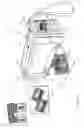


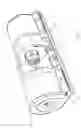
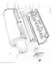
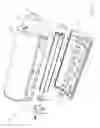
Sources:
- United States Patent and Trademark Office - verify current appl. status at the USPTO↗
Recent applications in this class:
- » 20250162324 2025-05-22
STORAGE BAG AND PRINTING APPARATUS - » 20250162323 2025-05-22
LIQUID DISCHARGE HEAD - » 20250135786 2025-05-01
Ink-Receiving Body And Recording Method - » 20250083445 2025-03-13
FLUID EJECTION DEVICE ASSEMBLIES - » 20250065635 2025-02-27
LIQUID EJECTING APPARATUS - » 20250050646 2025-02-13
INK JET RECORDING METHOD AND INK JET RECORDING APPARATUS - » 20250050645 2025-02-13
INK CONTAINER AND RECORDING APPARATUS - » 20250050644 2025-02-13
APPARATUS FOR STORING AND/OR SUPPLYING INK TO AN INKJET PRINTHEAD - » 20250018722 2025-01-16
INK CARTRIDGE - » 20250018721 2025-01-16
INK CARTRIDGE AND INKJET RECORDING DEVICE INCLUDING INK CARTRIDGE