WALL-MOUNTED Z RAIL WITH QUICK ATTACH ACCESSORIES
US20100025552A1
2010-02-04
12/512,936
2009-07-30
Abstract:
A system and method for hanging an object on a supporting structure, the system comprising: a rail for affixing to a supporting structure, the rail comprising a vertical bend extending outward from the supporting structure and forming a projection; and a bracket accessory slidably mounted in a z-direction on the rail, wherein the bracket accessory has a hook for slidably engaging the projection on the rail, the bracket accessory moveable in the z-direction along the rail, or a positive y-direction up from the rail only.
Interested in similar patents?
Get notified when new applications in this technology area are published.
Classification:
A47B96/067 » CPC main
Details of cabinets, racks or shelf units not covered by a single one of groups - ; General details of furniture; Brackets or similar supporting means for cabinets, racks or shelves Horizontal rails as suspension means in a cantilever arrangement
A47B96/06 IPC
Details of cabinets, racks or shelf units not covered by a single one of groups - ; General details of furniture Brackets or similar supporting means for cabinets, racks or shelves
Description
CROSS-REFERENCES TO RELATED APPLICATIONS
This application claims the benefit of U.S. Provisional Application No. 61/137,376, filed on Jul. 30, 2008, which is incorporated herein by reference in its entirety and for all purposes.
BACKGROUND OF THE INVENTION
1. Field of the Invention
This invention relates to modular storage systems, wall-mounted rails and more specifically to a wall-mounted Z rail and removably attached bracket accessories for consumer and other applications.
2. Background
U.S. Pat. No. 5,222,611 to Wood et al. discloses a wall-unit hanging system for hanging shelves and cabinets on a wall. A vertical panel includes a cut-out portion designed to receive a mounting rail. The cut-out portion of the vertical panel includes dimensions substantially similar to the width and depth of the mounting rail. The mounting rail is defined by a projection designed to extend outward and upward from the wall and is formed by removing a portion of the mounting rail, which leaves a groove between the wall and the projection. A bracket is shaped to secure the vertical panel to the mounting rail and the bracket is affixed to the vertical bracket with screws or bolts.
U.S. Pat. No. 3,117,353 to Edwards discloses a clip system for hanging wood paneling on a wall. A panel element is secured to a base element by a plurality of hooks, the hooks being arranged in pairs so that a hook on the panel element engages with a hook on the base element. Each hook has a wide attaching flange provided with holes to receive screws by means of which the hook is secured either to the panel element or to the base element. A short inclined portion extends away from the wide attaching flange and to a carrying arm on each hook. The carrying arms on each hook allow the hook on the panel element to engage with the hook on the base element.
SUMMARY OF THE PRESENT INVENTION
A system and method for hanging an object on a supporting structure is presented. This system provides a rail affixed to a supporting structure for mounting accessories having hook brackets (“bracket accessories.”) Bracket accessories may include a shelf, a hook, a bin, a tray, a kitchen accessory, a vase, a toothbrush holder and a soap dish. The bracket accessories are slidably mounted on the rail in a z-direction, wherein the bracket accessories have a hook for slidably engaging a projection on the rail, the bracket accessory moveable in a z-direction along the rail, and a positive y-direction up from the rail while being substantially constrained from movement in an x-direction toward and away from the rail, and in a negative y-direction down from the rail.
The method for hanging an object on a supporting structure comprises the steps of: 1) attaching a rail to a support structure, the rail comprising a vertical bend extended outward from the supporting structure, forming a projection, and 2) engaging a bracket accessory to the rail by slidably mounting the bracket accessory on the rail in a z-direction, wherein the bracket accessory has a hook for slidably engaging the projection on the rail, the bracket accessory moveable in a z-direction along the rail, and a positive y-direction up from the rail while being substantially constrained from movement in an x-direction toward and away from the rail, and in a negative y-direction down from the rail.
BRIEF DESCRIPTION OF DRAWINGS
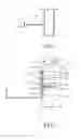
FIG. 1 is a fragmented side section view of a wall anchor, Z bend rail, screw and bracket accessory according to an embodiment of the present invention.
FIG. 2 is an assembled view of FIG. 1 including a x-axis, y-axis, z-axis, rotation moment about the x-axis, rotational moment about the y-axis, and rotational moment about the z-axis.
FIGS. 3A and 3B are side views of the bracket accessory of FIG. 1 according to an embodiment of the present invention.
FIGS. 4A and 4B are side views of the Z bend rail of FIG. 1 according to an embodiment of the present invention.
FIG. 5 is a perspective view showing the wall-mounted Z rail with quick attach accessories according to an embodiment of the present invention.
DETAILED DESCRIPTION OF THE PREFERRED EMBODIMENTS
There is a need for wall-mounted z rails with quick attach accessories, which allow accessories to be removed and re-organized easily and quickly, the accessories to be securely mounted in place while being slidable along a rail and accessories to be re-located to another position on a wall without re-mounting hanging hardware.
In accordance with some embodiments, a system for quickly hanging accessories on a wall, without installing hardware is provided.
In accordance with some variations, a system for hanging bracket accessories at any location along a rail is provided.
In accordance with some variations, bracket accessories are securely attached to a rail.
In accordance with some variations, a system for allowing bracket accessories to slide along a rail and to be easily adjusted by sliding for re-organization purposes is provided.
Referring now to FIG. 1, shown is a Z bend rail 10, a wall anchor 12, a screw 14 and a bracket accessory 16.
The Z bend rail 10 is attached to a supporting structure, or a wall by a wall anchor 12 and a screw 14.
In operation, the bracket accessory 16 slide mounts onto the Z bend rail 10, allowing movement in a Z-direction along the Z bend rail.
Referring to FIG. 2, shown is an assembled Z bend rail 10, a wall anchor 12, a screw 14 and a bracket accessory 16, including an x-axis 18, a y-axis 19, a z-axis 20, a rotational moment about the x-axis 21, a rotational moment about the y-axis 22, and a rotational moment about the z-axis 23.
The width of the Z bend rail 10 includes a mounting section 24, a vertical bend 25, and a rail projection 26. The Z bend rail 10 may vary in length. In preferred embodiments, the length of the Z bend rail 10 is four feet eleven and three-fourths inches to one foot and eleven and three-fourths inches. The Z bend rail 10 has an attaching means allowing the Z bend rail 10 to be affixed to a supporting structure through a plurality of holes 28, preferably three-sixth inches to one-eighth inch holes; however, a variety of holes of different shapes and dimensions may be used. The bracket accessory 16 has a hook to engage the rail projection 26 of the Z bend rail 10. The wall anchor 12 and screw 14 may be inserted into the plurality of holes 28 for affixing to the support structure 27. Various metals, including twelve to twenty-six gauge thickness steel, such as stainless steel, may be used for construction of the Z bend rail 10 and bracket accessory 16. In preferred embodiments stainless steel, e.g., sixteen to twenty gauge thickness stainless steel is used for construction of the Z bend rail 10 and the bracket accessory 16.
In operation, when the bracket accessory 16 is mounted to the Z bend rail 10 at the rail projection 26 by placing the bracket accessory 16 on the Z bend rail, the weight of the bracket accessory 16 will transfer the load from the rail projection 26, along the vertical bend 25, to the mounting section 24, such that gravity substantially constrains movement of the bracket accessory 16 in the negative y-direction. The bracket accessory 16 is slidable along the Z bend rail 10 along the z-axis 20. The bracket accessory 16 engages the Z bend rail 10 at the rail projection 26 to allow movement in the Z-direction along the Z bend rail, or a positive Y-direction up from the Z bend rail only. Rotational movement of the bracket accessory 16 about the x-axis 18, y-axis 19 and z-axis 20 of the Z bend rail 10 is prevented by engagement of the bracket accessory 16 at the Z bend rail 10.
Referring to FIGS. 3A and 3B, shown is a bracket accessory 16. The bracket accessory 16 has a hook 30.
The hook 30 has a hook width 32, a hook length 34, and hook bends 36 and 38. The hook width 32 is the inner width of the hook, and does not include the thickness of the hook itself. The hook width 32 of the hook 30 is equal to at least the thickness of the metal used for construction of the Z bend rail 10. The greater the thickness of the metal used for construction of the Z bend rail 10, the greater the required hook width 32 so that the bracket accessory 16 engages the Z bend rail to allow movement in the Z-direction along the Z bend rail 10, or a positive Y-direction up from the Z bend rail only. Various metals, including twelve to twenty-six gauge thickness steel, such as stainless steel, may be used for construction of the Z bend rail 10 and bracket accessory 16. In preferred embodiments stainless steel, e.g., sixteen to twenty gauge thickness stainless steel is used for construction of the Z bend rail 10 and the bracket accessory 16. A hook width 32 of one quarter inch is preferred for a Z bend rail 10 using sixteen to twenty gauge thickness steel. A hook length 34 may be various lengths and is dependent on the Z bend rail projection 26. A hook length 34 of five-eighths inches is preferred and corresponds with the length of the rail projection 24. Various hook lengths 34 may be used. Hook bends 36 and 38 bend at ninety degrees, each creating a radius dependent on the thickness of the metal used for construction of the Z bend rail 10. Radii at hook bends 36 and 38 are preferably one-sixteenth to one-eighth inches for sixteen to twenty gauge thickness steel.
In operation, the hook 30 of the bracket accessory 16 slidably engages the Z bend rail projection 24.
Referring to FIGS. 4A and 4B, shown is a side view of a Z bend rail 10.
The Z bend rail 10 includes a mounting section 20, a vertical bend 22 and a rail projection 24. The vertical bend 22 has angles 40 and 42.
Angles 40 and 42 are obtuse angles. Preferably, angles 40 and 42 are equal and are one-hundred fifty three to one-hundred and sixty-three degrees for a bracket accessory hook 30 made of sixteen to twenty gauge thickness steel; however angles 40 and 42 may measure various degrees depending on the type and thickness of metal used. Angles may be increased to mount a bracket accessory 16 farther away from a support structure 27. The mounting section 24, vertical bend 25 and rail projection 26 may be various lengths. The mounting section 24 preferably measures seven-eighths an inch to thirty-six inches in length. The mounting section 24 may be extended in length in some embodiments to support an additional load. The vertical bend 25 preferably measures one quarter inch in length. The rail projection 26 preferably measures one-half inch to one and one-half inches in length.
In operation, the vertical bend 25 creates a distance between the mounting section 24 of the Z bend rail 10 such that the hook 30 of the bracket accessory may engage the Z bend rail 10 at the rail projection 26.
Referring to FIG. 5, shown is a plurality of bracket accessories 16 mounted on a Z bend rail 10. Bracket accessories 16 include a soap dish 50, a hook attachment 52, and a tray 54. The Z bend rail 10 may vary in length. In preferred embodiments, the length of the Z bend rail 10 is four feet eleven and three-fourths inches to one foot and eleven and three-fourths inches. In preferred embodiments, the length of the bracket accessories 16 is two to forty-eight inches; however, various lengths may be used.
In operation, the bracket accessories 16 are interchangeable and easily removed.
Referring to FIG. 5, shown is a soap dish 50. The soap dish 50 has a hook 56 and a tray 58.
The tray 58 has a diameter of five and one-half inches; however, various diameters may be used. The tray may be curved, or uncurved, and may have various radii of curvature. The hook 56 has a length of five-eights inches; however, various lengths may be used. The soap dish 50 may be formed from one piece of metal. Dimensions of the hook 56 correspond to dimensions, for a given metal, of the Z bend rail 10 such that the soap dish 50 is securely held into place on the Z bend rail 10, and is slidable.
In operation, the soap dish 50 slidably engages the Z bend rail 10. The soap dish 50 engages the Z bend rail 10 to allow movement in the z-direction along the Z bend rail 10, or a positive y-direction up from the Z bend rail 10 only. Rotational movement of the soap dish 50 about the x-axis, y-axis and z-axis of the Z bend rail 10 is prevented by engagement of the hook 56 at the Z bend rail 10.
Referring to FIG. 5, shown is a hook attachment 52. The hook attachment 52 has a hook 60 and a holding member 62.
The holding member 62 has a vertical length of two and one-half inches; however various lengths may be used. The holding member 62 has a diameter of two and one-fourth inches; however, various diameters may be used. The holding member 62 may have various radii of curvature. The hook attachment 52 may be formed from one piece of metal. Dimensions of the hook 60 correspond to dimensions, for a given metal, of the Z bend rail 10 such that the hook attachment 52 is securely held into place on the Z bend rail 10, and is slidable.
In operation, the hook attachment 52 slidably engages the Z bend rail 10. The hook attachment 52 engages the Z bend rail 10 to allow movement in the z-direction along the Z bend rail 10, or a positive y-direction up from the Z bend rail 10 only. Rotational movement of the hook attachment 52 along the x-axis, y-axis and z-axis of the Z bend rail 10 is prevented by engagement of the hook 60 at the Z bend rail 10.
Referring to FIG. 5, shown is a tray 54. The tray 54 has a hook 64 and a shelf 66.
The shelf 66 has a height of two and one-eights inches and a width of three and one-eights inches; however, various heights and widths may be used. The tray 54 may be formed from one piece of metal. Dimensions of the hook 64 correspond to dimensions, for a given metal, of the Z bend rail 10 such that the tray 54 is securely held into place on the Z bend rail 10, and is slidable.
In operation, the tray 54 slidably engages the Z bend rail 10. The tray 54 engages the Z bend rail 10 to allow movement in the z-direction along the Z bend rail 10, or a positive y-direction up from the Z bend rail 10 only. Rotational movement of the tray 54 along the x-axis, y-axis and z-axis of the Z bend rail 10 is prevented by engagement of the hook 64 at the Z bend rail 10.
It should be understood that shelves, hooks, bins, trays, vases, toothbrush holders and soap dishes do not limit the present invention, but only illustrate some of the various bracket accessories attached to a z bend rail covered by this invention. While the invention has been described in detail with reference to preferred embodiments, it is understood that variations and modifications thereof may be made without departing from the true spirit and scope of the invention.
Claims
What is claimed is:1. A hanging system for hanging an object on a supporting structure, the system comprising:
a rail for affixing to a supporting structure, the rail comprising a vertical bend extending outward from the supporting structure and forming a projection; and
a bracket accessory slidably mounted in a z-direction on the rail, wherein the bracket accessory has a hook for slidably engaging the projection on the rail, the bracket accessory moveable in the z-direction along the rail, or a positive y-direction up from the rail only.
2. The hanging system of claim 1, wherein the bracket accessory comprises at least one of: a shelf, a hook, a bin, a tray, a kitchen accessory, a vase, a toothbrush holder and a soap dish.
3. The hanging system of claim 1, wherein the rail has an attaching means allowing the rail to be affixed to the supporting structure at a desired location.
4. The hanging system of claim 1, wherein the bracket accessory is securely attached to the rail to prevent rotation along the x-axis, y-axis and z-axis.
5. The hanging system of claim 1, wherein the bracket accessory is slidable along the rail in the z-direction.
6. The hanging system of claim 1, wherein the bracket accessory is formed from one piece of metal.
7. A method for hanging an object on a supporting structure, the method comprising:
attaching a rail to a support structure, the rail comprising a vertical bend extending outward from the supporting structure, forming a projection; and
engaging a bracket accessory to the rail by slidably mounting the bracket accessory on the rail in a z-direction, wherein the bracket accessory has a hook for slidably engaging the projection on the rail, the bracket accessory moveable in the z-direction along the rail, or a positive y-direction up from the rail only.
8. The method for hanging an object of claim 7, wherein the bracket accessory comprises at least one of: a shelf, a hook, a bin, a tray, a kitchen accessory, a vase, a toothbrush holder and a soap dish.
9. The method for hanging an object of claim 7, wherein the rail has an attaching means allowing the rail to be affixed to the supporting structure at a desired location.
10. The method for hanging an object of claim 7, wherein the bracket accessory is securely attached to the rail to prevent rotation along the x-axis, y-axis and z-axis.
11. The method for hanging an object of claim 7, wherein the bracket accessory is slidable along the rail in the z-direction.
12. The method for hanging an object of claim 7, wherein the bracket accessory is formed from one piece of metal.
Images & Drawings included:


Sources:
- United States Patent and Trademark Office - verify current appl. status at the USPTO↗
Recent applications in this class:
- » 20240335037 2024-10-10
OBJECT HANGING SYSTEM AND METHOD - » 20230371690 2023-11-23
Floating shelf system - » 20230320486 2023-10-12
Floating shelf brackets and methods of using same - » 20230147682 2023-05-11
Attachment interface, automated storage system, and gripper - » 20220338631 2022-10-27
RAIL SYSTEM FOR WALL OR STRUCTURE - » 20220273099 2022-09-01
Shelf holding structure having attachable and detachable power supply - » 20220225769 2022-07-21
Object hanging system and method - » 20210401175 2021-12-30
Floating shelf brackets and methods of using same - » 20210204693 2021-07-08
SUPPORT BRACKET FOR COUNTERTOPS AND SHELVING - » 20200146450 2020-05-14
Floating shelf brackets and methods of using same