Cutting tool
US20100037532A1
2010-02-18
12/521,282
2006-12-26
✅ Patent granted
US 8,092,561 B2
2012-01-10
WO; PCT/KR2006/005707; 20061226
WO; WO2008/078845; 20080703
Anthony Green | Pegah Parvini
2027-10-16
Abstract:
A cutting tool including a fine and uniform alumina-based substrate is disclosed herein. In an exemplary embodiment, the alumina-based substrate includes 0.1 to 25% by volume of one or more metal oxides, or 5 to 80% by volume of metal carbonitride and 0.01 to 10% by volume of one or more metal oxides. Metal constituting the metal oxide and the metal carbonitride is selected from the group consisting of elements from Groups III to VI (including La group and Ac group) of the periodic table, Mg and Co. The metal oxides added to alumina reside at the boundaries of alumina grains, thereby prohibiting the alumina grains from growing excessively during a sintering process.
Inventors:
- Kwon Hee Park 1 🇰🇷 Daegu, South Korea
- Sung Su Chun 3 🇰🇷 Daegu, South Korea
- Sang Woong Na 1 🇰🇷 Daegu, South Korea
Assignee:
- TaeguTec, Ltd. 27 🇰🇷 Daegu, South Korea
Interested in similar patents?
Get notified when new applications in this technology area are published.
Classification:
B23B27/146 » CPC main
Tools for turning or boring machines ; Tools of a similar kind in general; Accessories therefor; Cutting tools of which the bits or tips or cutting inserts are of special material; Specially shaped plate-like cutting inserts, i.e. length greater or equal to width, width greater than or equal to thickness characterised by having a special shape Means to improve the adhesion between the substrate and the coating
C04B41/87 » CPC further
After-treatment of mortars, concrete, artificial stone or ceramics; Treatment of natural stone of only ceramics; Coating or impregnation with inorganic materials Ceramics
C04B41/89 » CPC further
After-treatment of mortars, concrete, artificial stone or ceramics; Treatment of natural stone of only ceramics; Coating or impregnation for obtaining at least two superposed coatings having different compositions
B23B2224/04 » CPC further
Materials of tools or workpieces composed of a compound including a metal Aluminium oxide
B23B2224/08 » CPC further
Materials of tools or workpieces composed of a compound including a metal Aluminium nitride
B23B2224/12 » CPC further
Materials of tools or workpieces composed of a compound including a metal Chromium carbide
B23B2224/24 » CPC further
Materials of tools or workpieces composed of a compound including a metal Titanium aluminium nitride
B23B2224/28 » CPC further
Materials of tools or workpieces composed of a compound including a metal Titanium carbide
B23B2224/32 » CPC further
Materials of tools or workpieces composed of a compound including a metal Titanium carbide nitride (TiCN)
B23B2224/36 » CPC further
Materials of tools or workpieces composed of a compound including a metal Titanium nitride
B23B2228/08 » CPC further
Properties of materials of tools or workpieces, materials of tools or workpieces applied in a specific manner applied by physical vapour deposition [PVD]
B23B2228/105 » CPC further
Properties of materials of tools or workpieces, materials of tools or workpieces applied in a specific manner; Coatings with specified thickness
B23B2228/61 » CPC further
Properties of materials of tools or workpieces, materials of tools or workpieces applied in a specific manner Materials comprising whiskers
C04B2235/3206 » CPC further
Aspects relating to ceramic starting mixtures or sintered ceramic products; Composition of constituents of the starting material or of secondary phases of the final product; Constituents and secondary phases not being of a fibrous nature; Metal oxides, mixed metal oxides, or oxide-forming salts thereof, e.g. carbonates, nitrates, (oxy)hydroxides, chlorides; Alkaline earth oxides or oxide forming salts thereof, e.g. beryllium oxide Magnesium oxides or oxide-forming salts thereof
C04B2235/3225 » CPC further
Aspects relating to ceramic starting mixtures or sintered ceramic products; Composition of constituents of the starting material or of secondary phases of the final product; Constituents and secondary phases not being of a fibrous nature; Metal oxides, mixed metal oxides, or oxide-forming salts thereof, e.g. carbonates, nitrates, (oxy)hydroxides, chlorides; Rare earth oxide or oxide forming salts thereof, e.g. scandium oxide Yttrium oxide or oxide-forming salts thereof
C04B2235/3856 » CPC further
Aspects relating to ceramic starting mixtures or sintered ceramic products; Composition of constituents of the starting material or of secondary phases of the final product; Constituents and secondary phases not being of a fibrous nature; Non-oxide ceramic constituents or additives; Nitrides, e.g. oxynitrides, carbonitrides, oxycarbonitrides, lithium nitride, magnesium nitride Carbonitrides, e.g. titanium carbonitride, zirconium carbonitride
C04B2235/3886 » CPC further
Aspects relating to ceramic starting mixtures or sintered ceramic products; Composition of constituents of the starting material or of secondary phases of the final product; Constituents and secondary phases not being of a fibrous nature; Non-oxide ceramic constituents or additives; Nitrides, e.g. oxynitrides, carbonitrides, oxycarbonitrides, lithium nitride, magnesium nitride Refractory metal nitrides, e.g. vanadium nitride, tungsten nitride
Y10T407/27 » CPC further
Cutters, for shaping comprising tool of specific chemical composition
C04B41/009 » CPC further
After-treatment of mortars, concrete, artificial stone or ceramics; Treatment of natural stone characterised by the material treated
C04B35/119 » CPC further
Shaped ceramic products characterised by their composition ; Ceramics compositions ; Processing powders of inorganic compounds preparatory to the manufacturing of ceramic products based on oxide ceramics based on aluminium oxide; Fine ceramics; Composites with zirconium oxide
B23B27/14 IPC
Tools for turning or boring machines ; Tools of a similar kind in general; Accessories therefor Cutting tools of which the bits or tips or cutting inserts are of special material
C04B41/5062 » CPC further
After-treatment of mortars, concrete, artificial stone or ceramics; Treatment of natural stone; Coating or impregnating e.g. injection in masonry, partial coating of green or fired ceramics, organic coating compositions for adhering together two concrete elements, with inorganic materials non-oxide ceramics Borides, Nitrides or Silicides
C04B41/5063 » CPC further
After-treatment of mortars, concrete, artificial stone or ceramics; Treatment of natural stone; Coating or impregnating e.g. injection in masonry, partial coating of green or fired ceramics, organic coating compositions for adhering together two concrete elements, with inorganic materials non-oxide ceramics; Borides, Nitrides or Silicides Aluminium nitride
C04B41/52 » CPC further
After-treatment of mortars, concrete, artificial stone or ceramics; Treatment of natural stone; Coating or impregnating e.g. injection in masonry, partial coating of green or fired ceramics, organic coating compositions for adhering together two concrete elements, Multiple coating or impregnating multiple coating or impregnating with the same composition or with compositions only differing in the concentration of the constituents, is classified as single coating or impregnation
C04B41/4529 » CPC further
After-treatment of mortars, concrete, artificial stone or ceramics; Treatment of natural stone; Coating or impregnating e.g. injection in masonry, partial coating of green or fired ceramics, organic coating compositions for adhering together two concrete elements, characterised by the method of application applied from the gas phase
C04B41/5068 » CPC further
After-treatment of mortars, concrete, artificial stone or ceramics; Treatment of natural stone; Coating or impregnating e.g. injection in masonry, partial coating of green or fired ceramics, organic coating compositions for adhering together two concrete elements, with inorganic materials non-oxide ceramics; Borides, Nitrides or Silicides Titanium nitride
C04B35/117 » CPC further
Shaped ceramic products characterised by their composition ; Ceramics compositions ; Processing powders of inorganic compounds preparatory to the manufacturing of ceramic products based on oxide ceramics based on aluminium oxide; Fine ceramics Composites
B24B1/00 IPC
Processes of grinding or polishing; Use of auxiliary equipment in connection with such processes
B32B9/00 IPC
Layered products characterised by particular substances used
B32B9/00 IPC
Layered products comprising a layer of a particular substance not covered by groups -
B32B19/00 IPC
Layered products comprising a layer of natural mineral fibres or particles, e.g. asbestos, mica
B23P15/28 IPC
Making specific metal objects by operations not covered by a single other subclass or a group in this subclass cutting tools
B26D1/00 IPC
Cutting through work characterised by the nature or movement of the cutting member or particular materials not otherwise provided for ; Apparatus or machines therefor; Cutting members therefor
B26D3/00 IPC
Cutting work characterised by the nature of the cut made; Apparatus therefor
B24D11/00 IPC
Constructional features of flexible abrasive materials; Special features in the manufacture of such materials
Description
TECHNICAL FIELD
The present invention generally relates to an alumina-based ceramic cutting tool, and more particularly to an alumina-based ceramic cutting tool with coating layers formed on its surface.
BACKGROUND ART
Alumina is widely used as a material for substrates of cutting tools due to its excellent mechanical properties and thermal resistance. A TiN coating layer is formed on the surface of an alumina cutting tool to improve surface roughness, reduce cutting resistance and prevent adhesion of workpiece on the cutting tool. However, the TiN coating layer has a low hardness and thus may be easily worn out due to the friction occurring during a cutting operation. When cutting hard materials such as a cast iron, the TiN coating layer tends to wear out more easily. Further, the TiN coating layer is easily oxidized at above 1000° C. under an atmospheric exposure. Thus, when the cutting tool performs a high-speed cutting, the TiN coating layer, which is subjected to a high temperature, tends to be easily oxidized and peeled off from the substrate.
The removal of the TiN coating layer causes the cutting edges to wear out rapidly. Further, it causes an increase in cutting resistance, thereby accelerating the abrasion of the cutting tool. This shortens the service life of the cutting tool.
DISCLOSURE
Technical Problem
It is an object of the present invention to provide a coated alumina-based ceramic cutting tool having an improved wear resistance.
It is another object of the present invention to provide a coated alumina-based ceramic cutting tool having an improved mechanical performance under high-speed cutting.
It is yet another object of the present invention to provide a coated alumina-based ceramic cutting tool having an enhanced tool life.
Technical Solution
In order to achieve the above objects and other objects, the cutting tool according to the present invention comprises an alumina-based substrate. Preferably, the substrate includes 0.1 to 25% by volume of one or more metal oxides, or 5 to 80% by volume of metal carbonitride and 0.01 to 10% by volume of one or more metal oxides. Metal comprising said metal oxide and said metal carbonitride is selected from a group consisting of elements of Groups III to VI (including La group and Ac group) in the periodic table of elements, Mg and Co. Said metal oxides added to alumina reside at the boundaries of alumina grains, thereby prohibiting the alumina grains from growing excessively during a sintering process. As a result, a fine and uniform alumina-based substrate may be obtained.
Further, when 5 to 80% by volume of metal carbonitride is added to alumina, fine alumina grains and uniform microstructure may be obtained with the same principle. Moreover, metal carbonitride provides a much increased toughness than metal oxides, thereby expanding the applications of the alumina-based ceramic cutting tool including the high-speed cutting of high-hardness steels.
Also, one or more Al—Ti—Cr based nitride coating layers are formed on the substrate of the cutting tool. The one or more Al—Ti—Cr based nitride coating layers are formed on the substrate of the cutting tool with a thickness of 0.3 to 5.0 μm, preferably 0.5 to 2.0 μm. The composition of said Al—Ti—Cr based nitride coating layer may be AlWTiXCrYSiXCVN1-V (W+X+Y+Z=1, V=0˜1).
Moreover, the coating layer may be formed by a physical vapor deposition (PVD) method.
DESCRIPTION OF DRAWINGS
FIG. 1 is a photograph showing various types of cutting inserts where the present invention may be applied.
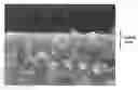
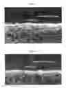
FIG. 2 is an electron microscopic photograph showing a cross-section of a cutting tool in accordance with a first embodiment of the present invention.
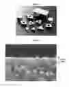
FIG. 3 is an electron microscopic photograph showing a cross-section of a conventional cutting tool.
FIG. 4 is an optical microscopic photograph of the cutting tool of FIG. 2 after a Vickers hardness test is conducted to compare adhesion strength of the coating layer to the substrate.
FIG. 5 is an optical microscopic photograph of the cutting tool of FIG. 3 after a Vickers hardness test is conducted to compare adhesion strength of the coating layer to the substrate.
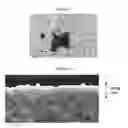
FIG. 6 is an electron microscopic photograph showing a cross-section of a cutting tool in accordance with a second embodiment of the present invention.
FIGS. 7 and 8 are electron microscopic photographs showing cross-sections of conventional cutting tools.
FIG. 9 is an optical microscopic photograph of the cutting tools of FIG. 6 after a Vickers hardness test is conducted to compare adhesion strength of the coating layer to the substrate.
FIG. 10 is an optical microscopic photograph of the cutting tool of FIG. 7 after a Vickers hardness test is conducted to compare adhesion strength of the coating layer to the substrate.
FIG. 11 is an optical microscopic photograph of the cutting tools of FIG. 8 after a Vickers hardness test is conducted to compare adhesion strength of the coating layer to the substrate.
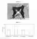
FIG. 12 is a graph comparing tool lives of the cutting tool in accordance with the first embodiment of the present invention and conventional cutting tools.
FIG. 13 is an optical microscopic photograph of the cutting tool in accordance with the first embodiment of the present invention, showing wear extent of a cutting edge after use.
FIGS. 14 to 16 are optical microscopic photographs of conventional cutting tools, showing their respective wear extents of cutting edges after use.
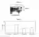
FIG. 17 is a graph comparing tool lives of the cutting tool in accordance with the second embodiment of the present invention and conventional cutting tools.
FIG. 18 is an optical microscopic photograph of the cutting tool in accordance with the second embodiment of the present invention, showing wear extent of a cutting edge after use.
FIGS. 19 to 21 are optical microscopic photographs of conventional cutting tools, showing their respective wear extents of cutting edges after use.
BEST MODE FOR CARRYING OUT THE INVENTION
According to a first embodiment of the present invention, an alumina-based ceramic cutting insert comprises alumina and 0.1 to 25% by volume of one or more metal oxides. Metal composing said metal oxide is selected from a group consisting of elements of Groups III to VI (including La group and Ac group) in the periodic table of elements, Mg and Co. The cutting insert has one or more Al—Ti—Cr based nitride coating layers formed on the surface. Preferably, the one or more Al—Ti—Cr based nitride coating layer have a thickness of 0.3 to 5.0 μm, preferably 0.5 to 2.0 μm. When the thickness of the coating layer is less than 0.3 μm, the coating layer is easily worn out and peeled off during a cutting process. Thus, the effect of the coating layer of enhancing tool life is not provided. Further, when the coating layer is thicker than 0.5 μm, the adhesion strength between the substrate and the coating material becomes weak, and the coating layer is easily peeled off or damaged. This shortens the tool life.
FIG. 1 is a photograph showing various types of cutting inserts, to which the present invention may be applied. While the present invention is described with reference to embodiments of cutting tools, it is appreciated that the present invention may also be applied to various mechanical structures or functional parts which are made from ceramic.
FIGS. 2 and 3 are photographs of cross-sections of said cutting insert and a conventional cutting insert, respectively, taken by an electron microscope at a magnification of 7000 to compare the adhesion strengths of coating layers to substrates. FIG. 2 shows a cross-section of a cutting insert in accordance with the present invention, wherein a coating layer having a composition of (TiAlCrN+TiN) is PVD coated with a thickness of about 1.2 μm on an alumina-based substrate having a composition of (Al2O3+8.0% ZrO2+0.3% MgO). FIG. 3 shows a cross-section of a conventional cutting insert, wherein a coating layer having a composition of TiN is PVD coated with a thickness of about 1.0 μm on an alumina-based substrate having a composition of (Al2O3+3.0% ZrO2+0.3% MgO).
As can be seen through comparing FIGS. 2 and 3, the cutting insert of FIG. 2 has the coating layer closely adhered to the substrate without any gap, whereas the cutting insert of FIG. 3 shows a number of irregular gaps existing between the coating layer and the substrate (as indicated by arrows).
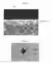
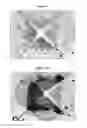
FIG. 4 is a photograph for comparing the adhesion strength of the coating layer to the substrate, taken by an optical microscope at a magnification of 200. FIG. 4 shows a surface of the cutting insert according to the first embodiment of the present invention after it is subjected to a Vickers hardness test. FIG. 5 is a photograph taken by an optical microscope at a magnification of 200 and shows a surface of a conventional cutting insert after it is subjected to the same Vickers hardness test. A diamond pyramid (indenter) having an angle of 136° between the two faces was used in the Vickers hardness test.
By comparing FIGS. 4 and 5, it is confirmed that the coating layer of the cutting tool of FIG. 4 is not peeled off from the substrate and a pyramid-shaped indentation similar to the shape of the indenter is formed on its surface. The coating layer of the cutting tool of FIG. 5 is heavily peeled off from the substrate due to the pressure of the indenter. Such removal of the coating layer occurs due to the weak adhesion strength between the coating layer and the substrate.
According to a second embodiment of the present invention, an alumina-based ceramic cutting insert comprises alumina, 5 to 80% by volume of metal carbonitride, and 0.1 to 10% by volume of one or more metal oxides. Metal composing said metal carbonitride and said metal oxide is selected from a group consisting of elements of Groups III to VI (including La group and Ac group) in the periodic table of elements, Mg and Co. The cutting insert has one or more Al—Ti—Cr based nitride coating layers formed on the surface. Preferably, the one or more Al—Ti—Cr based nitride coating layer have a thickness of 0.3 to 5.0 μm, preferably 0.5 to 2.0 μm.
FIGS. 6 to 8 are photographs taken by an electron microscope at a magnification of 7000 for comparing the adhesion strengths of the coating layers to the substrates, which show cross-sections of said cutting insert and a conventional cutting insert, respectively. FIG. 6 shows a cross-section of a cutting insert constructed in accordance with the second embodiment of the present invention, wherein a coating layer having a composition of TiAlCrN is PVD coated with a thickness of about 1.2 μm on an alumina-based substrate having a composition of (Al2O3+35% TiCN+0.5% MgO+1.0% Y2O3). FIG. 7 shows a cross-section of one of the conventional cutting inserts, wherein a coating layer having a composition of TiN is PVD coated with a thickness of about 0.2 μm on an alumina-based substrate having a composition of (Al2O3+26% TiCN+0.5% MgO). FIG. 8 shows a cross-section of another conventional cutting insert, wherein a coating layer having a composition of TiN is PVD coated with a thickness of 0.2 μm on an alumina-based substrate having a composition of (Al2O3+30% TiCN+0.3% MgO).
As can be seen by comparing FIGS. 6 to 8, the cutting insert of FIG. 6 has the coating layer closely adhered to the substrate without any gap, whereas the coating layers of the cutting tools of FIGS. 7 and 8 are peeled off from several places of the surfaces (as indicated by arrows).
FIG. 9 is a photograph for comparing the adhesion strength of the coating layer to the substrate, which was taken by an optical microscope at a magnification of 200. FIG. 9 shows a surface of the cutting insert according to the second embodiment of the present invention after it is subjected to a Vickers hardness test. FIGS. 10 and 11 are photographs taken through an optical microscope at a magnification of 200, which show the surfaces of the cutting inserts shown in FIGS. 7 and 8, respectively, after they are subjected to the Vickers hardness test.
By comparing FIGS. 9 to 11, it is confirmed that the coating layer of the cutting tool of FIG. 9 is not peeled off from the substrate and a pyramid-shaped indentation similar to the shape of the indenter is formed on its surface. The coating layers of the cutting tools of FIGS. 10 and 11 are heavily peeled off from the substrates of the cutting tools around the indenter.
The test examples of the cutting inserts, which are constructed in accordance with the present invention, are described below.
Test Example 1
A cutting performance test of the cutting insert, which is constructed in accordance with the present invention, was conducted as described below.
The tool life of each cutting insert was measured, wherein the tool life is the time spent for a wear amount of a flank face of the cutting tool to reach 0.25 mm.
In said cutting performance test, the following is used: a cutting insert A comprising a substrate having a composition of (Al2O3+8.0% ZrO2+0.3% MgO) without any coating layer formed thereon; a cutting insert B comprising a first TiAlCrN coating layer and a second TiN coating layer on a substrate having the same composition as that of the cutting insert A; a cutting insert C comprising a TiN coating layer on a substrate having a composition of (Al2O3+3.0% ZrO2+0.3% MgO); and a cutting insert D comprising a substrate having a composition of (Al2O3+10.0% ZrO2+0.5% MgO) without any coating layer formed thereon. The cutting inserts are SNGN120412 turning inserts according to the ISO standards. The cutting insert B is in accordance with the present invention, whereas the cutting inserts C and D are conventional.
The cutting conditions were as follows: cutting speed (v)=600 rpm; feed rate (f)=0.3 mm/rev; and depth of cut (d)=2 mm. Furthermore, each cutting insert was tested to cut a gray cast iron rod having a diameter of 150 mm and a length of 700 mm. Test results are shown in [Table 1] below and FIG. 12.
| TABLE 1 | ||
| Coating Layer | ||
| (Thickness μm) | Cutting Result |
| Cutting | First | Second | Tool Life | ||
| Insert | Substrate | Layer | Layer | (min) | Remarks |
| A | Al2O3 + 8% ZrO2 + 0.3% MgO | — | — | 15 | |
| B | Al2O3 + 8% ZrO2 + 0.3% MgO | TiAlCrN | TiN | 26 | small |
| (1.0) | (0.2) | amount of | |||
| notch wear | |||||
| C | Al2O3 + 3.0% ZrO2 + 0.3% MgO | TiN | — | 14 | |
| (1.2) | |||||
| D | Al2O3 + 10.0% ZrO2 + 0.5% MgO | — | — | 12 | |
| Insert Type: SNGN120412 | |||||
| Work Material: Gray Cast Iron (HB190-200) | |||||
| Cutting Condition: v = 600 rpm, f = 0.3 mm/rev, d = 2 mm, dry |
As can be seen from Table 1, the tool life of the coated cutting insert B according to the present invention was about twice longer than that of the uncoated cutting insert A having the same substrate. Further, it can be seen that the tool life of the cutting insert B according to the present invention was notably increased over those of conventional cutting inserts C and D. On the other hand, it can be seen that the TiN coating layer of the cutting insert C scarcely contributes to the enhancement of the tool life.
Furthermore, the present inventors proceeded with cutting the cutting inserts A to D for 15 minutes under the same conditions as above [TEST EXAMPLE 1] and measured a flank and a notch wear amounts of the cutting inserts after the cutting. The notch wear amount indicates a wear amount of the deepest worn section. The flank wear amount indicates an average wear amount of worn sections without the notch wear amount.
| TABLE 2 | ||
| Coating Layer | ||
| (Thickness μm) | Cutting Result(mm) |
| Cutting | First | Second | Flank | Notch | |
| Insert | Substrate | Layer | Layer | Wear (Vb) | Wear (Vn) |
| A | Al2O3 + 8% ZrO2 + 0.3% MgO | — | — | 0.25 | 0.50 |
| B | Al2O3 + 8% ZrO2 + 0.3% MgO | TiAlCrN | TiN | 0.13 | 0.29 |
| (1.0) | (0.2) | ||||
| C | Al2O3 + 3.0% ZrO2 + 0.3% MgO | TiN | — | 0.18 | 0.40 |
| (1.2) | |||||
| D | Al2O3 + 10.0% ZrO2 + 0.5% MgO | — | — | 0.27 | 0.75 |
| Insert Type: SNGN120412 | |||||
| Work Material: Gray Cast Iron (HB190-200) | |||||
| Cutting Condition: v = 600 rpm, f = 0.3 mm/rev, d = 2 mm, dry |
According to the cutting result, the cutting insert B according to the present invention has the smallest flank wear amount and notch wear amount.
FIGS. 13 to 16 are photographs taken by an optical microscope at a magnification of 200, which show the worn features of the cutting inserts A to D [Table 2], respectively. It is observed that the wear amount of the cutting insert B is remarkably smaller than those of other cutting inserts A, C and B. This is due to the excellent adhesion strength of the coating layer of the cutting insert B to the substrate, which prohibits the coating layer from easily peeling off from the substrate. The coating layer reduces friction coefficient between the cutting insert and workpiece (even in cast iron cuttings), thereby suppressing the wear of a cutting tool.
Test Example 2
The tool life of each cutting insert was measured, wherein the cutting inserts are: a cutting insert E comprising a substrate having a composition of (Al2O3+1.0% Y2O3+35.0% TiCN+0.5% MgO) without any coating layer formed thereon; a cutting insert F comprising a TiAlCrN coating layer formed on a substrate having the same composition as the cutting insert E; a cutting insert G comprising a TiN coating layer formed on a substrate having a composition of (Al2O3+26.0% TiCN+0.5% MgO); and a cutting insert H comprising a TiN coating layer formed on a substrate having a composition of (Al2O3+30.0% TiCN+0.3% MgO). The cutting inserts are CNGA120408 turning inserts according to the ISO standards. The cutting insert F is in accordance with the present invention, whereas the cutting inserts G and H are conventional. The cutting conditions were: cutting speed (v)=270 rpm; feed rate (f)=0.1 mm/rev; and depth of cut (d)=2 mm. Further, each cutting insert was tested to cut a hardened alloy steel rod having a diameter of 150 mm and a length of 700 mm. The results of such test are shown [Table 3] below and FIG. 17.
| TABLE 3 | |
| Cutting Result |
| Tool | ||||
| Cutting | Coating Layer | Life | ||
| Insert | Substrate | (Thickness μm) | (min) | Remark |
| E | Al2O3 + 1.0% Y2O3 + | — | 20 | — |
| 35.0% TiCN + 0.5% MgO | (—) | |||
| F | Al2O3 + 1.0% Y2O3 + | TiAlCrN (1.2) | 45 | show slow |
| 35.0% TiCN + 0.5% MgO | tool wear | |||
| G | Al2O3 + 26.0% TiCN + | TiN (0.2) | 25 | — |
| 0.5% MgO | ||||
| H | Al2O3 + 30.0% TiCN + | TiN (0.2) | 27 | — |
| 0.3% MgO | ||||
| Insert Type: CNGA120408 | ||||
| Work Material: Hardened Alloy Steel (HRc 45-50) | ||||
| Cutting Condition: v = 270 rpm, f = 0.1 mm/rev, d = 0.5 mm, wet |
As can be seen from above [Table 3], the tool life of the coated cutting insert F according to the present invention was about twice longer than that of the uncoated cutting insert E having the same substrate. Further, it can be seen that the tool life of the cutting insert F according to the present invention was significantly increased over those of conventional cutting inserts G and H.
Furthermore, cutting was performed with the cutting inserts E to H for 15 minutes under the same conditions as above [TEST EXAMPLE 2] and each feature of the cutting inserts was observed. The wear amount of each cutting insert is shown below.
| TABLE 4 | |||
| Wear | |||
| Cutting | Coating Layer | Amount | |
| Insert | Substrate | (Thickness μm) | (mm) |
| E | Al2O3 + 1.0% Y2O3 + 35.0% TiCN + | — | 0.25 |
| 0.5% MgO | (—) | ||
| F | Al2O3 + 1.0% Y2O3 + 35.0% TiCN + | TiAlCrN (1.2) | 0.13 |
| 0.5% MgO | |||
| G | Al2O3 + 26.0% TiCN + 0.5% MgO | TiN (0.2) | 0.22 |
| H | Al2O3 + 30.0% TiCN + 0.3% MgO | TiN (0.2) | 0.20 |
| Insert Type: CNGA120408 | |||
| Work Material: Hardened Alloy Steel (HRc 45-50) | |||
| Cutting Condition: v = 270 rpm, f = 0.1 mm/rev, d = 0.5 mm, wet |
As a cutting result, the cutting insert F showed the smallest wear amount.
FIGS. 18 to 21 are photographs taken by an optical microscope at a magnification of 200, which show the worn features of the cutting inserts E to H [Table 4], respectively. The cutting insert E, with an uncoated substrate is in black, while other cutting inserts with the coating layers made from TiAlCrN or TiN are in yellow. In case of cutting hardened alloy steel, uniform wear occurs in the cutting sections and notch wear is not observed, unlike in the case of cutting cast iron. This is due to the excellent adhesion strength of the coating layer of the cutting insert F to the substrate, which prohibits the coating layer from easily peeling off from the substrate. The coating layer reduces friction coefficient between the cutting insert and workpiece (even in cast iron cuttings), thereby suppressing the wear of a cutting tool.
While the present invention has been particularly shown and described with reference to exemplary embodiments thereof, it will be understood by those skilled in the art that various alternations or modifications can be made without departing from the scope of the present invention.
INDUSTRIAL APPLICABILITY
According to the alumina-based ceramic cutting tool of the present invention, the coating material is maintained with firm adhesion on the substrate and is not peeled off therefrom during high-speed cutting of a high hardness material such as cast iron or hardened steel. Thus, a cutting tool with a superior wear resistance and a greatly enhanced tool life is provided.
Claims
1. A cutting tool comprising an alumina-based substrate and one or more Al—Ti—Cr based nitride coating layer formed on a surface of the substrate.
2. The cutting tool of claim 1, wherein the alumina-based substrate comprises alumina and 0.1 to 25% by volume of one or more metal oxides, wherein metal composing said metal oxide is selected from a group consisting of elements of Groups III to VI (including La group and Ac group) in the periodic table of elements, Mg and Co.
3. The cutting tool of claim 1, wherein the alumina-based substrate comprises alumina, 5 to 80% by volume of metal carbonitride and 0.01 to 10% by volume of one or more metal oxides, wherein metal composing said metal carbide and said metal oxide is selected from a group consisting of elements of Groups III to VI (including La group and Ac group) in the periodic table of elements, Mg and Co.
4. The cutting tool of claim 1, wherein the one or more Al—Ti—Cr based nitride coating layer is AlWTiXCrYSiZCVN1-V (W+X+Y+Z=1, V=0-1).
5. The cutting tool of claim 1, wherein the one or more Al—Ti—Cr based nitride coating layer has a thickness of 0.3 to 5.0 μm.
6. The cutting tool of claim 1, wherein the one or more Al—Ti—Cr based nitride coating layer has a thickness of 0.5 to 2.0 μm.
7. The cutting tool of claim 1 comprising one or more PVD-deposited Al—Ti—Cr based nitride coating layer.
Images & Drawings included:


Sources:
- United States Patent and Trademark Office - verify current appl. status at the USPTO↗
Similar patent applications:
- » 20120315102
Cutting tool, cutting tool body and cutting tool support pad therefor - » 20240327956
CEMENTED CARBIDE FOR CUTTING TOOLS, CUTTING TOOLS, AND METHOD FOR MANUFACTURING CEMENTED CARBIDE FOR CUTTING TOOLS - » 20220355393
Cutting tool system component, in particular cutting tool or cutting tool holder - » 20240075543
Coolant turbine for rotary cutting tool; rotary cutting tool; coolant turbine module; and method for operating a rotary cutting tool - » 20160167139
Cutting tool, manufacturing method for cutting tool, and method for manufacturing cut product using cutting tool - » 20120107061
Cutting tools, cutting tool holders and cutting inserts therefor - » 20110305532
Cutting tool, cutting tool holder and cutting insert therefor - » 20120230787
Cutting tool, cutting tool holder, and a cutting insert therefor - » 20150139744
Method for designing a cutting edge of a cutting tool, cutting tools comprising the same, and cutting elements with multiple such cutting portions - » 20090053002
Cutting tool, cutting tool kit, and method of operating the same
Recent applications in this class:
- » 20230119858 2023-04-20
Surface-coated cutting tool - » 20190232383 2019-08-01
Drill - » 20180333785 2018-11-22
SURFACE-COATED CUTTING TOOL AND METHOD OF PRODUCING THE SAME - » 20180193924 2018-07-12
Coated cutting tool - » 20180161886 2018-06-14
Cutting insert, cutting tool, and method for manufacturing machined product - » 20180147634 2018-05-31
DIAMOND COATED TOOL - » 20180133805 2018-05-17
Surface-coated cutting tool and method of producing the same - » 20180015548 2018-01-18
Coated tool - » 20170216927 2017-08-03
Diamond coated tool - » 20150231703 2015-08-20
COATED CUTTING TOOL WITH PATTERNED SURFACE AREA
Recent applications for this Assignee:
- » 20220395910 2022-12-15
Cutting insert and cutting tool assembly including same - » 20220371101 2022-11-24
Cutting insert and cutting tool assembly including same - » 20220250172 2022-08-11
Insert holder and cutting tool assembly including the same - » 20220055125 2022-02-24
Cutting tool assembly - » 20210213546 2021-07-15
Insert and cutting tool assembly comprising same - » 20210114118 2021-04-22
Insert and cutting tool assembly comprising same - » 20200238397 2020-07-30
Cutting insert for drilling - » 20150151364 2015-06-04
Cutting tool assembly - » 20140056656 2014-02-27
TURNING TOOL FOR INTERNAL MACHINING - » 20130294854 2013-11-07
CUTTING TOOL ASSEMBLY