Air filter for endonasal use
US20100043799A1
2010-02-25
12/514,654
2006-12-29
✅ Patent granted
US 8,322,340 B2
2012-12-04
WO; PCT/IT2006/000882; 20061229
WO; WO2008/068788; 20080612
Loan Thanh | Sandhara Ganesan
2028-10-29
Abstract:
A description is given of an endonasal filter including two essentially planar filtering components joined at their respective ends by a flexible element mounted, similar to a spring, across the cartilage between the two nostrils. The shape of the filtering components is that of a lunette as is the shape of the section at entry to the channel communicating with the nasal cavities. The filtering components are joined by a thin piece of plastic shaped to form a U-bend, the two parallel sides of which extend towards the filtering components on whose surfaces they assume the form of an oval that supports the component and to which it is made to adhere by application of heat.
Interested in similar patents?
Get notified when new applications in this technology area are published.
Classification:
A62B23/06 » CPC main
Filters for breathing-protection purposes Nose filters
A62B7/10 IPC
Respiratory apparatus with filter elements
A61G10/00 IPC
Treatment rooms or enclosures for medical purposes
A61M16/00 IPC
Devices for influencing the respiratory system of patients by gas treatment, e.g. mouth-to-mouth respiration; Tracheal tubes
A61F9/00 IPC
Methods or devices for treatment of the eyes; Devices for putting-in contact lenses; Devices to correct squinting; Apparatus to guide the blind; Protective devices for the eyes, carried on the body or in the hand
A61F9/00 IPC
Treatment or protection of the eyes or ears; Substitution by other senses
Description
FIELD OF APPLICATION OF THE INVENTION
The present invention relates to filtering devices for environmental air, and more precisely to a device fitted inside the nose to filter the air breathed in.
REVIEW OF THE ART AT PRESENT KNOWN
Under certain conditions it is of primary importance that air from the environment should be filtered before being breathed into the lungs if more or less serious harm to the respiratory and other systems is to be avoided. Urban areas subjected to heavy automobile traffic, for example, are highly polluted by exhaust from cars and by the unburnt particles from diesel engine combustion. Other sources of air pollution occur in human activities where processes, such as transport of building materials, marble quarrying, coachwork painting and many others, produce a highly dangerous dust known as micro-particles. Even in the countryside, where these activities are not present, various forms of pollution still exist such as pollen from plants, germs, and others. Finally, domestic dust, that contains mites and often hair from the coats of animals, may be considered as a polluting agent especially in winter when heating systems are functioning. The diameters of microparticles of dust vary from 0.5 μm upwards.
Air filtering devices can be divided into two categories: filters placed where air enters closed environments and filters applied to devices worn by the person. The present invention is concerned with the second type only. Filters worn on the person include well-known forms such as facial masks of various kinds, fitted with more or less sophisticated filters according to the prevailing type of pollution. Such filters range from specialised anti-gas masks down to the simple kinds used in surgery. These latter may be considered as closest to the presently-known art that concerns this invention and should therefore be briefly described. Simple facial masks comprise a filtering component shaped to fit the lower part of the wearer's face covering the nose, mouth and chin. The filtering component is held close against nose and mouth by ties or elastic bands that are passed round the back of the head to hold the mask in place, in such a way that air is prevented from entering along the edge and must pass through the filtering material used to make the mask. Closely-woven cotton fabrics are the most popular ones for this purpose but, generally speaking, natural or synthetic materials of different weaves can be used such as non-woven fabric, cotton and other fibres, micro-porous resins, carbon granules and various salts.
Though useful for the purpose, these simple masks are somewhat unsightly and seem needless unless air pollution is so high as to make total filtering of environmental air necessary. Where pollution is not so serious it would appear prudent to assist the natural filtering function of the nasal cavity while leaving the mouth free, but this cannot be done with an ordinary mask. Devices for introducing purified air or oxygen straight into the nasal cavity exist; these consist of two plastic tubes that fit into a nasal pillow to insert inside the nostrils with a sling arrangement at the back of the head to hold the two tubes in place. Such devices however require separate filters and a supply of oxygen which makes them too bulky to be portable.
The German patent DE 668395 describes an endonasal filter having two flat capsules to be introduced into the nasal cavities, each capsule being composed of two punched coverage plates (a, b) holding a discoid filter (c) between them, the two external plates (b, b) of the two capsules are connected to each other by a flexible rib (d), wherein for every capsule the two plates (a, b) are joined together by an encircling rubber ring (e). This endonasal filter is too rigid to match with various noses, and too complicated to be really disposable
The U.S. Pat. No. 2,282,681 describes an endonasal filter comprising a frame constructed from a single piece of wire and including a U shaped bridge portion, for attaching to the nose septum, having a portion of said wire extending laterally from each end thereof and looped to provide a shield in the shape of a FIG. 8 for supporting a filter thereon. One loop of the 8 is smaller than the other, thus tapering the shields to conform with the shape of the nasal passages at the nostrils. The two filter elements are a sort of pouches, preferably of cloth materials, with an elastic member that is sewn along the edge. They are mounted along the shields kept in a stretched condition. This endonasal filter is limited to filter elements made of materials without autonomous flexibility, so the looped ends of the connecting element are the only ones deputed to fit with the lumen of the nose channel.
SUMMARY OF THE INVENTION
Purpose of the present invention is to overcome the above drawbacks and offer an air filtering device to be applied to the nose only, a device that is not immediately noticeable and that takes up little space.
Subject of the invention is therefore an air filter as described in the claims.
According to the invention the filter comprises two essentially planar endonasal filtering components the ends of which are joined to a flexible connection that extends across the piece of cartilage between the two nostrils, similar to a spring. The essentially flat filtering components are lunette-shaped like the lumen on the channel giving access to the nasal cavities, and this form makes them adaptable to noses of different shapes because, although nostrils differ from one person to another, the lumen is fairly uniform in all cases. The surface area of one face of the filtering component is slightly greater than the area of the section at entry to the endonasal channel where it is to fit, so that it can be partially bent inwards along the edge and can fit closely against the wall of the lumen.
As regards the material to use for the filtering component, care should be taken to choose a material that is not thick enough to impede normal breathing. In this connection any person competent in the field would know which material is best to use according to the prevailing type of pollution. The filtering components are joined together by a thin U-shaped bar, its two parallel side pieces extending towards said components on which they form a roughly oval-shaped support which adheres to the filtering surfaces. For this connecting part plastic material is suitable such as transparent polyethylene, or else a thin steel wire bent to form an arch. The type of material, thickness, radius of curvature of the U-shaped arch and length of the two shanks must be such as to ensure an elastic fit against the cartilage between the nostrils and the two filtering components that must enter well inside the nostrils to intercept the lumen at entry to the nasal cavities. These requirements too can be easily satisfied from common knowledge.
The filtering device as here invented is highly practical to use. It is in no way unsightly being almost completely invisible. Production costs are extremely low. It can preferably be made in three sizes: small, medium and large. It is a device of the disposable type but can also be used several times for short periods. The life of its effectiveness as a filter depends on the concentration of polluting substances in the air; directions for use are in any case given on the package.
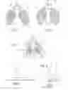
SHORT DESCRIPTION OF THE FIGURES
Further purposes and advantages of the present invention will be made clearer by the following detailed description of a manufactured example and by the attached drawings given for explanatory purposes in no way limited to these examples, wherein:
FIG. 1 shows a perspective view of an endonasal filter according to the present invention;
FIG. 2 shows a perspective view of a different version;
FIG. 3 shows a side view of a detail of connection between a spring for application of the filter and a filtering substrate;
FIGS. 4 and 5 show an example of how the endonasal device in FIG. 1 is fitted inside the nose.
DETAILED DESCRIPTION OF SOME PREFERRED FORMS OF REALIZING THE INVENTION
With reference to FIG. 1, it will be seen that the endonasal filter comprises two filtering components, 1 and 2, adjacent to each other, substantially flat and lunette-shaped, with between them a connecting element 3, acting as a spring. Element 3 is a single thread-like piece forming an arch, 4, the two ends of which are extended to become two parallel shanks 5 and 6 that reach as far as the two filtering components 1 and 2, and make perpendicular contact with the surfaces of said components. The shanks are then bent to form two oval-shaped elements 7 and 8 that rest on the filtering components lying closer to their inner edges than to their outer edges, and measuring about one quarter of the length of said components. The filtering components are thinner than the diameter of the thread-like arch 3, and adhere to the oval-shaped elements 7 and 8 resting on them. As far as concerns the material of the parts shown in the figure, this has already been explained above, as well as the geometrical dimensions and thicknesses.
According to a preferred form of realization, in which the connecting element 3 is made of plastic material as are the filtering components 1 and 2, said components 1 and 2 adhere to the oval-shaped elements 7 and 8 without the need for glue as it is sufficient to press them against the material while still hot in the press in order to fix them permanently.
FIG. 2 shows a variant in which, compared with the previous figure, the bases of the two shanks 5 and 6 consist of two small solid disks 9 and 10; these too can be made by moulding the same material as that of the shank, and then fixing them as above to the filtering components 1 and 2.
FIG. 3 shows how the shank 5, adhering to the filtering component 1, is bent to form oval element 7; the thicknesses shown here are close to reality. Although the filtering components 1 and 2 are so thin, the greater thickness of the oval parts 7 and 8, as well as their extension, together confer a certain degree of rigidity to the central area of filtering components 1 and 2, which helps to insert them to the required depth.
FIG. 4 illustrates an example of how the endonasal filter is applied. The figure shows the base of a nose 11, as seen from the nostrils 13 and 14, into which the two filtering components 1 and 2 have been inserted, joined by the central connecting element 3 placed across the cartilage 12 that separates the two nostrils. It will be seen that the shape of the filtering components 1 and 2 follows the outline of the nostrils 13 and 14 fairly closely and provides ample coverage when spread out.
In FIG. 5 the nose 11 is seen in profile, showing the connecting element 3 placed crosswise in relation to the cartilage 12, acting as a spring to keep the filtering components 1 and 2 in the position indicated by the dotted line. The filtering components 1 and 2 are inserted into the nostrils 13 and 14 by picking up the arch 4 between two fingers and pushing it inside the nose. This pressure widens the shanks 5 and 6 thus also altering the curve of the arch 4 which, being elastic, tends to return to its initial curve so exerting two opposing forces on the shanks 5 and 6; since these forces are both directed against the cartilage 12, the filter is thus kept in its correct position.
In the figure it will be seen that there is a slight adaptation inwards of the filtering component 2 (the same happens with component 1) as the intercepting surface is greater in relation to the section at the point of entry into the channel. This prevents unfiltered air from entering at the sides.
From the description given of a preferred realization, it is clear that changes can be made to it by competent persons without departing from the invention as described in the following claims.
Claims
1-11. (canceled)
12. Filtering device for air from the environment wherein two endonasal essentially planar filtering components (1, 2), are comprised:
said filtering components (1, 2) are lunette-shaped like the lumen on the channel giving access to the nasal cavities;
said filtering components (1, 2) are connected at respective ends of a flexible element (3), similar to a spring, applicable across the cartilage between the two nostrils;
said flexible element (3) comprises at each end means (7, 8, 9, 10) for joining it to the respective filtering component (1, 2),
wherein:
said joining means (7, 8, 9, 10) adhere to a surface of respective lunette-shaped filtering components (1, 2) in order to fix them permanently;
the surface area of each filtering component (1, 2) for intercepting incoming air is greater than the area of the section at entry to the endonasal channel, so it is partially bent inwards along the edge and fit closely against the wall of the lumen.
13. The device as in claims 12, wherein said flexible element (3) is a small U-shaped bar (4, 5, 6) with two shanks (5, 6) substantially perpendicular to the surfaces of the two filtering components (1, 2), and with said joining means (7, 8, 9, 10) lying on the plane of the filtering components (1, 2).
14. The device as in claim 13, wherein said joining means consist of the ends of the flexible element (3) curved to form two oval elements (7, 8).
15. The device as in claim 13, wherein said joining means consist of the ends of the flexible element (3) flattened to form two disks (9, 10).
16. The device as in claim 12 wherein said flexible element (3) is made of plastic material.
17. The device as in claim 12, wherein said flexible element (3) is made of steel wire.
18. The device as in claim 12, wherein the thickness of the filtering components (1, 2) is less than the thickness of the flexible element (3).
19. The device as in claim 13 wherein said flexible element (3) is made of plastic material.
20. The device as in claim 13, wherein said flexible element (3) is made of steel wire.
21. The device as in claim 13, wherein the thickness of the filtering components (1, 2) is less than the thickness of the flexible element (3).
22. The device as in claim 14 wherein said flexible element (3) is made of plastic material.
23. The device as in claim 14, wherein said flexible element (3) is made of steel wire.
24. The device as in claim 14, wherein the thickness of the filtering components (1, 2) is less than the thickness of the flexible element (3).
25. The device as in claim 15 wherein said flexible element (3) is made of plastic material.
26. The device as in claim 15, wherein said flexible element (3) is made of steel wire.
27. The device as in claim 15, wherein the thickness of the filtering components (1, 2) is less than the thickness of the flexible element (3).
28. The device as in claim 16, wherein the thickness of the filtering components (1, 2) is less than the thickness of the flexible element (3).
29. The device as in claim 17, wherein the thickness of the filtering components (1, 2) is less than the thickness of the flexible element (3).
Images & Drawings included:

Sources:
- United States Patent and Trademark Office - verify current appl. status at the USPTO↗
Recent applications in this class:
- » 20250222286 2025-07-10
GAS DELIVERY APPARATUS FOR NASAL APPLICATION - » 20240342519 2024-10-17
GAS PURIFICATION APPARATUS FOR NASAL APPLICATION - » 20240307715 2024-09-19
Nose Mask - » 20240115890 2024-04-11
Biodegradable Nose Filter - » 20240100371 2024-03-28
Nostril-shielding nasal mask and associated method(s) - » 20240091574 2024-03-21
NOSTRIL COVERING DEVICE - » 20240058632 2024-02-22
NASAL FILTER - » 20240024711 2024-01-25
Body-worn air-treatment devices and methods of deactivating pathogens - » 20240024710 2024-01-25
NOSE PLUG WITH ANTI-MICROBIAL ACTIVITY - » 20230293919 2023-09-21
AIR PURIFICATION APPARATUS FOR NASAL APPLICATION