Spinal midline indicator
US20100049040A1
2010-02-25
12/616,697
2009-11-11
✅ Patent granted
US 8,090,428 B2
2012-01-03
-
-
Long V. Le | Lawrence Laryea
2029-11-11
Abstract:
A spinal midline indicator (10) has a body (14) of radiolucent material for insertion between adjacent vertebrae (18, 20) and a radiographic marker (12) located centrally with the body to indicate the position of the spinal midline (22) in anterior-posterior images when the body is centrally located between the vertebrae. The radiographic marker is typically an elongate metal handle. The body may carry secondary radiographic markers (16) on opposite sides of and equidistant from the handle so that the handle indicates the position of the spinal midline when the body is placed centrally between the vertebrae.
Inventors:
- Malan de Villiers 88 🇿🇦 Wapadrand, South Africa
- Ulrich Reinhard Hahnle 10 🇿🇦 Saxonwold, South Africa
- Ulrich R. Hahnle 4 🇿🇦 Saxonwold, South Africa
Assignee:
- SpinalMotion, Inc. 64 🇺🇸 Mountain View, CA, United States
Interested in similar patents?
Get notified when new applications in this technology area are published.
Classification:
A61F2/44 » CPC further
Filters implantable into blood vessels; Prostheses, i.e. artificial substitutes or replacements for parts of the body; Appliances for connecting them with the body; Devices providing patency to, or preventing collapsing of, tubular structures of the body, e.g. stents; Prostheses implantable into the body; Joints for the spine, e.g. vertebrae, spinal discs
A61B17/025 » CPC main
Surgical instruments, devices or methods, e.g. tourniquets for holding wounds open; Tractors Joint distractors
A61B17/1671 » CPC further
Surgical instruments, devices or methods, e.g. tourniquets; Osteoclasts Bone cutting, breaking or removal means other than saws, e.g. ; Drills or chisels for bones; Trepans for particular parts of the body for the spine
A61B90/39 » CPC further
Instruments, implements or accessories specially adapted for surgery or diagnosis and not covered by any of the groups - , e.g. for luxation treatment or for protecting wound edges Markers, e.g. radio-opaque or breast lesions markers
A61F2/442 » CPC further
Filters implantable into blood vessels; Prostheses, i.e. artificial substitutes or replacements for parts of the body; Appliances for connecting them with the body; Devices providing patency to, or preventing collapsing of, tubular structures of the body, e.g. stents; Prostheses implantable into the body; Joints for the spine, e.g. vertebrae, spinal discs Intervertebral or spinal discs, e.g. resilient
A61F2/4657 » CPC further
Filters implantable into blood vessels; Prostheses, i.e. artificial substitutes or replacements for parts of the body; Appliances for connecting them with the body; Devices providing patency to, or preventing collapsing of, tubular structures of the body, e.g. stents; Prostheses implantable into the body; Joints; Special tools or methods for implanting or extracting artificial joints, accessories, bone grafts or substitutes, or particular adaptations therefor Measuring instruments used for implanting artificial joints
A61B17/1757 » CPC further
Surgical instruments, devices or methods, e.g. tourniquets; Osteoclasts Bone cutting, breaking or removal means other than saws, e.g. ; Drills or chisels for bones; Trepans; Guides for drills specially adapted for particular parts of the body for the spine
A61B2017/0256 » CPC further
Surgical instruments, devices or methods, e.g. tourniquets for holding wounds open; Tractors; Joint distractors for the spine
A61B2090/3916 » CPC further
Instruments, implements or accessories specially adapted for surgery or diagnosis and not covered by any of the groups - , e.g. for luxation treatment or for protecting wound edges; Markers, e.g. radio-opaque or breast lesions markers specially adapted for marking specified tissue Bone tissue
A61F2002/3008 » CPC further
Filters implantable into blood vessels; Prostheses, i.e. artificial substitutes or replacements for parts of the body; Appliances for connecting them with the body; Devices providing patency to, or preventing collapsing of, tubular structures of the body, e.g. stents; Prostheses implantable into the body; Joints; Additional features of subject-matter classified in , and subgroups thereof; Material related properties of the prosthesis or of a coating on the prosthesis; Properties of materials and coating materials radio-opaque, e.g. radio-opaque markers
A61F2002/4658 » CPC further
Filters implantable into blood vessels; Prostheses, i.e. artificial substitutes or replacements for parts of the body; Appliances for connecting them with the body; Devices providing patency to, or preventing collapsing of, tubular structures of the body, e.g. stents; Prostheses implantable into the body; Joints; Special tools or methods for implanting or extracting artificial joints, accessories, bone grafts or substitutes, or particular adaptations therefor; Measuring instruments used for implanting artificial joints for measuring dimensions, e.g. length
A61F2250/0098 » CPC further
Special features of prostheses classified in groups - or or or or subgroups thereof; Additional features; Implant or prostheses properties not otherwise provided for; Markers and sensors for detecting a position or changes of a position of an implant, e.g. RF sensors, ultrasound markers radio-opaque, e.g. radio-opaque markers
A61B17/56 IPC
Surgical instruments, devices or methods, e.g. tourniquets Surgical instruments or methods for treatment of bones or joints; Devices specially adapted therefor
A61B5/05 IPC
Measuring for diagnostic purposes ; Identification of persons Detecting, measuring or recording for diagnosis by means of electric currents or magnetic fields; Measuring using microwaves or radio waves
Description
CROSS-REFERENCES TO RELATED APPLICATIONS
This application is a continuation of U.S. Ser. No. 11/187,733 filed Jul. 21, 2005, which application is a continuation of International Application PCT/IB2004/000170 filed on Jan. 26, 2004, which claimed priority from South African application 2003/0874 filed on Jan. 31, 2003; the full disclosures, each of which are incorporated herein by reference in their entirety.
BACKGROUND OF THE INVENTION
This invention relates to a spinal midline indicator.
It is important for a surgeon performing an ALIF (anterior lumbar interbody fusion) or ACIF (anterior cervical interbody fusion) cage or spinal disc replacement procedure to be able accurately to establish the centre- or midline of the spine. It is only once the surgeon has correctly established the position of the spinal midline that he is able to place the cage or spinal disc accurately on that midline. ff-centre placement will result in eccentric loading and possible early failure or accelerated wear.
At present, surgeons attempt to establish the spinal midline by visual inspection of an A-P (anterior-posterior) image. However this is often inaccurate, and can lead to subsequent off-centre placement of the cage or disc with potential disadvantages as described above.
The present invention seeks to provide an instrument which will facilitate accurate establishment of the spinal midline.
BRIEF SUMMARY OF THE INVENTION
According to the present invention there is provided a spinal midline indicator comprising a body of radiolucent material for insertion between adjacent vertebrae and a radiographic marker associated centrally with the body to indicate, in an anterior-posterior radiographic image, the position of the spinal midline when the body is appropriately located between the vertebrae. Conveniently the radiographic marker is an elongate handle which is connected to the body to facilitate placement of the body between the vertebrae and which is made of a radiographic material, i.e., a material which is substantially opaque to radiographic (fluoroscopic) imaging.
In the preferred embodiment, the body carries, in addition to the handle which serves as a first radiographic marker, two or more secondary radiographic markers on opposite sides of and equidistant from the first marker, whereby the first marker indicates the position of the spinal midline when the body is placed centrally between the vertebrae and the secondary markers are seen in the radiographic image to be equidistant from lateral edges of the vertebrae.
Further according to the invention there is provided a method of identifying a spinal midline which comprises the steps of inserting the body of a spinal midline indicator as summarized above between adjacent spinal vertebrae, manipulating the body so that the radiographic marker is seen in a radiographic image to be on the spinal midline, and, using the position of the radiographic marker as a guide, applying a marking, eg. a pin, to a vertebra to indicate the midline.
Other features of the invention are set forth in the appended claims.
BRIEF DESCRIPTION OF THE DRAWINGS
The invention will now be described in more detail, by way of example only, with reference to the accompanying drawings.
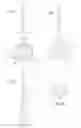
FIG. 1 shows a perspective view of a spinal midline indicator according to the invention;
FIG. 2 shows a side view of the indicator in the direction of the arrow 2 in FIG. 1;
FIG. 3 shows a side view of the indicator in the direction of the arrow 3 in FIG. 1;
FIG. 4 shows an end view of the indicator in the direction of the arrow 4 in FIG. 1;
FIG. 5 diagrammatically illustrates the indicator in use; and
FIG. 6 shows a diagrammatic cross-section at the line 6-6 in FIG. 5.
DETAILED DESCRIPTION OF THE INVENTION
The spinal midline indicator 10 seen in FIGS. 1 to 4 includes an elongate handle 12 and a body 14 carried centrally at one end of the handle. The handle is made of a radiographic material, i.e. one which is opaque to radiation in the radiowave part of the spectrum, including X-radiation. The handle may, for instance, be made of stainless steel or titanium. The handle 12 extends substantially through the body 14. The body 14 is made of a radiolucent material, i.e. one which is at least to some degree transparent to the radiation. The body may, for instance, be made of PEEK (polyetheretherketone) or UHMWPE (ultra-high molecular weight polyethylene).
Embedded in the body 14 are two elongate markers 16, also of radiographic material such as stainless steel or titanium. The markers 16 are aligned parallel to the handle 12 and are located on opposite sides of, and equidistant from the handle.
FIG. 5 diagrammatically illustrates, in an anterior view, adjacent upper and lower vertebrae 18 and 20 respectively. As explained above it is important, during an ALIF or ACIF cage or spinal disc replacement procedure carried out anteriorly, for the surgeon to be able accurately to establish the spinal midline, indicated by the line 22, since it is centrally on this line that the replacement disc or cage must be placed. The procedure is typically carried out, with the patient lying prone and flat on his back, through a frontal incision.
In order to establish the midline 22, the surgeon aligns the handle 12 at a vertical orientation and uses it to insert the body 14 between the vertebrae 18 and 20. It will be understood that a separate instrument 100 is used to hold the vertebrae apart for this insertion to take place. An attempt is made to orientate the body centrally with the handle 12 vertical, thereby to ensure that the handle correctly indicates the midline 22.
An X-ray photograph or radiographic image is taken in the vertical anterior-posterior direction. In this radiographic image the handle 12, markers 16 and vertebrae 18,20 will be visible. By ensuring that the markers 16 are equidistantly laterally spaced from the osseous edges 23 of the vertebrae, i.e. that the distance 25 is the same on both sides, the surgeon can ensure that the body 14 and handle 12 are centrally positioned. It will be understood that during this procedure, the handle 12 itself operates as a radiographic marker indicating a central position.
It will also be understood that if the handle 12 and markers 16 are aligned with the anterior-posterior direction in which the radiographic image is taken, they will appear in the radiographic image merely as dots of small lateral dimension. However if the handle is not perfectly aligned in the anterior-posterior, i.e. vertical direction, parallax effects will result in the handle and markers being seen as lines rather than dots.
This is illustrated in FIG. 6 in which the full lines show the handle 10 at the correct anterior-posterior or vertical orientation and the broken lines show it at orientations in which it is misaligned by an angle 9. It will be understood that in a radiographic image in the anterior-posterior direction indicated by the arrow 24, the handle 12 and markers 16 will appear as dots at the full line orientation but as short lines at the broken line orientations.
By consulting radiographic images and manipulating the indicator 10 as necessary in response to the information derived therefrom, the surgeon can ensure that the indicator is at the correct position and orientation. When the indicator is in the correct position and at the correct orientation, the handle 12 will lie in a vertical plane containing the midline 22. The surgeon can now use the handle as a positive indicator of that midline. The position of the radiographic marker can be used as a guide to apply a marking to a vertebra to indicate the midline. He can accurately mark the midline, for instance by knocking a pin 26 into one of the vertebrae.
Once the midline has been marked on one or both of the vertebrae, the indicator 10 is no longer required and can be removed for later re-use. The marker(s) then serve to indicate the midline 22 to enable subsequent, accurate positioning of the relevant prosthesis to take place.
Claims
What is claimed is:1. A spinal midline indicator comprising:
a body of radiolucent material sized and shaped to fit into an intervetebral space between two adjacent vertebrae; and
a radiographic marker formed as an elongated handle attached to and extending from the body along a central axis of the body in an anterior-posterior direction, wherein the handle is embedded in the body.
2. A spinal midline indicator according to claim 1, further comprising at least two secondary radiographic markers on opposite sides of the elongated handle and located equidistant from the elongate handle and from lateral edges of the body.
3. A spinal midline indicator according to claim 1, wherein the handle is made of stainless steel or titanium.
4. A spinal midline indicator according to claim 2, wherein the secondary radiographic markers are embedded in the body.
5. A spinal midline indicator according to claim 1, wherein the body has a length in a direction of the handle which is smaller than a width in a direction perpendicular to the length.
6. A spinal midline indicator according to claim 1, wherein the handle extends substantially through the body.
7. A spinal midline indicator to identify a spinal midline, the indicator comprising:
a body of radiolucent material sized and shaped to fit into an intervetebral space between two adjacent vertebrae; and
a radiographic marker centrally disposed within the body and extending from the body to guide a marking applied to the midline of at least one of the two adjacent vertebrae, wherein the marker comprises a handle embedded in the body.
8. A spinal midline indicator according to claim 7, further comprising at least two secondary radiographic markers on opposite sides of the elongated handle and located equidistant from the elongate handle and from lateral edges of the body.
9. A spinal midline indicator according to claim 7, wherein the handle is made of stainless steel or titanium.
10. A spinal midline indicator according to claim 8, wherein the secondary radiographic markers are embedded in the body.
11. A spinal midline indicator according to claim 7, wherein the marker extends substantially through the body.
Images & Drawings included:


Sources:
- United States Patent and Trademark Office - verify current appl. status at the USPTO↗
Similar patent applications:
- » 20060029186
Spinal midline indicator - » 20120078374
SPINAL MIDLINE INDICATOR
Recent applications in this class:
- » 20250288287 2025-09-18
SYSTEMS AND METHODS FOR PERFORMING SPINE SURGERY - » 20250268589 2025-08-28
NEUROMONITORING DILATORS, PROBES, AND CANNULATED BLADES FOR MODULAR TISSUE RETRACTOR - » 20250261934 2025-08-21
RETRACTOR DISTRACTOR BLADE SYSTEM - » 20250255597 2025-08-14
SERIES OF INSTRUMENTS FOR EXPOSURE OF LESIONS POSTERIOR TO TALUS DOME - » 20250248703 2025-08-07
EXPANDABLE INTERSPINOUS-INTERLAMINAR STABILIZATION SYSTEMS AND METHODS - » 20250248702 2025-08-07
EXPANDABLE INTERSPINOUS-INTERLAMINAR STABILIZATION SYSTEMS AND METHODS - » 20250241633 2025-07-31
Distraction Device With Disposable Force Sensor Pod - » 20250235195 2025-07-24
Retractor blade devices and related methods - » 20250228544 2025-07-17
Anterior to Psoas Instrumentation - » 20250221699 2025-07-10
INSERTION INSTRUMENTS
Recent applications for this Assignee:
- » 20140277475 2014-09-18
Intervertebral prosthetic disc - » 20140257493 2014-09-11
Artificial intervertebral disc with lower height - » 20140128976 2014-05-08
Prosthetic disc for intervertebral insertion - » 20130297026 2013-11-07
Customized intervertebral prosthetic disc with shock absorption - » 20130274880 2013-10-17
Anatomy accomodating prosthetic intervertebral disc with lower height - » 20130013073 2013-01-10
METHODS AND APPARATUS FOR INTERVERTEBRAL DISC PROSTHESIS - » 20130013072 2013-01-10
INTERVERTEBRAL PROSTHETIC DISC - » 20130013069 2013-01-10
Intervertebral prosthetic disc - » 20120232662 2012-09-13
Artificial intervertebral disc placement system - » 20120101579 2012-04-26
PROSTHETIC INTERVERTEBRAL DISC WITH MOVABLE CORE