Centralized Energy Management in Distributed Systems
US20100100252A1
2010-04-22
12/255,506
2008-10-21
Abstract:
A distributed system of appliances that comprises a centralized energy-use controller to coordinate the use of energy among a plurality of distributed and interconnected appliances is disclosed. For example, the centralized controller directs when each appliance refrains from using energy from its energy-storage device during intervals when the energy-storage device is capable of providing energy to the appliance but the centralized power supply is not, and when each appliance can consume energy from its energy-storage device during intervals when both the energy-storage device and the centralized power supply are capable of providing power to the appliance.
Inventors:
- Paul Roller Michaelis 111 🇺🇸 Louisville, CO, United States
- Howard G. Kradjel 3 🇺🇸 Lincroft, NJ, United States
- Robert Laurence Greenberg 1 🇺🇸 Red Bank, NJ, United States
Assignee:
- Avaya Inc 1,741 🇺🇸 Basking Ridge, NJ, United States
Interested in similar patents?
Get notified when new applications in this technology area are published.
Classification:
H02J3/14 » CPC main
Circuit arrangements for ac mains or ac distribution networks for adjusting voltage in ac networks by changing a characteristic of the network load by switching loads on to, or off from, network, e.g. progressively balanced loading
H02J3/28 » CPC further
Circuit arrangements for ac mains or ac distribution networks Arrangements for balancing of the load in a network by storage of energy
H02J13/00006 » CPC further
Circuit arrangements for providing remote indication of network conditions, e.g. an instantaneous record of the open or closed condition of each circuitbreaker in the network; Circuit arrangements for providing remote control of switching means in a power distribution network, e.g. switching in and out of current consumers by using a pulse code signal carried by the network characterised by information or instructions transport means between the monitoring, controlling or managing units and monitored, controlled or operated power network element or electrical equipment
H02J13/0013 » CPC further
Circuit arrangements for providing remote indication of network conditions, e.g. an instantaneous record of the open or closed condition of each circuitbreaker in the network; Circuit arrangements for providing remote control of switching means in a power distribution network, e.g. switching in and out of current consumers by using a pulse code signal carried by the network for single frequency AC networks characterised by transmission structure between the control or monitoring unit and the controlled or monitored unit
H02J2310/58 » CPC further
The network for supplying or distributing electric power characterised by its spatial reach or by the load for selectively controlling the operation of the loads characterised by the condition upon which the selective controlling is based The condition being electrical
Y02B70/3225 » CPC further
Technologies for an efficient end-user side electric power management and consumption; Systems integrating technologies related to power network operation and communication or information technologies for improving the carbon footprint of the management of residential or tertiary loads, i.e. smart grids as climate change mitigation technology in the buildings sector, including also the last stages of power distribution and the control, monitoring or operating management systems at local level Demand response systems, e.g. load shedding, peak shaving
Y02B90/20 » CPC further
Enabling technologies or technologies with a potential or indirect contribution to GHG emissions mitigation Smart grids as enabling technology in buildings sector
Y02B90/20 » CPC further
Enabling technologies or technologies with a potential or indirect contribution to GHG emissions mitigation Smart grids as enabling technology in buildings sector
Y04S20/12 » CPC further
Management or operation of end-user stationary applications or the last stages of power distribution; Controlling, monitoring or operating thereof Energy storage units, uninterruptible power supply [UPS] systems or standby or emergency generators, e.g. in the last power distribution stages
Y04S20/222 » CPC further
Management or operation of end-user stationary applications or the last stages of power distribution; Controlling, monitoring or operating thereof; End-user application control systems Demand response systems, e.g. load shedding, peak shaving
Y04S40/12 » CPC further
Systems for electrical power generation, transmission, distribution or end-user application management characterised by the use of communication or information technologies, or communication or information technology specific aspects supporting them characterised by data transport means between the monitoring, controlling or managing units and monitored, controlled or operated electrical equipment
G06F1/00 IPC
Details not covered by groups - and
Description
FIELD OF THE INVENTION
The present invention relates to energy management in general, and, more particularly, to the centralized management of distributed and interconnected appliances.
BACKGROUND OF THE INVENTION
Energy is expensive, and, therefore, the need exists for more energy-efficient products.
SUMMARY OF THE INVENTION
The present invention affects energy-efficiency in a distributed system of appliances without some of the costs and disadvantages for doing so in the prior art. For example, the illustrative embodiment comprises a centralized energy-use controller to coordinate the use of energy among a plurality of distributed and interconnected appliances. The coordination of the use of energy among the appliances enables efficiencies that are not possible otherwise.
For example, the centralized controller directs:
-
- i. when each appliance consumes energy from a centralized power supply, and
- ii. when each appliance consumes energy from an energy-storage device that is associated with the appliance, and
- iii. when each appliance recharges its energy-storage device with power from the centralized power supply, and
- iv. when each appliance transmits energy from its energy-storage device to the centralized power supply for use by another appliance, and
- v. when each appliance refrains from using energy from its energy-storage device during intervals when the energy-storage device is capable of providing energy to the appliance but the centralized power supply is not, and
- vi. when each appliance can consume energy from its energy-storage device during intervals when both the energy-storage device and the centralized power supply are capable of providing power to the appliance, and
- vii. when each appliance can consume energy for one use and when each appliance cannot consume energy for a second use.
This enables the controller to reduce the total amount of power consumed by the system as a whole while deliberately choosing which appliances use power and for what uses.
The illustrative embodiment comprises: (1) a first appliance associated with a first energy-storage device; (2) a second appliance associated with a second energy-storage device; (3) a power supply for providing energy to the first appliance and the second appliance; and (4) an energy-use controller for directing: (i) when the first appliance consumes energy from the power supply, (ii) when the first appliance consumes energy from the first energy-storage device, and (iii) when the first appliance recharges the first energy-storage device, (iv) when the second appliance consumes energy from the power supply, (v) when the second appliance consumes energy from the second energy-storage device, and (vi) when the second appliance recharges the second energy-storage device.
BRIEF DESCRIPTION OF THE DRAWINGS
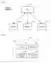
FIG. 1 depicts a block diagram of the salient components of a distributed system in accordance with the illustrative embodiment.
FIG. 2 depicts a block diagram of the salient components of hub 101 in accordance with the illustrative embodiment.
FIG. 3 depicts a block diagram of the salient components of appliance 102-i in accordance with the illustrative embodiment of the present invention.
FIG. 4 depicts a flowchart of the salient tasks associated with the operation of the illustrative embodiment of the present invention.
FIG. 5 depicts a flowchart of the salient tasks associated with the operation of task 401-i.
DETAILED DESCRIPTION
FIG. 1 depicts a block diagram of the salient components of distributed system 100 in accordance with the illustrative embodiment of the present invention. Distributed system 100 comprises: hub 101 and appliances 102-1 through 102-3, interconnected as shown. In accordance with the illustrative embodiment, distributed system 100 is a telecommunications system, but it will be clear to those skilled in the art, after reading this disclosure, how to make and use alternative embodiments of the present invention that provide another function.
Although the illustrative embodiment has a star topology, it will be clear to those skilled in the art, after reading this disclosure, how to make and use alternative embodiments of the present invention that have any topology (e.g., ring, mesh, etc.).
Although the illustrative embodiment comprises three appliances, it will be clear to those skilled in the art, after reading this disclosure, how to make and use alternative embodiments of the present that comprise any number of appliances.
Although the illustrative embodiment comprises one “hub,” it will be clear to those skilled in the art, after reading this disclosure, how to make and use alternative embodiments of the present invention that comprise any number of hubs.
Hub 101 comprises hardware and software for providing energy to appliances 102-1 through 102-3, for controlling the use of energy by appliances 102-1 through 102-3, and for coordinating communications among appliances 102-1 through 102-3. The details of hub 101 are described in detail below and in the accompanying figures.
Appliance 102-i, wherein i ∈ {1, 2, 3}, is hardware and software for providing telecommunications service to its user. Although appliance 102-i functions as a telecommunications terminal, it will be clear to those skilled in the art, after reading this disclosure, how to make and use alternative embodiments of the present invention in which appliance 102-i performs another function.
The details of appliance 102-i are described in detail below and in the accompanying figures.
FIG. 2 depicts a block diagram of the salient components of hub 101 in accordance with the illustrative embodiment. Hub 101 comprises: switch 201, power supply 202, energy-use controller 203, and energy-storage device 204.
In accordance with the illustrative embodiment, hub 101 is the switch for distributed system 100, but it will be clear to those skilled in the art, however, after reading this disclosure, how to make and use alternative embodiments of the present invention in which hub 101 performs another function.
In accordance with the illustrative embodiment, hub physically houses switch 201, power supply 202, energy-use controller 203, and energy-storage device 204 but it will be clear to those skilled in the art, after reading this disclosure, how to make and use alternative embodiments of the present invention in some or all of these components are separately housed.
Switch 201 is hardware and software for coordinating telecommunications for appliances 102-1, 102-2, and 102-3. It is clear to those skilled in the art how to make and use switch 201.
Power supply 202 is hardware for providing energy to hub 101 and appliances 102-1 through 102-3 from an external source that is not shown in the figures. It is clear to those skilled in the art how to make and use power supply 202.
Energy-use controller 203 is hardware and software for directing how and when appliance 102-i consumes and uses energy. The details of energy-use controller 203 are described below and in the accompanying figures.
Energy-storage device 204 is hardware for storing energy for use by hub 101 and appliance 102-i. It is clear to those skilled in the art how to make and use energy-storage device 204.
FIG. 3 depicts a block diagram of the salient components of appliance 102-i in accordance with the illustrative embodiment of the present invention. Appliance 102-i comprises: energy-storage device 301-i, energy-use regulator 302-i, and telecom equipment 303-i.
Energy-storage device 301-i is hardware for storing energy in well-known fashion.
Energy-use regulator 302-i is hardware and software for:
-
- i. receiving directions from energy-use controller 203 for how and when appliance 102-i can use and consume energy, and
- ii. transmitting statistics to energy-use controller 203 on the use and consumption of energy by appliance 102-i, and
- iii. controlling when appliance 102-i consumes energy from the power supply 302 (under the direction of energy-use controller 203), and
- iv. controlling when appliance 102-i consumes energy from energy-storage device 401-i (under the direction of energy-use controller 203), and
- v. controlling when appliance 102-i recharges energy-storage device 401-i (under the direction of energy-use controller 203), and
- vi. controlling when appliance 102-i transmits energy from energy-storage device 104-i to hub 101 (under the direction of energy-use controller 203).
It will be clear to those skilled in the art, after reading this specification, how to make and use energy-use regulator 302-i.
Telecom equipment 303-i is hardware and software for enabling a user of appliance 102-i to telecommunicate. It is well known to those skilled in the art how to make and use telecom equipment 303-i.
FIG. 4 depicts a flowchart of the salient tasks associated with the operation of the illustrative embodiment of the present invention. In accordance with the illustrative embodiment, energy-use controller 203 performs tasks 401-1, 401-2, and 401-3 concurrently. It will be clear to those skilled in the art, however, after reading this disclosure, how to make and use alternative embodiments of the present invention in which tasks 401-1, 401-2, and 401-3 are not performed concurrently (e.g., are performed serially, etc.).
At task 401-1, energy-use controller 303 directs how and when appliance 101-1 consumes and manages energy. The details of task 401-1 are described below and in the accompanying figures.
At task 401-2, energy-use controller 303 directs how and when appliance 101-2 consumes and manages energy. The details of task 401-2 are described below and in the accompanying figures.
At task 401-3, energy-use controller 303 directs how and when appliance 101-3 consumes and manages energy. The details of task 401-3 are described below and in the accompanying figures.
FIG. 5 depicts a flowchart of the salient tasks associated with the operation of task 401-i.
At task 501, energy-use controller 501-i directs how and when energy consuming appliance 101-i consumes energy from energy supply 202.
At task 502, energy-use controller 501-i directs how and when energy consuming appliance 101-i consumes energy from energy-storage device 301-i.
At task 503, energy-use controller 501-i directs how and when appliance 101-i recharges energy-storage device 301-i with energy from power supply 302.
At task 504, energy-use controller 501-i directs how and when appliance 101-i transmits energy from energy-storage device 301-i to power supply 302.
At task 505, energy-use controller 501-i directs how and when appliance 101-i consumes energy from energy-storage device 301-i when both power supply 302 and energy-storage device 301-i are capable of providing energy to appliance 101-i.
At task 506, energy-use controller 501-i directs how and when appliance 101-i refrains from consuming energy from energy-storage device 301-i when energy-storage device 301-i is capable of providing energy to appliance 101-i and power supply 302 is not capable of providing energy to appliance 101-i.
At task 507, energy-use controller 501-i directs that appliance 101-i is to consume energy for a first use and not consume energy for a second use.
It is to be understood that the disclosure teaches just one example of the illustrative embodiment and that many variations of the invention can easily be devised by those skilled in the art after reading this disclosure and that the scope of the present invention is to be determined by the following claims.
Claims
1. A system comprising:
(1) a first appliance associated with a first energy-storage device;
(2) a second appliance associated with a second energy-storage device;
(3) a power supply for providing energy to the first appliance and the second appliance; and
(4) an energy-use controller for directing:
(i) when the first appliance consumes energy from the power supply,
(ii) when the first appliance consumes energy from the first energy-storage device, and
(iii) when the first appliance recharges the first energy-storage device,
(iv) when the second appliance consumes energy from the power supply,
(v) when the second appliance consumes energy from the second energy-storage device, and
(vi) when the second appliance recharges the second energy-storage device.
2. The system of claim 1 wherein the controller also directs:
(vii) when the first appliance takes energy from the first energy-storage device during intervals when both the power supply and the first energy-storage device are capable of providing energy to the first appliance, and
(viii) when the second appliance takes energy from the second energy-storage device during intervals when both the power supply and the second energy-storage device are capable of providing energy to the second appliance.
3. (canceled)
4. The system of claim 1 wherein the controller also directs:
(vii) when the first appliance is to refrain from taking energy from the first energy-storage device during intervals when the first energy-storage device is capable of providing energy to the first appliance but the power supply is not capable of providing energy to the first device, and
(viii) when the second appliance is to refrain from taking energy from the second energy-storage device during intervals when the second energy-storage device is capable of providing energy to the second appliance but the power supply is not capable of providing energy to the second device.
5. The system of claim 1 wherein the controller also directs:
(vii) the first appliance to consume energy for a first use and to refrain from consuming energy for a second use, and
(viii) the second appliance to consume energy for the first use and to refrain from consuming energy for the second use.
6. The system of claim 1 further comprising (5) a telecommunications switch for coordinating communication between the first appliance and the second appliance.
7. A method comprising:
directing when a first appliance takes energy from a first energy-storage device during intervals when both a power supply and the first energy-storage device are capable of providing energy to the first appliance; and
directing when a second appliance takes energy from a second energy-storage device during intervals when both the power supply and the second energy-storage device are capable of providing energy to the second appliance.
8. (canceled)
9. The method of claim 7 further comprising:
directing when the first appliance is to refrain from taking energy from the first energy-storage device during intervals when the first energy-storage device is capable of providing energy to the first appliance but the power supply is not capable of providing energy to the first device, and
directing when the second appliance is to refrain from taking energy from the second energy-storage device during intervals when the second energy-storage device is capable of providing energy to the second appliance but the power supply is not capable of providing energy to the second device.
10. The method of claim 7 further comprising:
directing the first appliance to consume energy for a first use and to refrain from consuming energy for a second use, and
directing the second appliance to consume energy for the first use and to refrain from consuming energy for the second use.
11. A method comprising:
directing when a first appliance is to refrain from taking energy from a first energy-storage device during intervals when a first energy-storage device is capable of providing energy to the first appliance but a power supply is not capable of providing energy to the first device, and
directing when a second appliance is to refrain from taking energy from a second energy-storage device during intervals when the second energy-storage device is capable of providing energy to the second appliance but the power supply is not capable of providing energy to the second device.
12. (canceled)
13. The method of claim 11 further comprising:
directing the first appliance to consume energy for a first use and to refrain from consuming energy for a second use, and
directing the second appliance to consume energy for the first use and to refrain from consuming energy for the second use.
14. The method of claim 11 further comprising coordinating communication between the first appliance and the second appliance.
15. A method comprising directing from a controller:
(i) when a first appliance can consume energy from a power supply, a first energy-storage device, and a second energy-storage device, and
(ii) when a second appliance can consume energy from the power supply, the first energy-storage device, and the second energy-storage device, and
(iii) when the first appliance recharges the first energy-storage device with energy from the power supply, and
(iv) when the second appliance recharges the second energy-storage device with energy from the power supply.
16. The method of claim 15 further comprising directing from the controller:
(v) when the first appliance takes energy from the first energy-storage device during intervals when both the power supply and the first energy-storage device are capable of providing energy to the first appliance, and
(vi) when the second appliance takes energy from the second energy-storage device during intervals when both the power supply and the second energy-storage device are capable of providing energy to the second appliance.
17. (canceled)
18. The method of claim 15 further comprising directing from the controller:
(v) when the first appliance is to refrain from taking energy from the first energy-storage device during intervals when the first energy-storage device is capable of providing energy to the first appliance but the power supply is not capable of providing energy to the first device, and
(vi) when the second appliance is to refrain from taking energy from the second energy-storage device during intervals when the second energy-storage device is capable of providing energy to the second appliance but the power supply is not capable of providing energy to the second device.
19. The method of claim 15 further comprising directing from the controller:
(v) the first appliance to consume energy for a first use and to refrain from consuming energy for a second use, and
(vi) the second appliance to consume energy for the first use and to refrain from consuming energy for the second use.
Images & Drawings included:


Sources:
- United States Patent and Trademark Office - verify current appl. status at the USPTO↗
Recent applications in this class:
- » 20250174994 2025-05-29
CONTROLLING GRID COMPONENTS OF AN ELECTRIC POWER GRID - » 20250174993 2025-05-29
ELECTRONIC CONTROLLER AND COMMUNICATION SYSTEM - » 20250158405 2025-05-15
SMART SWITCHING PANEL FOR SECONDARY POWER SUPPLY - » 20250158404 2025-05-15
POWER MANAGEMENT SYSTEM AND POWER MANAGEMENT METHOD - » 20250158403 2025-05-15
PREDICTIVE POWER DISTRIBUTION UNIT OUTPUT LOAD SWITCHING FOR INPUT PHASE BALANCING - » 20250132563 2025-04-24
METHOD FOR DISCHARGE CONTROL OF FULL-BUS LOAD IN HOUSEHOLD APPLIANCE, AND RELATED APPARATUSES - » 20250125618 2025-04-17
PROACTIVE INTELLIGENT LOAD SHEDDING - » 20250112464 2025-04-03
Coordinated Feedback Mechanism and Methods - » 20250070554 2025-02-27
POWER PLANT HAVING A FLEXIBLE FIRM SKID - » 20250038531 2025-01-30
Method and Apparatus for Electrical Load Control Network
Recent applications for this Assignee:
- » 20210176204 2021-06-10
System and method for managing trusted relationships in communication sessions using a graphical metaphor - » 20210144254 2021-05-13
Immediate call reconnection to a user of a disconnected client system - » 20210037068 2021-02-04
Creation and sharing of contacts groups between communication participants - » 20200275175 2020-08-27
Clip based speaker retention to a mounting surface - » 20200153940 2020-05-14
Services versioning - » 20190273821 2019-09-05
Real-time speech feed to agent greeting - » 20190253555 2019-08-15
Systems and methods for placing calls in a non-disturbing manner - » 20190199968 2019-06-27
Disturbance detection in video communications - » 20190196433 2019-06-27
Remote user interface actuation using a piezoelectric grid - » 20190058744 2019-02-21
Systems and methods for providing automated progress updates in a contact center