Keypad assembly and portable electronic device using same
US20100103111A1
2010-04-29
12/354,904
2009-01-16
✅ Patent granted
US 8,228,313 B2
2012-07-24
-
-
Van Chow
2031-04-22
Abstract:
A keypad assembly includes a keypad cover, a printed circuit board and a sensing module. The sensing module is arranged between the keypad cover and the printed circuit board. The sensing module is used to sense touches of a user's finger on the keypad cover. A portable electronic device equipped with the keypad assembly is also described.
Inventors:
- CHIH-PU HSU 4 🇹🇼 Tu-Cheng, Taiwan
- JIUN-CHING WU 1 🇹🇼 Tu-Cheng, Taiwan
- Jiun-Ching Wu 1 🇹🇼 Taipei County, Taiwan
- Chih-Pu Hsu 1 🇹🇼 Taipei County, Taiwan
Assignee:
- CHI MEI COMMUNICATION SYSTEMS, INC. 604 🇹🇼 Tu-Cheng City, Taiwan
- Chi Mei Communication Systems, Inc. 218 🇹🇼 Tu-Cheng, New Taipei, Taiwan
Interested in similar patents?
Get notified when new applications in this technology area are published.
Classification:
H01H13/85 » CPC main
Switches having rectilinearly-movable operating part or parts adapted for pushing or pulling in one direction only, e.g. push-button switch having a plurality of operating members associated with different sets of contacts, e.g. keyboard characterised by ergonomic functions, e.g. for miniature keyboards; characterised by operational sensory functions, e.g. sound feedback characterised by tactile feedback features
H01H13/705 » CPC further
Switches having rectilinearly-movable operating part or parts adapted for pushing or pulling in one direction only, e.g. push-button switch having a plurality of operating members associated with different sets of contacts, e.g. keyboard with contacts carried by or formed from layers in a multilayer structure, e.g. membrane switches characterised by construction, mounting or arrangement of operating parts, e.g. push-buttons or keys
H01H2003/0293 » CPC further
Mechanisms for operating contacts; Operating parts, i.e. for operating driving mechanism by a mechanical force external to the switch with an integrated touch switch
H01H2217/032 » CPC further
Facilitation of operation; Human engineering Feedback about selected symbol, e.g. display
H01H2217/033 » CPC further
Facilitation of operation; Human engineering; Feedback about selected symbol, e.g. display by speech
H01H2225/002 » CPC further
Switch site location superimposed
H01H2225/03 » CPC further
Switch site location Different type of switches
H01H2239/074 » CPC further
Miscellaneous Actuation by finger touch
G06F3/02 IPC
Input arrangements for transferring data to be processed into a form capable of being handled by the computer; Output arrangements for transferring data from processing unit to output unit, e.g. interface arrangements; Input arrangements or combined input and output arrangements for interaction between user and computer Input arrangements using manually operated switches, e.g. using keyboards or dials
G06F3/045 IPC
Input arrangements for transferring data to be processed into a form capable of being handled by the computer; Output arrangements for transferring data from processing unit to output unit, e.g. interface arrangements; Input arrangements or combined input and output arrangements for interaction between user and computer; Arrangements for converting the position or the displacement of a member into a coded form; Digitisers, e.g. for touch screens or touch pads, characterised by the transducing means using resistive elements, e.g. a single continuous surface or two parallel surfaces put in contact
Description
BACKGROUND
1. Field of the invention
The present invention relates to keypad assemblies, and particularly, to a keypad assembly used in a portable electronic device.
2. Description of related art
Portable electronic devices (e.g., mobile phones and digital cameras) are becoming smaller and thinner.
Thus, a mini keypad assembly is needed to meet small and thin demands. However, the symbols/numbers printed on the keypad assembly may become too small to read.
Therefore, there is room for improvement within the art.
BRIEF DESCRIPTION OF THE DRAWINGS
Many aspects of a keypad assembly can be better understood with reference to the following drawings. These drawings are not necessarily drawn to scale, the emphasis instead being placed upon clearly illustrating the principles of the present keypad assembly.
Moreover, in the drawings like reference numerals designate corresponding sections throughout a plurality of views.
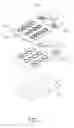
FIG. 1 is an isometric, exploded view of a keypad assembly, according to an exemplary embodiment.
FIG. 2 is another isometric, exploded view of the keypad assembly shown in FIG. 1.
FIG. 3 is an isometric, assembled view of the keypad assembly shown in FIG. 1.
FIG. 4 is a schematic view showing a portable electronic device equipped with the keypad assembly shown in FIG. 1.
DETAILED DESCRIPTION OF EXEMPLARY EMBODIMENT
FIG. 1 shows an exemplary keypad assembly 10. The keypad assembly 10 is used in a portable electronic device 20 (schematically shown in FIG. 4), such as a mobile phone or a personal digital assistant (PDA). The portable electronic device 20 includes a central processing unit (CPU) 21 and a signal outputting module 22. The signal outputting module 22 is electronically connected to the CPU 21.
The keypad assembly 10 includes a keypad cover 11, a sensing module 12 and a printed circuit board (PCB) 13. The sensing module 12 and the PCB 13 are electrically connected to the CPU 21. The keypad cover 11, the sensing module 12 and the PCB 13 are aligned with and adhered to each other.
The keypad cover 11 may be made of an elastic material (e.g., rubber). The keypad cover 11 includes a top surface 111 and an opposite bottom surface 112. The top surface 111 defines a plurality of pressing portions 113. Keypad symbols/numerals (e.g., # or 1) are printed to the pressing portions 113. The bottom surface 112 forms a plurality of contact portions 14 corresponding to the pressing portions 13.
The sensing module 12 defines a plurality of touch-sensing portions 121 that can sense slight touches of a user's fingers on the pressing portions 113. When one of the pressing portions 113 is slightly touched but not completely pressed down, the corresponding sensing portion 121 is triggered to send an electronic signal to the CPU 21. When the touch is removed from the pressing portion 113, the sensing module 12 sends another electronic signal to the CPU 21 to cancel the previous electronic signal.
The PCB 13 forms a plurality of press-sensing portions 131 corresponding to the contact portions 114. Each press-sensing portion 131 is generally curved. When one of the pressing portions 113 is pressed down, the corresponding contact 114 abuts against the corresponding press-sensing portion 131. Then the press-sensing portion 131 is triggered to send a corresponding electronic signal to the CPU 21.
The CPU 21 receives the electronic signals sent from the sensing module 12 or the PCB 13, and transforms the electronic signals into outputting commands. The outputting commands are then transmitted to the signal outputting module 22. The signal outputting module 22 receives the outputting commands and export corresponding signals to a screen or an earphone.
In use, when a user's fingers move slightly between different pressing portions 113, the sensing modules 12 can sense the slight touches of user's fingers, and export or cancel the corresponding signals on the screen or the earphone in real-time. Thus, before a pressing portion 113 is pressed completely down, the user can identify which pressing portion 113 is being touched from the screen or the earphone by the sensing module 12. If the touched pressing portion 113 is the desired one, the user can then directly press it completely down. If the touched pressing portion 113 is not the desired one, the user can simply move his fingers to touch other pressing portions 113 until he finds the desired one and then press it completely down.
It is to be understood, however, that even through numerous characteristics and advantages of the present invention have been set forth in the foregoing description, together with details of the structure and function of the invention, the disclosure is illustrative only, and changes may be made in detail, especially in matters of shape, size, and arrangement of sections within the principles of the invention to the full extent indicated by the broad general meaning of the terms, in which the appended claims are expressed.
Claims
What is claimed is:1. A keypad assembly mounted to a portable electronic device including a central processing unit and a signal outputting module electronically connected to the central processing unit, the keypad assembly comprising:
a keypad cover;
a printed circuit board; and
a sensing module positioned between the keypad cover and the printed circuit board, the sensing module and the printed circuit board being electrically connected to the central processing unit, the sensing module sensing touches of a user's finger on the keypad cover and triggered to send out corresponding electronic signals to the central processing unit, the central processing unit transforming received electronic signals to export commands and transmitting the export commands to the signal outputting module, the signal outputting module exporting signals corresponding to the outputting commands for identifications.
2. The keypad assembly as claimed in claim 1, wherein the sensing module can send out another electronic signal to the central processing unit to cancel the previous electronic signal.
3. The keypad assembly as claimed in claim 1, wherein the keypad cover has a top surface and an opposite bottom surface, the top surface arranging a plurality of pressing portions, and the bottom surface arranging a plurality of contact portions corresponding to the pressing portions.
4. The keypad assembly as claimed in claim 3, wherein the sensing module arranges a plurality of touch-sensing portions corresponding to the contact portions, used to sense touches of a user's finger.
5. The keypad assembly as claimed in claim 2, wherein the printed circuit board arranges a plurality of press-sensing portions corresponding to the contact portions.
6. A keypad assembly comprising:
a keypad cover;
a printed circuit board; and
a sensing module arranged between the keypad cover and the printed circuit board, used to sense touches of a user's finger on the keypad cover.
7. The keypad assembly as claimed in claim 6, wherein the sensing module can send out another electronic signal to the central processing unit to cancel the previous electronic signal.
8. A portable electronic device, comprising:
a central processing unit;
a signal outputting module being electronically connected to the central processing unit;
a keypad assembly including a keypad cover, a printed circuit board, and a sensing module being arranged between the keypad cover and the printed circuit board, the sensing module and the printed circuit board being electronically connected to the central processing unit, the sensing module sensing touch of a user's finger on the keypad cover and being triggered to send out corresponding electronic signals to the central processing unit, the central processing unit changing received electronic signals to export commands and transmitting the export commands to signal outputting module, the signal outputting module displaying signals corresponding to the outputting commands for identifications.
9. The portable electronic device as claimed in claim 8, wherein the sensing module can send out another electronic signal to the central processing unit to cancel the previous electronic signal.
Images & Drawings included:


Sources:
- United States Patent and Trademark Office - verify current appl. status at the USPTO↗
Similar patent applications:
- » 20100025212
Key button and key assembly using the key button and portable electronic device using the keypad assembly - » 20090095613
Key button, key assembly using the key button and portable electronic device using the keypad assembly - » 20090091933
KEYPAD ASSEMBLY AND PORTABLE ELECTRONIC DEVICE USING THE SAME - » 20090167570
Keypad assembly and portable electronic device using the same - » 20090256727
Side keypad assembly and portable electronic device using the same - » 20080252492
Keypad assembly and portable electronic device using same - » 20100264005
KEYPAD ASSEMBLY AND PORTABLE ELECTRONIC DEVICE USING SAME - » 20080297994
Keypad assembly and portable electronic device using the same
Recent applications in this class:
- » 20250253107 2025-08-07
Enhanced tactile feedback mechanism for a keyboard for stenographic input - » 20250140494 2025-05-01
KEYSWITCH STRUCTURE - » 20250112009 2025-04-03
Clicking Key Switch - » 20240404771 2024-12-05
Switch, Switch Module, And Method Of Manufacturing Switch Module - » 20240371583 2024-11-07
Key assembly and keyboard - » 20240038465 2024-02-01
Multi-mode mechanical keyboard switch - » 20220351924 2022-11-03
Switch, switch module, and method of manufacturing switch module - » 20220262582 2022-08-18
Key module for a keyboard, keyboard, and method for providing a key tappet with a wire bracket - » 20220199340 2022-06-23
Haptic generator and driving method thereof - » 20220068577 2022-03-03
Keyboard button
Recent applications for this Assignee:
- » 20120231791 2012-09-13
Network listening method of a mobile phone - » 20120135782 2012-05-31
Dual mode mobile terminal system - » 20120106723 2012-05-03
Method for filtering incoming calls to communication device - » 20120092231 2012-04-19
ELECTRONIC DEVICE WITH MULTIPLE ANTENNAS AND ANTENNA OPERATION METHOD THEREOF - » 20120068958 2012-03-22
PORTABLE ELECTRONIC DEVICE AND CONTROL METHOD THEREOF - » 20120064941 2012-03-15
Method of data protection for communication device - » 20120057291 2012-03-08
PORTABLE ELECTRONIC DEVICE AND UNLOCKING METHOD BY ELECTRONIC COMPASS - » 20120050115 2012-03-01
Antenna assembly and electronic device using the same - » 20120050110 2012-03-01
Microstrip for wireless communication and method for designing the same - » 20120048943 2012-03-01
CHIP CARD AND PORTABLE ELECTRONIC DEVICE USING THE SAME