ELECTRONIC SKYLIGHT SYSTEM
US20100103655A1
2010-04-29
12/588,653
2009-10-22
Abstract:
The electronic skylight system includes an exterior mounted photovoltaic solar panel electrically connected to power-switched, ceiling-mounted LED light sources to simulate a traditional skylight. The photovoltaic (PV) panel output is routed to a distribution box that provides power to the LED array(s). Disposed between the PV panel and the distribution box is an optional 12-volt battery with charge controller and battery protection. The PV or battery power source activates the ceiling-mounted LED light array(s). Power switching in the LED arrays allows a user to turn off the arrays when the room needs to be darkened. Power from one photovoltaic panel can illuminate multiple rooms. The light output per room can be adjusted by using various power levels of LED lights.
Interested in similar patents?
Get notified when new applications in this technology area are published.
Classification:
F21S9/032 » CPC main
Lighting devices with a built-in power supply; Systems employing lighting devices with a built-in power supply the power supply being a battery or accumulator rechargeable by exposure to light the solar unit being separate from the lighting unit
F21S8/03 » CPC further
Lighting devices intended for fixed installation of surface-mounted type
F21S8/04 » CPC further
Lighting devices intended for fixed installation intended only for mounting on a ceiling or the like overhead structures
F21V33/006 » CPC further
Structural combinations of lighting devices with other articles, not otherwise provided for General building constructions or finishing work for buildings, e.g. roofs, gutters, stairs or floors; Garden equipment; Sunshades or parasols
F21Y2115/10 » CPC further
Light-generating elements of semiconductor light sources Light-emitting diodes [LED]
H01L31/042 » CPC further
Semiconductor devices sensitive to infra-red radiation, light, electromagnetic radiation of shorter wavelength or corpuscular radiation and specially adapted either for the conversion of the energy of such radiation into electrical energy or for the control of electrical energy by such radiation; Processes or apparatus specially adapted for the manufacture or treatment thereof or of parts thereof; Details thereof adapted as photovoltaic [PV] conversion devices PV modules or arrays of single PV cells
Y02B10/10 » CPC further
Integration of renewable energy sources in buildings Photovoltaic [PV]
Y02B10/10 » CPC further
Integration of renewable energy sources in buildings Photovoltaic [PV]
Y02E10/50 » CPC further
Energy generation through renewable energy sources Photovoltaic [PV] energy
Y02E10/50 » CPC further
Energy generation through renewable energy sources Photovoltaic [PV] energy
F21L4/00 IPC
Electric lighting devices with self-contained electric batteries or cells
F21S4/00 IPC
Lighting devices or systems using a string or strip of light sources
Description
CROSS-REFERENCE TO RELATED APPLICATION
This application claims the benefit of U.S. Provisional Patent Application Ser. No. 61/193,113, filed Oct. 29, 2008.
BACKGROUND OF THE INVENTION
1. Field of the Invention
The present invention relates generally to lighting systems, and particularly to an electronic skylight system that simulates a traditional, natural light skylight.
2. Description of the Related Art
Skylights are generally not easy to install in retrofit applications because there is usually a need to cut a large hole in a roof and risk water leaks in doing so. Moreover, radiant heat gain or insulation loss results from a large hole in a roof and ceiling to accommodate a natural lighting skylight.
Additionally, without the added complexity and expense of automatic shutters, the natural lighting skylight offers no ability to turn off the light when it is desired to have a darkened room. It is not very easy to illuminate multiple rooms from the one large hole in the roof. And, of course, when the sun goes down, the utility of the skylight as a light source is diminished.
Thus, an electronic skylight system solving the aforementioned problems is desired.
SUMMARY OF THE INVENTION
The electronic skylight system includes a roof-mounted photovoltaic solar panel electrically connected to power-switched, ceiling-mounted light emitting diode (LED) light sources to simulate a traditional skylight. The photovoltaic (PV) panel output is routed to a distribution box that provides power to the LED array(s). Disposed between the PV panel and the distribution box is an optional 12-volt battery with charge controller and battery protection. The PV or battery power source activates the ceiling-mounted LED light array(s). Power switching in the LED arrays allows a user to turn off the arrays when the room needs to be darkened. Power from one photovoltaic panel can illuminate multiple rooms. The light output per room can be adjusted by using various power levels of LED lights.
These and other features of the present invention will become readily apparent upon further review of the following specification and drawings.
BRIEF DESCRIPTION OF THE DRAWINGS
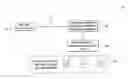
The sole FIGURE is a block diagram of an electronic skylight system according to the present invention.
Similar reference characters denote corresponding features consistently throughout the attached drawings.
DETAILED DESCRIPTION OF THE PREFERRED EMBODIMENTS
As shown in the drawing, the electronic skylight system 10 includes a preferably roof-mounted photovoltaic solar panel 15 electrically connected to one or more ceiling-mounted, high efficiency light sources 35, preferably LEDs, to simulate the light-producing effect of a skylight. In lieu of LEDs, an array of compact fluorescent light sources may provide the illumination.
The output of roof-mounted photovoltaic (PV) panel 15 is routed via a single roof-penetrating 2-conductor cable 17 to a distribution box 20, thereby providing power to a single switched LED array, or a plurality of power switched LED arrays 35, that may be mounted in disparate locations throughout an interior space. Disposed between the PV panel 15 and the distribution box 20 is an optional twelve-volt battery with charge controller and battery protection 25. The PV power source 15 or battery power source 25 activates one or more of the power-switched ceiling-mounted LED light arrays 35. The power-switched LED light arrays 35 allow the user to switch LED light arrays on or off for customized lighting control.
Multiple rooms, i.e., disparate interior spaces, can be illuminated from power provided by one photovoltaic panel 15. The light output per room can be adjusted by using various power levels of LED lights in the arrays 35. The battery backup with charge controller and battery protection 25 may be provided to extend the lighting into the evening hours and on overcast days. A timer shutting on/off the LED arrays 35 may also be included in the distribution box 20.
It is to be understood that the present invention is not limited to the embodiment described above, but encompasses any and all embodiments within the scope of the following claims.
Claims
I claim:1. An electronic skylight system, comprising:
a photovoltaic panel adapted for mounting on an exterior of a structure;
a cable having two conductors electrically connected to the photovoltaic panel, the cable being adapted for penetrating into an interior space of the structure;
a distribution box electrically connected to the cable, the distribution box having an output adapted for routing power to a plurality of interior locations; and
at least one power-switched LED array accepting the output from the distribution box, the array being adapted for mounting on a ceiling of the interior space.
2. An electronic skylight system, comprising:
a photovoltaic panel adapted for mounting on an exterior of a structure;
a cable having two conductors electrically connected to the photovoltaic panel, the cable being adapted for penetrating into an interior space of the structure;
a distribution box electrically connected to the cable, the distribution box having an output adapted for routing power to a plurality of interior locations; and
at least one power-switched electrical light source accepting the output from the distribution box, the electrical light source being adapted for mounting on a ceiling of the interior space.
3. The electronic skylight system according to claim 2, wherein the electrical light source is an array of compact fluorescent lamps.
4. The electronic skylight system according to claim 2, wherein the electrical light source is an array of light emitting diodes.
5. The electronic skylight system according to claim 2, wherein arrays of said electrical light source are mounted in disparate locations throughout the interior space.
6. The electronic skylight system according to claim 5, wherein said arrays have electrical lights having adjustable power levels for adjusting light output in each of the disparate interior spaces.
7. The electronic skylight system according to claim 2, further comprising:
a battery with charge controller and battery protection disposed between the PV panel and the distribution box; and
a switch electrically connecting the battery to the distribution box.
8. The electronic skylight system according to claim 2, further comprising a timer controlling power to the electrical light source, the timer being disposed in said distribution box.
Images & Drawings included:
Sources:
- United States Patent and Trademark Office - verify current appl. status at the USPTO↗
Recent applications in this class:
- » 20240151374 2024-05-09
Self-build solar light kit - » 20230304640 2023-09-28
SOLAR PANEL AND BATTERY WITH SPLITTER FOR DOUBLE ELECTRICAL CABLE OUTPUT THEREFROM - » 20230194060 2023-06-22
Rechargeable string lights - » 20220186896 2022-06-16
CANDLE LAMP CHARGING DEVICE AND CANDLE LAMP - » 20220163175 2022-05-26
Solar string light - » 20220107064 2022-04-07
Hybrid power system for lighting and other uses - » 20220057056 2022-02-24
Portable solar strip lights - » 20210239284 2021-08-05
Solar-powered lighting devices - » 20200340636 2020-10-29
INDUCTIVE POWER SOLAR LIGHT WITH MICROWAVE MOTION SENSOR - » 20200173618 2020-06-04
DECORATIVE SOLAR-POWERED LIGHTING SYSTEM, A DECORATIVE SOLAR MODULE OVERLAY, AND A DECORATIVE SOLAR MODULE ASSEMBLY FOR A DECORATIVE SOLAR-POWERED LIGHTING SYSTEM