Method for reducing sound output at the back of a turbo engine and turbo engine improved by this method
US20100107597A1
2010-05-06
12/532,397
2008-03-17
✅ Patent granted
US 8,607,452 B2
2013-12-17
WO; PCT/FR2008/000348; 20080317
WO; WO2008/129177; 20081030
Gerald L Sung | William Breazeal
Dickinson Wright PLLC
2031-04-13
Abstract:
The invention relates to a method for reducing the noise missions from the rear of a turbo engine, and a turbo engine improved by said method. According to the invention, the nozzle for the cold flow (9) is modified by a transverse expansion and a lengthening thereof such as to be able to increase the length of the acoustic damping coating (14) supported on the inside of said nozzle.
Assignee:
- AIRBUS OPERATIONS (S.A.S.) 2,221 🇫🇷 Toulouse, France
- Airbus Operations 109 🇫🇷 Toulouse, France
Applicant:
Interested in similar patents?
Get notified when new applications in this technology area are published.
Classification:
B21K25/00 IPC
Uniting components to form integral members, e.g. turbine wheels and shafts, caulks with inserts, with or without shaping of the components
F02K1/827 » CPC main
Plants characterised by the form or arrangement of the jet pipe or nozzle; Jet pipes or nozzles peculiar thereto; Other construction of jet pipes; Jet pipe walls, e.g. liners Sound absorbing structures or liners
F02K3/06 » CPC further
Plants including a gas turbine driving a compressor or a ducted fan in which part of the working fluid by-passes the turbine and combustion chamber the plant including ducted fans, i.e. fans with high volume, low pressure outputs, for augmenting the jet thrust, e.g. of double-flow type with front fan
F05D2230/80 » CPC further
Manufacture Repairing, retrofitting or upgrading methods
F05D2250/711 » CPC further
Geometry; Shape curved convex
F05D2250/712 » CPC further
Geometry; Shape curved concave
F05D2250/713 » CPC further
Geometry; Shape curved inflexed
Y10T29/4932 » CPC further
Metal working; Method of mechanical manufacture; Impeller making Turbomachine making
F02K3/02 IPC
Plants including a gas turbine driving a compressor or a ducted fan in which part of the working fluid by-passes the turbine and combustion chamber
F01N1/24 IPC
Silencing apparatus characterised by method of silencing by using sound-absorbing materials
F02K1/00 IPC
Plants characterised by the form or arrangement of the jet pipe or nozzle; Jet pipes or nozzles peculiar thereto
F02K1/82 IPC
Plants characterised by the form or arrangement of the jet pipe or nozzle; Jet pipes or nozzles peculiar thereto; Other construction of jet pipes Jet pipe walls, e.g. liners
Description
The present invention relates to a method for reducing the sound output at the back of an aircraft bypass turbojet engine and to a turbojet engine improved by implementing this method.
It is know that bypass turbojet engines comprise a nacelle defining an air inlet at the front and axially containing a cold stream fan, a central hot stream generator and a fan duct of annular section provided, at the rear, with a jet pipe nozzle for said cold stream, and that, in at least some of these turbojet engines:
-
- said cold stream jet pipe nozzle is formed by an outer fan cowl and by an inner fan cowl of which the initial rear parts are respectively convex and concave and converge toward one another until they meet to form an initial outlet orifice for the cold stream;
- a sound deadening coating of annular section that has to have a preset optimum thickness in order effectively to deaden the noise generated by said fan and carried along in said cold stream, said coating being borne internally by said inner fan cowl at the location where the distance between said converging parts of said inner and outer fan cowls is at least equal to said optimal thickness of the sound deadening coating;
- said hot stream generator is enclosed in an axial engine cowl that has at least approximately the shape of a divergent front conical surface and of a convergent rear conical surface opposing one another on a common base which lies forward of said initial cold stream outlet orifice, the initial jet pipe nozzle throat and the initial cold stream outlet section being delimited between the initial rear part of the inner fan cowl and the rear conical surface of said engine cowl, said rear conical surface comprising, in its rear part, at least one opening which is positioned on the outside with respect to said cold stream initial outlet orifice and which is intended to discharge to the outside a stream of ventilating air bled from said cold stream and introduced into said engine cowl to regulate the temperature of said hot stream generator; and
- said fan duct is delimited between said inner fan duct and said engine cowl.
In a turbojet engine such as this, the rear part of the cold stream jet pipe nozzle may have noise-deadening characteristics that are not optimal because throughout that part of it in which the distance between the converging rear parts of said inner and outer fan cowls is smaller than said optimal thickness of said noise deadening coating, there is no space to house said coating.
It is an object of the present invention to remedy this disadvantage by allowing a greater area of sound deadening coating to be housed between said convergent rear parts of the inner and outer fan cowls.
To this end, according to the invention, starting out from a turbo jet engine initial status, which turbo jet engine comprises inner and outer fan cowl rear parts, a cold stream outlet orifice, a jet pipe nozzle throat and a cold stream outlet section all arranged in the initial way described hereinabove, the method is notable:
-
- in that, without making any modifications to said axial engine cowl:
- said concave initial rear part of the inner fan cowl is modified:
- by progressively diverting it away from the axis of said turbojet engine and lengthening it rearward beyond said initial cold stream outlet orifice,
- then by extending it rearward in the form of a convex rear end part the rear edge of which defines a modified cold stream outlet orifice, the latter orifice being positioned near said opening through which the ventilation air is discharged, but forwards thereof, and
- by shaping said convex rear end part in such a way that it, with said rear conical surface of the axial engine cowl, delimits:
- a modified jet pipe nozzle throat the area of which is equal to that of said initial jet pipe nozzle throat, and
- a modified cold stream outlet section the area of which is equal to that of said initial cold stream outlet section; and
- said convex initial rear part of said outer fan cowl is modified:
- by progressively diverting it away from the axis of said turbojet engine and lengthening it rearward to beyond said initial cold stream outlet orifice,
- then by extending it rearward in the form of a concave rear end part the rear edge of which meets said rear edge of said convex rear end part in order jointly to form said modified cold stream outlet orifice, and
- by shaping said modified convex rear part in such a way that it, with the modified concave rear part of the inner fan cowl, delimits an intermediate space of which the thickness is, just beyond said initial cold stream outlet orifice, at least equal to said optimum thickness for said sound deadening coating, and
- said concave initial rear part of the inner fan cowl is modified:
- in that said sound deadening coating is placed in all of said intermediate space.
- in that, without making any modifications to said axial engine cowl:
Thus, by virtue of such a transverse expansion and such a lengthening of the cold stream jet pipe nozzle it is possible for the axial length (parallel to the axis of said turbojet engine) of the sound deadening coating that can be installed at the periphery of the fan duct to be increased considerably rearward. This then results in excellent reduction in the noise output by the fan at the back of the turbojet engine.
In addition, implementing the method according to the present invention yields the advantageous results that the increase in axial length obtained for the noise deadening coating is greater than the ensuing increase in axial length (distance between the initial and modified cold stream outlet orifices) of the cold stream jet pipe nozzle. Experience has shown that this increase in axial length of the sound deadening coating may be up to 25% greater than the increase in axial length of the cold stream jet pipe nozzle.
It must be pointed out that the modification, according to the present invention, to the convex initial rear part of the outer fan cowl leads to the formation of a zone of inflection where it meets the concave rear end part. The variation in curvature that occurs in this zone of inflection needs not to cause an inversion of the pressure gradient, as this would have the effect of causing boundary layer separation in the rear part of the outer fan cowl. To avoid such a disadvantage, steps are taken to ensure that the shape parameter Hi of the zone of inflection remains lower than 1.6.
Of course, the present invention additionally relates to a turbojet engine that is improved in accordance with the abovementioned method.
The figures of the attached drawing will make it easy to understand how the invention may be embodied. In these figures, identical references denote elements that are similar.
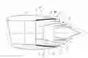
FIG. 1 is a schematic axial section of a bypass turbojet engine.
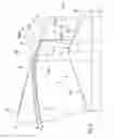
FIG. 2 is a schematic and partial transversely expanded half-section of the rear part of the initial cold stream jet pipe nozzle of the turbojet engine of FIG. 1, the modified rear part being depicted in dotted line.
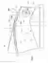
FIG. 3 is a schematic and partial transversely expanded half-section of the rear part of the modified cold stream jet pipe nozzle, said FIG. 3 being comparable with FIG. 2 and the initial rear part being depicted therein in dotted line.
The bypass turbojet engine 1 of longitudinal axis L-L depicted in FIG. 1 comprises a nacelle 2 delimiting an air inlet 3 at the front and axially containing a fan 4 generating the cold stream symbolized by arrows 5, a central generator 6 generating the hot stream symbolized by arrows 7 and an annular-section fan duct 8 provided with a jet pipe nozzle 9 for said cold stream 5.
As also shown, and on a larger scale, in FIG. 2, the cold stream jet pipe nozzle 9 is formed by an outer fan cowl 10 and by an inner fan cowl 11 of which the rear parts 10R and 11R, which are respectively convex and concave, converge toward one another toward the rear to form the cold stream 5 outlet orifice 12.
A noise deadening coating 14, of annular cross section, for example of the known cellular type, is borne internally by the inner fan cowl 11. In order effectively to deaden toward the rear the noise generated by the fan 4 and carried along in the cold stream 5, the sound deadening coating 14 has to have an optimum thickness equal to E. As a result, the sound deadening coating 14 cannot be fitted into the annular rear tip 15 of the nacelle 2, adjacent to the outlet orifice 12 and beginning in the rearward direction at the transverse plane 15P, in which tip the distance between the convergent parts of the cowls 10 and 11 is less than the thickness E.
The hot stream generator 6 is enclosed in an axial engine cowl 16 that has at least approximately the shape of a divergent front conical surface 16A and of a convergent rear conical surface 16R which are opposed to one another on a common base 17 which lies forward of the cold stream 5 outlet orifice 12.
The rear part 11R of the inner fan cowl 11 and the rear conical surface 16R of the engine cowl 16 between them delimit the cold stream 9 jet pipe nozzle throat 18 and the outlet section 19 for said cold stream 5, said throat 18 and said outlet section 19 each being formed by a slightly conical annular surface coaxial with the axis L-L of the turbojet engine 1.
The rear conical surface 16R comprises, to the rear of and on the outside of the cold stream outlet orifice 12, at least one opening 20 (for example in the form of an annular slot) intended to discharge to the outside a ventilation air stream symbolized by the arrows 21 and bled (in a known way that has not been depicted) from the cold stream 5 and introduced into the engine cowl 16 (again in a known way that has not been depicted) in order to regulate the temperature of said hot stream generator 6.
The fan duct 8 is thus delimited between said inner fan cowl 11 (or the sound deadening coating 14) and said engine cowl 16. According to the present invention, in order to be able to increase the length of the sound deadening coating 14, of optimum thickness E, rearward parallel to the axis L-L of the turbojet engine 1 and thus reduce the noise at the rear of said turbojet engine without thereby detracting from engine performance:
-
- no modification is made to the engine cowl 16 of the hot stream generator 6 but, as illustrated by FIG. 2:
- said concave initial rear part 11R of the inner fan cowl 11 is modified:
- by progressively diverting it away from the axis L-L of said turbojet engine and lengthening it rearward beyond said initial cold stream outlet orifice 12 (see dotted line 11RM),
- then by extending it rearward in the form of a convex rear end part 22 the rear edge of which defines a modified cold stream outlet orifice 12M, the latter orifice 12M being positioned near said opening 20 through which the ventilation air is discharged, but forwards thereof, and
- by shaping said convex rear end part 22 in such a way that it, with said rear conical surface 16R of the axial engine cowl 16, delimits:
- a modified jet pipe nozzle throat 18M the area of which is equal to that of said initial jet pipe nozzle throat 18, and
- a modified cold stream outlet section 19M the area of which is equal to that of said initial cold stream outlet section 19; and in addition
- said convex initial rear part 10R of said outer fan cowl 10 is modified:
- by progressively diverting it away from the axis L-L of said turbojet engine and lengthening it rearward to beyond said initial cold stream outlet orifice 12 (see dotted line 10RM),
- then by extending it rearward in the form of a concave rear end part 23 the rear edge of which meets said rear edge of said convex rear end part 22 in order jointly to form said modified cold stream outlet orifice 12M, and
- said modified convex rear part 10RM is shaped in such a way that it, with the modified concave rear part 11RM of the inner fan cowl 11, delimits an intermediate space 24 of which the thickness is, just beyond said initial cold stream outlet orifice 12, at least equal to said optimum thickness E for said sound deadening coating 14, and
- said concave initial rear part 11R of the inner fan cowl 11 is modified:
- said sound deadening coating 14 is placed in all of said intermediate space 24, as far as the plane 24P beyond which, rearward, the thickness of said space becomes smaller than the optimum thickness E for the coating 14 (see also FIG. 3).
- no modification is made to the engine cowl 16 of the hot stream generator 6 but, as illustrated by FIG. 2:
Thus, the sound deadening coating 14 can extend as far as the transverse plane 24P positioned to the rear of the initial cold stream outlet orifice 12.
In FIG. 3, in which the rear part 9RM of the jet pipe nozzle 9, modified as indicated hereinabove, has been depicted in solid line, with the outline of the initial jet pipe nozzle 9 indicated in dotted line, it may be seen that the lengthening ΔL of the axial length of the coating 14 thus obtained exceeds the lengthening Δl of the jet pipe nozzle in the rearward direction.
It will be noted that, where the modified convex part 10RM and the concave rear end part 23 meet, a profile of inflection 25 is formed on the outer fan cowl. This profile of inflection 25 is additionally shaped in such a way as to cause no boundary layer separation. To do this, the shape parameter Hi of the profile of inflection 25 is chosen to be equal to 1.6 at most.
Claims
1-4. (canceled)
5. A method for reducing sound output at the back of an aircraft bypass turbojet engine (1), said method employing modifications to the rear of said turbojet engine (1) and the latter comprising a nacelle (2) defining an air inlet (3) at the front and axially containing a cold stream fan (4), a central hot stream generator (6) and a fan duct (8) of annular section provided, at the rear, with a jet pipe nozzle (9) for said cold stream, in which turbojet engine, in its initial state prior to modification:
said cold stream jet pipe nozzle (9) is formed by an outer fan cowl (10) and by an inner fan cowl (11) of which the initial rear parts (10R, 11R) are respectively convex and concave and converge toward one another until they meet to form an initial outlet orifice (12) for the cold stream (5);
a sound deadening coating (14) of annular section that has to have a preset optimum thickness (E) in order effectively to deaden the noise generated by said fan (4) and carried along in said cold stream (5), said coating (14) being borne internally by said inner fan cowl (11) at the location where the distance between said converging parts of said inner and outer fan cowls is at least equal to said optimal thickness (E) of the sound deadening coating (14);
said hot stream generator (6) is enclosed in an axial engine cowl (16) that has at least approximately the shape of a divergent front conical surface (16A) and of a convergent rear conical surface (16R) opposing one another on a common base (17) which lies forward of said initial cold stream outlet orifice (12), the initial jet pipe nozzle throat (18) and the initial cold stream outlet section (19) being delimited between the initial rear part (11R) of the inner fan cowl (11) and the rear conical surface (16R) of said engine cowl (6),
said rear conical surface (16R) comprising, in its rear part, at least one opening (20) which is positioned on the outside with respect to said cold stream initial outlet orifice (12) and which is intended to discharge to the outside a stream of ventilating air (21) bled from said cold stream (5) and introduced into said engine cowl (16) to regulate the temperature of said hot stream generator (6); and
said fan duct (8) is delimited between said inner fan duct (11) and said engine cowl (16), wherein:
in that, without making any modifications to said axial engine cowl (16):
said concave initial rear part (11R) of the inner fan cowl (11) is modified:
by progressively diverting it away from the axis (L-L) of said turbojet engine and lengthening it rearward beyond said initial cold stream outlet orifice (12),
then by extending it rearward in the form of a convex rear end part (22) the rear edge of which defines a modified cold stream outlet orifice (12M), the latter orifice (12M) being positioned near said opening (20) through which the ventilation air is discharged, but forwards thereof, and
by shaping said convex rear end part (22) in such a way that it, with said rear conical surface (16R) of the axial engine cowl (16), delimits:
a modified jet pipe nozzle throat (18M) the area of which is equal to that of said initial jet pipe nozzle throat (18), and a modified cold stream outlet section (19M) the area of which is equal to that of said initial cold stream outlet section (19); and
said convex initial rear part (10R) of said outer fan cowl (10) is modified:
by progressively diverting it away from the axis of said turbojet engine and lengthening it rearward to beyond said initial cold stream outlet orifice (12),
then by extending it rearward in the form of a concave rear end part (23) the rear edge of which meets said rear edge of said convex rear end part (22) in order jointly to form said modified cold stream outlet orifice (12M), and
by shaping said modified convex rear part (10RM) in such a way that it, with the modified concave rear part (11RM) of the inner fan cowl, delimits an intermediate space (24) of which the thickness is, just beyond said initial cold stream outlet orifice (12), at least equal to said optimum thickness (E) for said sound deadening coating (14), and
in that said sound deadening coating (14) is placed in all of said intermediate space (24).
6. The method as claimed in claim 1, wherein the profile of inflection (25) formed between the diverted and lengthened convex rear part of said outer fan cowl, and said concave rear end extension part (23) is designed not to generate any boundary layer separation.
7. The method as claimed in claim 2, wherein the shape parameter Hi of said profile of inflection (25) is equal to 1.6 at most.
8. A bypass turbojet engine (1) improved according to the method of claim 1.
Images & Drawings included:
Sources:
- United States Patent and Trademark Office - verify current appl. status at the USPTO↗
Recent applications in this class:
- » 20250250950 2025-08-07
ACOUSTIC PANEL WITH DIFFERENT CELL CONFIGURATIONS - » 20250035069 2025-01-30
ASSEMBLY FOR AN EXHAUST CONE OF AN AIRCRAFT TURBOMACHINE - » 20250003374 2025-01-02
LOW-FREQUENCY ACOUSTIC CENTER BODY - » 20240280067 2024-08-22
TOOLS AND METHODS FOR FORMING ACOUSTIC CORES - » 20240159203 2024-05-16
Low-frequency acoustic center body - » 20240159202 2024-05-16
Zoned liner exhaust with buried N-core - » 20230287847 2023-09-14
METHODS AND APPARATUSES FOR REDUCING ENGINE NOISE - » 20230175458 2023-06-08
MULTI-CORE ACOUSTIC PANEL FOR AN AIRCRAFT PROPULSION SYSTEM - » 20230079348 2023-03-16
Low-frequency acoustic center body - » 20230003176 2023-01-05
Method for manufacturing a structure with cellular cores for a turbojet nacelle
Recent applications for this Assignee:
- » 20250201879 2025-06-19
Soft-Start Strategy Of A Fuel Cell - » 20250196988 2025-06-19
DEVICE FOR ABSORBING ENERGY BY COMPRESSION, AIRCRAFT COMPRISING AT LEAST ONE SUCH DEVICE - » 20250136265 2025-05-01
AIRCRAFT CARGO DOOR ACTUATION SYSTEM - » 20250136264 2025-05-01
AIRCRAFT CARGO DOOR ACTUATION SYSTEM - » 20250115365 2025-04-10
AIRCRAFT COMPRISING AT LEAST ONE ENGINE ATTACHMENT SYSTEM THAT HAS REDUCED VERTICAL BULK - » 20250078670 2025-03-06
METHOD FOR MANAGING TAXIING PATHS - » 20250076893 2025-03-06
METHOD AND DEVICE FOR OPTIMIZING A CLIMB PHASE OF AN AIRCRAFT, IN PARTICULAR IN TERMS OF FUEL CONSUMPTION - » 20250074608 2025-03-06
AIRCRAFT PYLON FAIRING, FAIRING ASSEMBLY, AIRCRAFT PYLON AND AIRCRAFT - » 20250074574 2025-03-06
AIRCRAFT FUSELAGE - » 20250042565 2025-02-06
AIRCRAFT AIR INTAKE COMPRISING AN OUTER WALL AND FRONT AND REAR FRAMES LINKED BY AT LEAST ONE JOINING ELEMENT DISTINCT FROM THE OUTER WALL