Method for assembling jointed wind turbine blade
US20100132884A1
2010-06-03
12/474,261
2009-05-28
✅ Patent granted
US 7,998,303 B2
2011-08-16
-
-
Philip C Tucker | Brian R Slawski
2029-12-31
Abstract:
A method of assembling a wind turbine blade comprises providing a first blade segment comprising at least two first spar cap segments; providing a second blade segment comprising at least two second spar cap segments; inserting the second blade segment into the first blade segment wherein a spar cap cavity is formed between each set of corresponding first and second spar cap segments; injecting an adhesive into the spar cap cavities to bond the blade segments together, wherein a scarf joint is formed between each set of corresponding first and second spar cap segments.
Inventors:
- Wendy Wen-Ling Lin 41 🇺🇸 Niskayuna, NY, United States
- Chandra Sekher Yerramalli 12 🇺🇸 Niskayuna, NY, United States
- Thomas Miebach 15 🇺🇸 Ballston Spa, NY, United States
- Peggy Lynn Baehmann 27 🇺🇸 Glenville, NY, United States
- Shu Ching Quek 21 🇺🇸 Clifton Park, NY, United States
- Eric John Telfeyan 2 🇺🇸 Guilderland, NY, United States
- Chandra Sekher Yerramalli 1 🇺🇸 Nishayuna, NY, United States
Assignee:
- GENERAL ELECTRIC COMPANY 28,775 🇺🇸 Schenectady, NY, United States
- GENERAL ELECTRIC COMPANY 3,939 🇺🇸 Niskayuna, NY, United States
Interested in similar patents?
Get notified when new applications in this technology area are published.
Classification:
B29C65/00 » CPC further
Joining of preformed parts ; Apparatus therefor
B29C66/1122 » CPC main
General aspects of processes or apparatus for joining preformed parts; General aspects dealing with the joint area or with the area to be joined; Particular design of joint configurations particular design of the joint cross-sections; Joint cross-sections comprising a single joint-segment, i.e. one of the parts to be joined comprising a single joint-segment in the joint cross-section; Single lapped joints Single lap to lap joints, i.e. overlap joints
B29C65/542 » CPC further
Joining of preformed parts ; Apparatus therefor using adhesives, i.e. using supplementary joining material; solvent bonding applying the adhesive between pre-assembled parts by injection
B29C66/1142 » CPC further
General aspects of processes or apparatus for joining preformed parts; General aspects dealing with the joint area or with the area to be joined; Particular design of joint configurations particular design of the joint cross-sections; Joint cross-sections comprising a single joint-segment, i.e. one of the parts to be joined comprising a single joint-segment in the joint cross-section; Single butt joints Single butt to butt joints
B29C66/54 » CPC further
General aspects of processes or apparatus for joining preformed parts; General aspects of joining tubular articles; General aspects of joining long products, i.e. bars or profiled elements; General aspects of joining single elements to tubular articles, hollow articles or bars; General aspects of joining several hollow-preforms to form hollow or tubular articles; Joining tubular articles, profiled elements or bars; Joining single elements to tubular articles, hollow articles or bars; Joining several hollow-preforms to form hollow or tubular articles Joining several hollow-preforms, e.g. half-shells, to form hollow articles, e.g. for making balls, containers; Joining several hollow-preforms, e.g. half-cylinders, to form tubular articles
B29C66/543 » CPC further
General aspects of processes or apparatus for joining preformed parts; General aspects of joining tubular articles; General aspects of joining long products, i.e. bars or profiled elements; General aspects of joining single elements to tubular articles, hollow articles or bars; General aspects of joining several hollow-preforms to form hollow or tubular articles; Joining tubular articles, profiled elements or bars; Joining single elements to tubular articles, hollow articles or bars; Joining several hollow-preforms to form hollow or tubular articles; Joining several hollow-preforms, e.g. half-shells, to form hollow articles, e.g. for making balls, containers; Joining several hollow-preforms, e.g. half-cylinders, to form tubular articles joining more than two hollow-preforms to form said hollow articles
B29C66/721 » CPC further
General aspects of processes or apparatus for joining preformed parts characterised by the composition, physical properties or the structure of the material of the parts to be joined; Joining with non-plastics material characterised by the structure of the material of the parts to be joined Fibre-reinforced materials
B29C66/723 » CPC further
General aspects of processes or apparatus for joining preformed parts characterised by the composition, physical properties or the structure of the material of the parts to be joined; Joining with non-plastics material characterised by the structure of the material of the parts to be joined being multi-layered
F03D1/0675 » CPC further
Wind motors with rotation axis substantially parallel to the air flow entering the rotor ; Rotors characterised by their construction, i.e. structural design details of the blades
B29C65/483 » CPC further
Joining of preformed parts ; Apparatus therefor using adhesives, i.e. using supplementary joining material; solvent bonding characterised by the type of adhesives Reactive adhesives, e.g. chemically curing adhesives
B29C66/72323 » CPC further
General aspects of processes or apparatus for joining preformed parts characterised by the composition, physical properties or the structure of the material of the parts to be joined; Joining with non-plastics material characterised by the structure of the material of the parts to be joined being multi-layered comprising a non-plastics layer consisting of elements other than metals, e.g. boron Carbon
B29C66/72326 » CPC further
General aspects of processes or apparatus for joining preformed parts characterised by the composition, physical properties or the structure of the material of the parts to be joined; Joining with non-plastics material characterised by the structure of the material of the parts to be joined being multi-layered comprising a non-plastics layer consisting of inorganic materials not provided for in - Glass
B29C66/72329 » CPC further
General aspects of processes or apparatus for joining preformed parts characterised by the composition, physical properties or the structure of the material of the parts to be joined; Joining with non-plastics material characterised by the structure of the material of the parts to be joined being multi-layered comprising a non-plastics layer consisting of natural products or their composites, not provided for in - Wood
B29C66/727 » CPC further
General aspects of processes or apparatus for joining preformed parts characterised by the composition, physical properties or the structure of the material of the parts to be joined; Joining with non-plastics material characterised by the structure of the material of the parts to be joined being porous, e.g. foam
B29K2105/04 » CPC further
Condition, form or state of moulded material or of the material to be shaped cellular or porous
B29K2105/06 » CPC further
Condition, form or state of moulded material or of the material to be shaped containing reinforcements, fillers or inserts
B29K2307/00 » CPC further
Use of elements other than metals as reinforcement
B29L2009/00 » CPC further
Layered products
B29L2031/082 » CPC further
Other particular articles; Blades for rotors, stators, fans, turbines or the like, e.g. screw propellers Blades, e.g. for helicopters
B29L2031/085 » CPC further
Other particular articles; Blades for rotors, stators, fans, turbines or the like, e.g. screw propellers; Blades, e.g. for helicopters Wind turbine blades
B29L2031/7504 » CPC further
Other particular articles; Machines or parts thereof not otherwise provided for Turbines
F05B2240/302 » CPC further
Components; Rotors; Characteristics of rotor blades, i.e. of any element transforming dynamic fluid energy to or from rotational energy and being attached to a rotor Segmented or sectional blades
Y02E10/72 » CPC further
Energy generation through renewable energy sources; Wind energy Wind turbines with rotation axis in wind direction
Y02E10/72 » CPC further
Energy generation through renewable energy sources; Wind energy Wind turbines with rotation axis in wind direction
Y02P70/50 » CPC further
Climate change mitigation technologies in the production process for final industrial or consumer products Manufacturing or production processes characterised by the final manufactured product
Y02P70/50 » CPC further
Climate change mitigation technologies in the production process for final industrial or consumer products Manufacturing or production processes characterised by the final manufactured product
Y10T29/49336 » CPC further
Metal working; Method of mechanical manufacture; Impeller making Blade making
B29C66/114 » CPC further
General aspects of processes or apparatus for joining preformed parts; General aspects dealing with the joint area or with the area to be joined; Particular design of joint configurations particular design of the joint cross-sections; Joint cross-sections comprising a single joint-segment, i.e. one of the parts to be joined comprising a single joint-segment in the joint cross-section Single butt joints
B29C66/116 » CPC further
General aspects of processes or apparatus for joining preformed parts; General aspects dealing with the joint area or with the area to be joined; Particular design of joint configurations particular design of the joint cross-sections; Joint cross-sections comprising a single joint-segment, i.e. one of the parts to be joined comprising a single joint-segment in the joint cross-section Single bevelled joints, i.e. one of the parts to be joined being bevelled in the joint area
B29K2307/04 » CPC further
Use of elements other than metals as reinforcement Carbon
B29C66/7212 » CPC further
General aspects of processes or apparatus for joining preformed parts characterised by the composition, physical properties or the structure of the material of the parts to be joined; Joining with non-plastics material characterised by the structure of the material of the parts to be joined; Fibre-reinforced materials characterised by the composition of the fibres
B29K2309/08 » CPC further
Use of inorganic materials not provided for in groups - , as reinforcement Glass
B32B37/12 IPC
Methods or apparatus for laminating, e.g. by curing or by ultrasonic bonding characterised by using adhesives
B29C65/54 IPC
Joining of preformed parts ; Apparatus therefor using adhesives, i.e. using supplementary joining material; solvent bonding applying the adhesive between pre-assembled parts
B32B37/00 IPC
Methods or apparatus for making layered products; Treatment of the layers or of the layered products
B32B37/00 IPC
Methods or apparatus for laminating, e.g. by curing or by ultrasonic bonding
C09J5/00 IPC
Adhesive processes in general; Adhesive processes not provided for elsewhere, e.g. relating to primers
B63H1/26 IPC
Propulsive elements directly acting on water of rotary type with rotation axis substantially in propulsive direction; Propellers Blades
B63H1/06 IPC
Propulsive elements directly acting on water of rotary type with rotation axis substantially at right angles to propulsive direction with adjustable vanes or blades
B63H5/125 IPC
Arrangements on vessels of propulsion elements directly acting on water of propellers movably mounted with respect to hull, e.g. adjustable in direction, e.g. podded azimuthing thrusters
B64C11/16 IPC
Propellers, e.g. of ducted type; Features common to propellers and rotors for rotorcraft Blades
B64C27/46 IPC
Rotorcraft; Rotors peculiar thereto; Rotors Blades
B64C11/12 IPC
Propellers, e.g. of ducted type; Features common to propellers and rotors for rotorcraft; Hub construction; Blade mountings for non-adjustable blades flexible
F01D5/14 IPC
Blades; Blade-carrying members ; Heating, heat-insulating, cooling or antivibration means on the blades or the members; Blades Form or construction
F03B7/00 IPC
Water wheels
F04D29/38 IPC
Details, component parts, or accessories; Rotors specially for elastic fluids for axial flow pumps Blades
B63H7/02 IPC
Propulsion directly actuated on air using propellers
Description
FIELD OF THE INVENTION
This disclosure relates to a wind turbine blade and methods of assembly thereof.
BACKGROUND OF THE INVENTION
The subject matter disclosed herein relates generally to wind turbine blades, and more particularly, to a multi-segment wind turbine blade with at least two blade segments and a method of assembling the at least two blade segments.
Transporting lengthy wind turbine blades to a field site incurs significant costs. As the capacity of wind turbines increases, the lengths of the wind turbine blades also increase, further adding to difficulties and costs of transportation. Therefore, there is a need for a wind turbine blade comprising multiple blade segments and a method of assembling the blade segments. The blade segments can be transported to the field site at lower costs and assembled to form the wind turbine blade.
BRIEF SUMMARY OF THE INVENTION
In accordance with one embodiment disclosed herein, a method of assembling a wind turbine blade comprises providing a first blade segment comprising at least two first spar cap segments; providing a second blade segment comprising at least two second spar cap segments; inserting the second blade segment into the first blade segment wherein a spar cap cavity is formed between each set of corresponding first and second spar cap segments; injecting an adhesive into the spar cap cavities to bond the blade segments together, wherein a scarf joint is formed between each set of corresponding first and second spar cap segments.
In accordance with another embodiment disclosed herein, a kit for assembly of a wind turbine blade comprises a first blade segment comprising at least two first spar cap segments; a second blade segment comprising at least two second spar cap segments, wherein the second blade segment can be inserted into the first blade segment to form a spar cap cavity and a scarf joint between each set of corresponding first and second spar cap segments; and an adhesive for filling the spar cap cavities and bonding the first blade segment to the second blade segment.
BRIEF DESCRIPTION OF THE DRAWINGS
These and other features, aspects, and advantages of the present invention will become better understood when the following detailed description is read with reference to the accompanying drawings in which like characters represent like parts throughout the drawings, wherein:
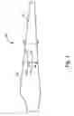
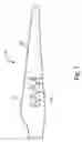
FIG. 1 illustrates a wind turbine blade in accordance with aspects disclosed herein.
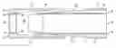
FIG. 2 illustrates a sectional view taken along line 2-2 in FIG. 1, in accordance with aspects disclosed herein.
FIG. 3 is a sectional view taken along line 3-3 in FIG. 1 and illustrates a second blade segment being inserted into first blade segment in accordance with aspects disclosed herein.
FIG. 4 is a sectional view taken along line 3-3 in FIG. 1 and illustrates a second blade segment fully inserted into a first blade segment in accordance with aspects disclosed herein:
FIG. 5 is a sectional view taken along line 4-4 in FIG. 1 and illustrates sealing clips and sealing pads located on the blade segments in accordance with aspects disclosed herein.
FIG. 6 is a sectional view taken along line 6-6 in FIG. 1 and illustrates a skin joint between the blade segments.
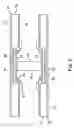
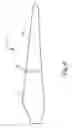
FIG. 7 illustrates a wind turbine blade comprising scar cap injection accordance with aspects disclosed herein.
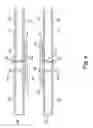
FIG. 8 illustrates a wind turbine blade comprising skin joint injection accordance with aspects disclosed herein.
DETAILED DESCRIPTION OF THE INVENTION
Embodiments disclosed herein include methods of assembling a jointed wind turbine blade. The methods allow transport of blade components to a secondary site or field site where the components can be assembled to form the turbine blade. Referring to FIGS. 1, 2 and 3, a wind turbine blade 10 includes a first blade segment 12 and a second blade segment 14. The first and second blade segments 12 and 14 are each hollow segments comprising an outer skin 18, skin core 20, and inner skin 22. The outer skin 18, skin core 20, and inner skin 22 are made from materials that are light-weight and strong.
The first blade segment 12 includes at least two first spar cap segments 26, and the second blade segment 14 includes at least two second spar cap segments 28. The first and second spar cap segments are configured to form a scarf joint therebetween. A shear web 32 connects the first spar cap segments 26 in the first blade segment 12. Similarly, a shear web 32 connects the second spar cap segments 28 in the second blade segment 14. The spar cap segments bear longitudinal-loads experienced by the wind turbine blades and are attached to the inner skin 22 of the respective blade segments. In one embodiment, the outer skin 18 and spar cap segments 26 and 28 are comprised of composite glass or carbon, and the skin core 20 and shear web 32 are comprised of foam or balsa.
As illustrated in FIGS. 3 and 4, the second blade segment 14 is inserted into the first blade segment 12 wherein a spar cap cavity 36 and scarf joint 38 are formed between each corresponding set of first and second spar cap segments 26 and 28. Prior to joining the first and second blade segments 12 and 14, at least one sealing pad 40 is attached to the first blade segment, wherein the sealing pad is located adjacent to a first spar cap segment 26. The inner skin 22 or the second blade segment 14 abuts against the sealing pad 40 when the second blade segment is inserted into the first blade segment 12, thereby sealing an interior surface of the spar cap cavity 36.
Referring to FIG. 5, at least one sealing clip 42 is attached to the inner skin 22 of the first blade segment 12, and at least one sealing clip pad 44 is attached to the inner skin of the second blade segment 14. The sealing clip 42 will abut against a corresponding sealing clip pad 44, when the second blade segment 14 is inserted into the first blade segment 22, thereby sealing an interior surface of the spar cap cavity. The configuration of the sealing clip 42 and the sealing clip pad 44 can be modified, as long as the sealing clip engages that sealing clip pad to form a tight seal.
In one embodiment, a joint also exists in the shear web 32. For example, a butt joint may exist in the shear web 32 wherein a shear web doubler plate 48 is located on each side of the shear web. The shear web joint can have an alternate configuration, such as a scarf joint. The shear web doubler plates 48 are attached to the second blade segment 14 before joining the first and second blade segments together, as illustrated in FIG. 3 (only one shear web doubler plate 48 is shown). A shear web sealing pad 50 is attached to the first blade segment 12. When the second blade segment 14 is inserted into the first blade segment 12, the shear web doubler plates 48 abut against the shear web sealing pad 50, thereby positioning any free edges of the shear web doubler plates 48 against the shear web sealing pad 50. A shear web joint cavity (not shown) is formed between the shear web doubler plates 48.
After the blade segments are positioned together, a skin joint 52 is formed between the outer skin 18, skin core 20, and inner skin 22 of the first blade 12 segment and the second blade segment 14, as illustrated in FIG. 4. In a preferred embodiment, the skin joint 52 is sealed with a skin joint seal 56 prior to injecting adhesive into the spar cap cavity 36. The skin joint 52 is sealed by any method known to those having skill in the art. In one embodiment, the skin joint seal 56 comprises foam or tape. Referring to FIG. 6, at least one skin joint doubler plate 60 can be attached to the inner skin 22 of the second blade segment 14 with a doubler plate adhesive 61. At least one doubler plate sealing pad 62 is attached to the inner skin 22 of the first blade segment 12. When the second blade segment 14 is inserted into the first blade segment 12, each skin joint doubler plate 60 abuts against a corresponding doubler plate sealing pad 62, wherein a skin joint cavity 64 is formed.
The sealing pads 40, 44, 50, 56 and 62 can be attached to the appropriate blade segment 12 and 14 by any method known to those having skill in the art. In one embodiment, the sealing pads are bonded to the blade segment with an adhesive. In a preferred embodiment, the sealing pads are comprised of foam, although other materials can be used that are suitable for forming a seal.
An adhesive is injected into the spar cap cavity 36, shear web joint cavity, skin joint 52 and skin joint cavity 64, after the second blade segment 12 is inserted into the first blade segment. As shown in FIG. 7, the adhesive is injected into the spar cap cavity 36 through spar cap injection ports 66 located in the first blade segment 12. The bonding of each first spar cap segment 26 to a second spar cap segment 28 forms a scarf joint between the first and second spar cap segments. In one embodiment, the injection of the adhesive begins at one end of the spar cap cavity 36 as illustrated in FIG. 7, and proceeds to the other end of the spar cap cavity until it is filled. The inner skin 22 and spar cap 28 of the second blade segment 14 may be stiffened to resist the adhesive injection pressure by using extra material in the inner skin and/or by using gussets along the length of the spar cap cavity 36. The skin joint cavity 64 is filled with adhesive through skin joint injection ports 68, as illustrated in FIG. 8. The shear web joint cavity, defined by shear web doubler plates 48, is filled with adhesive through shear web injection ports 70 (see FIG. 4). The injection ports 66, 68, and 70 also act as vents during the adhesive injection process.
In one embodiment, the adhesive comprises materials such as epoxies; urethanes, including polyurethane; cyclopentadienes, including dicyclopentadiene; methylmethacrylates; vinylesters; or polyesters. If necessary, the adhesive can be cured following the injection process using any curing method known to those having skill in the art.
All ranges disclosed herein are inclusive of the endpoints, and the endpoints are combinable with each other. The terms “first,” “second,” and the like as used herein do not denote any order, quantity, or importance, but rather are used to distinguish one element from another. The modifiers “about” and “approximately” used in connection with a quantity are inclusive of the stated value and have the meaning dictated by the context (e.g., includes the degree of error associated with measurement of the particular quantity). The use of the terms “a” and “an” and “the” and similar referents in the context of describing the invention (especially in the context of the following claims) are to be construed to cover both the singular and the plural, unless otherwise indicated herein or clearly contradicted by context.
While the invention has been described in detail in connection with a number of embodiments, the invention is not limited to such disclosed embodiments. Rather, the invention can be modified to incorporate any number of variations, alterations, substitutions or equivalent arrangements not heretofore described, but which are commensurate with the spirit and scope of the invention. Additionally, while various embodiments of the invention have been described, it is to be understood that aspects of the invention may include only some of the described embodiments. Accordingly, the invention is not to be seen as limited by the foregoing description, but is only limited by the scope of the appended claims.
Claims
What is claimed is:1. A method of assembling a wind turbine blade, comprising:
providing a first blade segment comprising at least two first spar cap segments;
providing a second blade segment comprising at least two second spar cap segments;
inserting the second blade segment into the first blade segment wherein a spar cap cavity is formed between each set of corresponding first and second spar cap segments;
injecting an adhesive into the spar cap cavities to bond the blade segments together, wherein a scarf joint is formed between each set of corresponding first and second spar cap segments.
2. The method of claim 1, further comprising:
curing the adhesive.
3. The method of claim 1, further comprising:
attaching at least one sealing pad to the first blade segment prior to inserting the first blade segment, wherein the sealing pad is attached adjacent to a first spar cap segment; and
wherein an inner skin of the second blade segment abuts against the sealing pad when the second blade segment is inserted into the first blade segment, thereby sealing an interior surface of the spar cap cavity.
4. The method of claim 1, wherein the first and second blade segments each comprise an outer skin, skin core, and inner skin and wherein a skin joint is formed between the first blade segment skin and the second blade segment skin when the first blade is inserted into the second blade, and the method further comprises:
sealing the skin joint.
5. The method of claim 4, wherein the skin joint is sealed by attaching foam or tape to the joint.
6. The method of claim 1, further comprising:
attaching at least one sealing clip to an inner skin of the first blade segment; and
attaching at least one sealing clip pad to an inner skin of the second blade segment;
wherein the at least one sealing clip abuts against a corresponding sealing clip pad when the second blade segment is inserted into the first blade segment, thereby sealing an interior surface of the spar cap cavity.
7. The method of claim 6, wherein the sealing clip pad is comprised of foam.
8. The method of claim 1, further comprising:
attaching at least one shear web doubler plate to the second blade segment; and
attaching at least one shear web sealing pad to the first blade segment;
wherein the at least one shear web doubler plate abuts against a shear web sealing pad when the second blade segment is inserted into the first blade segment.
9. The method of claim 1, wherein the adhesive is injected into the spar cap cavities through at least one spar cap injection port located in the first blade segment.
10. The method of claim 1, further comprising:
attaching at least one skin joint doubler plate to an inner skin of the second blade segment; and
attaching at least one doubler plate sealing pad to an inner skin of the first blade segment;
wherein the at least one skin joint doubler plate abuts against a doubler plate sealing pad when the second blade segment is inserted into the first blade segment to form a skin joint cavity.
11. The method of claim 10, further comprising:
injecting an adhesive into the skin joint cavity.
12. The method of claim 1, wherein the adhesive comprises a material selected from the group consisting of epoxies, urethanes, cyclopentadienes, methylmethacrylates, vinylesters, and polyesters.
13. A kit for assembly of a wind turbine blade, comprising:
a first blade segment comprising at least two first spar cap segments;
a second blade segment comprising at least two second spar cap segments, wherein the second blade segment can be inserted into the first blade segment to form a spar cap cavity and a scarf joint between each set of corresponding first and second spar cap segments; and
an adhesive for filling the spar cap cavities and bonding the first blade segment to the second blade segment.
14. The kit of claim 13, further comprising:
at least one sealing pad attached to the first blade segment and located adjacent to each first spar cap segment.
15. The kit of claim 13, further comprising:
at least one sealing clip attached to an inner skin of the first blade segment; and
at least one sealing clip pad attached to an inner skin of the second blade segment;
wherein the at least one sealing clip abuts against a corresponding sealing clip pad when the second blade segment is inserted into the first blade segment.
16. The kit of claim 15, wherein the sealing pad is comprised of foam.
17. The kit of claim 13, further comprising:
at least one shear web doubler plate attached to the second blade segment; and
at least one shear web sealing pad attached to the first blade segment;
wherein the at least one shear web doubler plate abuts against a shear web sealing pad when the second blade segment is inserted into the first blade segment.
18. The kit of claim 13, further comprising:
at least one spar cap injection port located in the first blade segment.
19. The kit of claim 13, further comprising
at least one skin joint doubler plate attached to an inner skin of the second blade segment; and
at least one doubler plate sealing pad attached to an inner skin of the first blade segment;
wherein the at least one skin joint doubler plate abuts against a doubler plate sealing pad when the second blade segment is inserted into the first blade segment to form a skin joint cavity.
20. The kit of claim 13, wherein the adhesive comprises a material selected from the group consisting of epoxies, urethanes, cyclopentadienes, methylmethacrylates, vinylesters, and polyesters.
Images & Drawings included:


Sources:
- United States Patent and Trademark Office - verify current appl. status at the USPTO↗
Similar patent applications:
Recent applications in this class:
- » 20250178289 2025-06-05
RELATING TO THE SEALING OF PIPE LINERS - » 20230173765 2023-06-08
Device for providing a tubular foil - » 20230150209 2023-05-18
METHOD FOR PRODUCING WASHABLE ABSORBENT GARMENTS - » 20230077208 2023-03-09
Method for the inspection of bonding patterns of packages for products - » 20220126524 2022-04-28
Temperature control apparatus and temperature control method - » 20210331426 2021-10-28
Method for forming a tube and a method and a packaging machine for forming a package - » 20210206118 2021-07-08
Method for measuring overlaps in prepreg materials - » 20210078261 2021-03-18
Heat sealing apparatus - » 20200316874 2020-10-08
Method of forming a package gusset - » 20200307118 2020-10-01
Foldable inflatable structure
Recent applications for this Assignee:
- » 20250250942 2025-08-07
Overall Engine Efficiency Rating for Turbomachine Engines - » 20250243827 2025-07-31
MULTIPLE-FLOW AIRCRAFT TURBINE ENGINE - » 20250229333 2025-07-17
SYSTEMS AND METHODS FOR SMOOTHING A CONTOUR OF AN OBJECT FORMED DURING ADDITIVE MANUFACTURING - » 20250224115 2025-07-10
TURBINE ENGINE HAVING A COMBUSTION SECTION WITH A FUEL SUPPLY ASSEMBLY - » 20250223929 2025-07-10
UNDUCTED PROPELLER GAS TURBINE COMPRISING A COOLING AIR CHANNEL AND A VARIABLE BLEED VALVE EJECTION CHANNEL - » 20250222519 2025-07-10
ADDITIVE MANUFACTURING SUPPORTS AND METHODS FOR USING SAME IN ADDITIVELY MANUFACTURING PARTS - » 20250215830 2025-07-03
SUSPENSION OF A TRIPLE-FLOW AIRCRAFT TURBINE ENGINE - » 20250215826 2025-07-03
GAS TURBINE ENGINE - » 20250215811 2025-07-03
SYSTEMS AND METHODS FOR ATTACHMENT OF MATERIALS HAVING DIFFERENT THERMAL EXPANSION COEFFICIENTS - » 20250207534 2025-06-26
GAS TURBINE ENGINES AND EPICYCLIC GEARBOXES WITH PLANET GEAR CLEARANCES