Method and RF transmitter arrangement for generating RF fields
US20100141259A1
2010-06-10
12/598,451
2008-04-24
✅ Patent granted
US 8,390,288 B2
2013-03-05
WO; PCT/IB2008/051590; 20080424
WO; WO2008/135883; 20081113
Louis Arana
2029-10-05
Abstract:
A multi-channel RF transmitter arrangement comprising a plurality of RF transmitter elements (e) like RF antennas, antenna elements, coils or coil elements, for generating an RF field, especially for use in a magnetic resonance imaging (MRI) system for exciting nuclear magnetic resonances (NMR), and a method for generating such an RF field is disclosed. The RF transmitter elements (e) are segmented in a plurality of segments (s1, s2, s3, . . . ) at least along the direction of the main magnetic field of the MRI system (or the z-direction or the longitudinal direction.
Inventors:
- Peter Boernert 68 🇩🇪 Hamburg, Germany
- Ulrich Katscher 29 🇩🇪 Norderstedt, Germany
- Ingmar Graesslin 30 🇩🇪 Boenningstedt, Germany
- Peter Vernickel 48 🇩🇪 Hamburg, Germany
Assignee:
- Koninklijke Philips Electronics, N.V. 13,903 🇳🇱 Eindhoven, Netherlands
Applicant:
Interested in similar patents?
Get notified when new applications in this technology area are published.
Classification:
G01V3/00 IPC
Electric or magnetic prospecting or detecting; Measuring magnetic field characteristics of the earth, e.g. declination, deviation
G01R33/34046 » CPC main
Arrangements or instruments for measuring magnetic variables involving magnetic resonance; Details of apparatus provided for in groups - ; Excitation or detection systems, e.g. using radio frequency signals; Constructional details, e.g. resonators, specially adapted to MR Volume type coils, e.g. bird-cage coils; Quadrature bird-cage coils; Circularly polarised coils
G01R33/288 » CPC further
Arrangements or instruments for measuring magnetic variables involving magnetic resonance; Details of apparatus provided for in groups - Provisions within MR facilities for enhancing safety during MR, e.g. reduction of the specific absorption rate [SAR], detection of ferromagnetic objects in the scanner room
G01R33/3415 » CPC further
Arrangements or instruments for measuring magnetic variables involving magnetic resonance; Details of apparatus provided for in groups - ; Excitation or detection systems, e.g. using radio frequency signals; Constructional details, e.g. resonators, specially adapted to MR comprising surface coils comprising arrays of sub-coils, i.e. phased-array coils with flexible receiver channels
G01R33/5659 » CPC further
Arrangements or instruments for measuring magnetic variables involving magnetic resonance using nuclear magnetic resonance [NMR]; NMR imaging systems; Signal processing systems, e.g. using pulse sequences ; Generation or control of pulse sequences; Operator console; Image enhancement or correction, e.g. subtraction or averaging techniques, e.g. improvement of signal-to-noise ratio and resolution; Correction of image distortions, e.g. due to magnetic field inhomogeneities caused by a distortion of the RF magnetic field, e.g. spatial inhomogeneities of the RF magnetic field
G01R33/543 » CPC further
Arrangements or instruments for measuring magnetic variables involving magnetic resonance using nuclear magnetic resonance [NMR]; NMR imaging systems; Signal processing systems, e.g. using pulse sequences ; Generation or control of pulse sequences; Operator console Control of the operation of the MR system, e.g. setting of acquisition parameters prior to or during MR data acquisition, dynamic shimming, use of one or more scout images for scan plane prescription
G01R33/5604 » CPC further
Arrangements or instruments for measuring magnetic variables involving magnetic resonance using nuclear magnetic resonance [NMR]; NMR imaging systems; Signal processing systems, e.g. using pulse sequences ; Generation or control of pulse sequences; Operator console; Image enhancement or correction, e.g. subtraction or averaging techniques, e.g. improvement of signal-to-noise ratio and resolution Microscopy; Zooming
G01R33/5611 » CPC further
Arrangements or instruments for measuring magnetic variables involving magnetic resonance using nuclear magnetic resonance [NMR]; NMR imaging systems; Signal processing systems, e.g. using pulse sequences ; Generation or control of pulse sequences; Operator console; Image enhancement or correction, e.g. subtraction or averaging techniques, e.g. improvement of signal-to-noise ratio and resolution by reduction of the scanning time, i.e. fast acquiring systems, e.g. using echo-planar pulse sequences Parallel magnetic resonance imaging, e.g. sensitivity encoding [SENSE], simultaneous acquisition of spatial harmonics [SMASH], unaliasing by Fourier encoding of the overlaps using the temporal dimension [UNFOLD], k-t-broad-use linear acquisition speed-up technique [k-t-BLAST], k-t-SENSE
G01R33/44 IPC
Arrangements or instruments for measuring magnetic variables involving magnetic resonance using nuclear magnetic resonance [NMR]
Description
FIELD OF INVENTION
The invention relates to an RF transmitter arrangement comprising a plurality of RF transmitter elements like RF antennas, antenna elements, coils or coil elements or other resonator elements, for generating an RF field, especially for use in a magnetic resonance imaging (MRI) system for exciting nuclear magnetic resonances (NMR). The invention further relates to a method for generating such an RF field.
Furthermore, the invention relates to a multi-channel RF transmit system comprising a plurality of RF waveform generators and RF amplifiers, for generating RF transmit signals for feeding such a multi-channel RF transmitter arrangement, especially for use as an RF excitation system in an MRI system.
The invention as well relates to an MRI system comprising such a multi-channel RF transmit or excitation system and such a multi-channel RF transmitter arrangement.
BACKGROUND OF THE INVENTION
Conventional MR systems use one RF transmit coil (e.g. a quadrature body coil (QBC)) fed with a single RF signal. Multi-channel transmit systems use coils with N elements that are fed by N independent RF signals which can be varied in phase and amplitude. With these systems, it is possible to improve image homogeneity, which homogeneity often represents a problem at higher RF field strengths due to so called dielectric resonances or wave propagation effects within an examination object. By using multi-dimensional spatially selective RF pulses and other techniques of RF shimming more homogeneous images can be obtained. Furthermore, parallel RF transmission enables many interesting new technical features like the acceleration of RF pulses for local or zoom imaging.
SUMMARY OF THE INVENTION
With increasing field strength, image inhomogeneity problems which are caused by signal intensity variations are increasing. Furthermore, the specific absorption (SAR) rate limits the possible RF duty cycle in order not to violate existing SAR limits and not to compromise patient safety. Finally, there is a need that higher reduction factors for parallel RF transmission can be achieved.
Consequently, one object underlying the invention is to provide an RF transmitter arrangement and a multi-channel RF transmit system which offers an increased flexibility of applying a spatial RF field pattern which for example can be used to correct for susceptibility artifacts that cause inhomogeneities in the RF field.
The object is solved by an RF transmitter arrangement according to claim 1, a multi-channel RF transmit system according to claims 6 and a method for generating an RF field according to claim 8.
This solutions according to the invention are especially advantageous in those MRI systems with higher magnetic field strength, in which the wavelengths of the required RF transmit or excitation signals reach the dimensions of an examination object, so that wave propagation or dielectric resonance effects within the examination object and inhomogeneous RF excitation fields can occur. The impact of these unwanted effects and especially of signal intensity variations during MRI examinations can be compensated effectively and in an easy and cost-effective manner by transmitting spatially selective RF pulses by means of a independently drivable RF transmitter elements of the multi-channel RF transmit system and a multi-channel RF transmitter arrangement according to the invention.
The subclaims disclose advantageous embodiments of invention.
It will be appreciated that features of the invention are susceptible to being combined in any combination without departing from the scope of the invention as defined by the accompanying claims.
Further details, features and advantages of the invention will become apparent from the following description of preferred and exemplary embodiments of the invention, which are given with reference to the drawings.
BRIEF DESCRIPTION OF THE DRAWINGS
FIG. 1 show schematic block diagrams of a multi-channel RF transmit/receive architecture, and
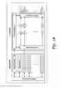
FIG. 2 shows different configurations of coil elements.
DETAILED DESCRIPTION OF EMBODIMENTS
In contrast to existing multi-channel transmit MRI systems and coils, where the individual elements are distributed on the surface of a single cylindrical ring or are arranged along a line forming a planar band, a distribution and/or segmentation of the coils in two or three spatial-directions is provided according to the invention.
One general example of such an RF transmitter arrangement is a planar array of N×M transmitter elements (i.e. arranged in two dimensions) or an array of different rings and/or segments of cylindrically arranged transmitter elements (i.e. arranged in three dimensions).
Although this might increase the number of RF transmit channels required for driving the individual transmitter elements, such an arrangement offers the possibility of reduction of the SAR (specific absorption rate) in particular in cases where only a small volume needs to be excited by means of the RF field, and further offers better performance and flexibility for RF shimming methods (see Ibrahim et al, “Effect of RF coil excitation on field inhomogeneity at ultra high fields: a field optimized TEM resonator” in Magnetic Resonance Imaging (2001) December; 19(10): 1339-47).
Furthermore, it enables the possibility to accelerate and/or improve the performance of multi-dimensional spatially selective RF pulses, as the number of coil or transmitter elements is increased. Especially three-dimensional RF pulses benefit from this increased degree of freedom in coil design for RF transmitter arrangements, which are extended into two or three dimensions.
Another advantage is the reduction of the required power for each transmit channel for feeding the RF transmitter elements thus simplifying the design of an amplifier module delivering the required RF power.
On the basis of these RF transmitter arrangements, a number of parallel RF transmit applications can be improved and patient SAR can be reduced.
More in detail, an RF transmitter arrangements and especially an RF transmit coil is segmented according to the invention at least in the z-direction, i.e. in the longitudinal direction, i.e. along the direction of the main magnetic field of the MRI system. The transmit coil can e.g. be a body coil but as well a (flexible) surface transmit(/receive) coil.
As an examplary embodiment, a body coil is considered in the following which consists of three cylindrical sections in the z-direction. Each section consists of eight coil elements distributed along the circumference of the segment, resulting in a coil with 24 individual RF coil elements in total. The RF elements within each segment are mounted symmetrically over the radius of the coil. The RF elements are fed by individual RF power modules. Each module is connected to a waveform generator that is capable of supplying an analog RF signal that can be controlled in amplitude and phase over time.
The setup is schematically depicted in FIGS. 1A, 1B and 1C. A central processing unit generates the waveform definition for every channel, that can differ in phase (or frequency) and amplitude and over time. The waveform definition is converted to RF waveforms by a waveform controller with a certain dwell time (e.g. 6.4 μs). The stream of samples is sent to the individual transmit channels Tx-Ch 1, Tx-Ch2, . . . , which carry out a digital-to-analog conversion.
The analog signal is routed to a multi-channel RF amplifier (or multiple single RF amplifiers or modules). Via a first multiplexer or combiner network MUX at the input of the RF amplifier, different inputs can be routed to different or multiple RF amplifier channels. In this way, different power levels can be realized for different channels. The number of RF amplifier channels can exceed the number of inputs or outputs and depends on the different power levels required for the individual coil elements. At the output stage, a second multiplexer or combiner network MUX is preferably be used to route the amplified RF signals to the RF channels 1, 2, . . . n. Circulators C can optionally be used inside and/or outside the RF amplifier to dissipate any reflected power.
The RF signals are then routed via transmit/receive switches to the individual coil elements (FIG. 1B). The coil elements can be a transmit and receive (Tx/Rx) coil elements or transmit coil elements only. In case of Tx/Rx coil elements (FIG. 1C), the received RF signals are routed to n receive channels Rx-Ch1, . . . Rx-Ch n, and are processed by a processing unit to generate images to be displayed to the operator of the MRI system.
In the FIG. 2 different configurations of coil elements e are shown wherein the cylindrical RF coils are indicated rolled out into the drawing plane of FIG. 2 along the horizontal z-coordinate and the coil's circumference. For a planar two-dimensional RF transmitter arrangement the same drawing could be considered while the two coordinates correspond to the x-z plane. In FIG. 2 shows:
A: multiple elements segmented (exemplarily) three times in z-direction (every element could be driven individually, or the individual rings/segments s1, s2, s3 could be driven etc.);
B1: different geometrical arrangements (shift of segments s1, s2, s3 in z-direction);
B2: segments s1, s2, s3 are rotated with respect to one another;
B3: shift of segments s1, s2, s3 in z-direction and segments s1, s2, s3 are rotated with respect to one another;
C: indicates switches for individually driving each single element e;
D: different types of coils or coil arrangements (e.g. rotation or loop coils, strip line resonators etc.).
In case that only a small volume needs to be excited, only the RF transmitter elements of one of the three segments s1, s2, s3 are used for the excitation. Consequently, a lower global SAR can be realized, as the coil sensitivity is smaller in z-direction compared to the full length of the element.
In case of accelerating e.g. 3D spatially selective RF pulses, transmit coil based sensitivity encoding is used in three spatial directions (two in-plane, and the third in z-direction) making use of the individual segments. This can allow for higher acceleration factors and/or more stable solutions for the RF waveform with reduced SAR as compared to a RF pulse that uses only in-plane segmentation. In case of two dimensional (2D) RF pulses, a free angulation in space becomes possible, while maintaining pulse performance and minimized SAR.
If the maximum reduction factors/acceleration factors are not used to full capacity, the remaining degrees of freedom can be used for SAR reduction, which is of particular interest at higher field strength.
Furthermore, in the case of simple RF or B1 shimming, where only the phase and the amplitude of standard RF pulses are modified to improve B1 field homogeneity, better results can be obtained using a 2D/3D transmit arrays for all oblique orientations due to the increased degrees of freedom of this arrangement.
Furthermore, different segments or sub-sets of coils can be used at different stages of the experiment during an experiment. E.g. one segment is used for the excitation and another one could be used for the refocusing during a spin echo experiment, which offers interesting and more flexible applications.
In the following, variations and different embodiments of such segmented RF transmitter arrangements are described with reference to FIG. 2:
-
- the individual coil elements are spatially placed asymmetrically over the radius (e.g. with different distances from the screen or between each other);
- the screen itself is not round but oval or has even a different form (e.g. asymmetric). Then the coil elements can be distributed symmetrically or asymmetrically within the RF screen;
- the individual RF elements could be rotated or tilted with respect to one another (FIG. 2D);
- the individual RF elements could have different sizes depending on their position within the RF coil;
- the surface coil transmit arrays, which could be flexible or stiff, could be used instead or in addition to a multi-channel body;
- the body coil could be operated interleaved or simultaneously with the transmit(/receive) coil array. E.g. on the top of an examination object the local transmit coil elements could be used, while below the patient the body coil could be used;
- the elements of one ring/segment could have different displacements in z-direction (they are not all aligned at a specific z-position) (FIG. 2B);
- various numbers of amplifier channels could be used, e.g., m to drive the m rings/segments, or n driving n coil elements consisting of the one, two or multiple of the z-segments simultaneously, whereby z-segments adjacent or non-adjacent could be active at one time (see FIG. 2C). Finally, n×m amplifier modules of a few kW peak power could be used (in this case n in FIG. 2 has to be replaced by n×m);
- allocation of different power levels to different channels via a switch matrix. In this way, power modules could be combined in different ways to account for different loadings of elements by the patient. This concept could be extended to supply some of the z-segmented coil elements with different power levels, while others are not driven at all. Different power levels might be required due to different shapes, positions in the coil or distances to the screen;
- coil elements can have different sizes or shapes (e.g. strips, loops etc.) and even combinations of both are possible (FIG. 2D).
The RF transmitter arrangement according to the invention is in principle applicable to any multi-channel RF transmit systems (from 2-n channels) from low to ultra-high fields. In the first case, applications like RF pulse length reduction or the like might be the primary focus. In contrast at high fields multi-transmit technology will even be an enabler for the technical realization of whole body systems and will bring improvement in image quality e.g. for imaging using a head/body coil. Multi-transmit technology offers a new degree of freedom that enables or improves applications as e.g. RF shimming, Tx Sense, SAR reduction, local excitation, 3D pulses, RF encoding etc.
While the invention has been illustrated and described in detail in the drawings and foregoing description, such illustration and description are to be considered illustrative or exemplary and not restrictive, and the invention is not limited to the disclosed embodiments. Variations to embodiments of the invention described in the foregoing are possible without departing from the scope of the invention as defined by the accompanying claims.
Variations to the disclosed embodiments can be understood and effected by those skilled in the art in practicing the claimed invention, from a study of the drawings, the disclosure, and the appended claims. In the claims, the word “comprising” does not exclude other elements or steps, and the indefinite article “a” or “an” does not exclude a plurality. A single processor or other unit may fulfill the functions of several items recited in the claims. The mere fact that certain measures are recited in mutually different dependent claims does not indicate that a combination of these measured cannot be used to advantage. A computer program may be stored/distributed on a suitable medium, such as an optical storage medium or a solid-state medium supplied together with or as part of other hardware, but may also be distributed in other forms, such as via the Internet or other wired or wireless telecommunication systems. Any reference signs in the claims should not be construed as limiting the scope.
Claims
1. An RF transmitter arrangement comprising a plurality of RF transmitter elements for generating an RF field for exciting nuclear magnetic resonances in an MRI system, wherein the RF transmitter elements are segmented in a plurality of segments at least along the direction of the main magnetic field of the MRI system (or the z-direction or the longitudinal direction).
2. The RF transmitter arrangement according to claim 1, wherein the RF transmitter elements are arranged in the form of a cylindrical RF coil, providing a plurality of segments in the longitudinal direction of the cylindrical coil, which segments each comprises a plurality of RF transmitter elements.
3. The RF transmitter arrangement according to claim 2, wherein the segments are shifted with respect to one another in the z-direction of the cylindrical coil.
4. The RF transmitter arrangement according to claim 2, wherein the segments are rotated with respect to one another in a circumferential direction of the cylindrical coil.
5. The RF transmitter arrangement according to claim 2, wherein the segments are shifted with respect to one another in the z-direction and rotated with respect to one another in a circumferential direction of the cylindrical coil.
6. A multi-channel RF transmit system comprising a plurality of RF waveform generators and RF amplifiers for generating RF transmit signals for individually feeding the RF transmitter elements and/or segments of an RF transmitter arrangement according to claim 1.
7. A magnetic resonance imaging system comprising a multi-channel RF transmitter arrangement according to claim 1 and/or a multi-channel RF transmit system.
8. A method for generating an RF field by means of an RF transmitter arrangement according to claim 1, wherein one or more of the transmitter elements and/or one or more of the segments are individually controlled or driven for generating a desired pattern of an RF field.
9. A computer program comprising a computer program code adated to perform a method or for use in a method according to claim 8 when said program is run on a programmable microcomputer.
Images & Drawings included:


Sources:
- United States Patent and Trademark Office - verify current appl. status at the USPTO↗
Similar patent applications:
Recent applications in this class:
- » 20250271519 2025-08-28
HYDROGEN AND FLUORINE DOUBLE RESONANCE RADIOFREQUENCY COIL FOR RECTUM - » 20250085367 2025-03-13
HEAD COIL SYSTEM AND METHODS - » 20240369654 2024-11-07
COIL, COIL ASSEMBLY AND METHOD - » 20240302462 2024-09-12
BIMODAL EPR RESONATOR WITH AUTOMATIC ELECTRICALLY CONTROLLED INTER-MODE ISOLATION - » 20240004003 2024-01-04
MAGNETIC RESONANCE IMAGING DEVICES AND RADIATION THERAPY SYSTEMS INCLUDING THE MAGNETIC RESONANCE IMAGING DEVICES - » 20230314537 2023-10-05
RECEIVING COIL AND MRI APPARATUS - » 20220373624 2022-11-24
Permittivity Enhanced Magnetic Resonance Imaging (MRI) And Magnetic Resonance Spectroscopy (MRS) - » 20220326324 2022-10-13
Birdcage antenna - » 20190257896 2019-08-22
Transmitting antenna for a magnetic resonance device - » 20190219648 2019-07-18
ELASTIC RADIO FREQUENCY COIL
Recent applications for this Assignee:
- » 20210337645 2021-10-28
METHOD AND ADJUSTMENT SYSTEM FOR ADJUSTING SUPPLY POWERS FOR SOURCES OF ARTIFICIAL LIGHT - » 20210290972 2021-09-23
BODY ILLUMINATION SYSTEM USING BLUE LIGHT - » 20190191921 2019-06-27
METHOD AND SYSTEM FOR BREWING INGREDIENTS IN A SOLVENT, APPARATUS USING SAID SYSTEM - » 20170325686 2017-11-16
System and method for extracting physiological information from remotely detected electromagnetic radiation - » 20150380899 2015-12-31
Eye-safe laser-based lighting - » 20150305720 2015-10-29
Ultrasonic synthetic transmit focusing with motion compensation - » 20150189712 2015-07-02
LED lighting arrangement and method of controlling a LED lighting arrangement - » 20150181667 2015-06-25
Driver circuit between fluorescent ballast and LED - » 20150171273 2015-06-18
Solid state light emitting devices based on crystallographically relaxed structures - » 20150146407 2015-05-28
Lighting device having a remote wavelength converting layer