ELECTRONIC DEVICE
US20100142158A1
2010-06-10
12/393,561
2009-02-26
Abstract:
An electronic device is described. The electronic device includes a body member defining a receiving cavity, a chip card received in the receiving cavity and a cover member. The cover member is slidably mounted to the body member and capable of opening or closing the receiving cavity.
Assignee:
- FIH (HONG KONG) LIMITED 1,461 🇭🇰 Kowloon, Hong Kong
Interested in similar patents?
Get notified when new applications in this technology area are published.
Classification:
H04B1/3816 » CPC main
Details of transmission systems, not covered by a single one of groups - ; Details of transmission systems not characterised by the medium used for transmission; Transceivers, i.e. devices in which transmitter and receiver form a structural unit and in which at least one part is used for functions of transmitting and receiving Mechanical arrangements for accommodating identification devices, e.g. cards or chips; with connectors for programming identification devices
G06K7/003 » CPC further
Methods or arrangements for sensing record carriers, e.g. for reading patterns by galvanic contacts, e.g. card connectors for ISO-7816 compliant smart cards or memory cards, e.g. SD card readers for reading/sensing record carriers having surface contacts means for pressing the connector contacts in the direction of the card contacts to assure trustworthy electrical connection between card and connector
G06K19/07747 » CPC further
Record carriers for use with machines and with at least a part designed to carry digital markings characterised by the kind of the digital marking, e.g. shape, nature, code; Record carriers with conductive marks, printed circuits or semiconductor circuit elements, e.g. credit or identity cards also with resonating or responding marks without active components with integrated circuit chips; Constructional details, e.g. mounting of circuits in the carrier; Mounting details of integrated circuit chips at least one of the integrated circuit chips being mounted as a module
H04M1/0235 » CPC further
Substation equipment, e.g. for use by subscribers; Constructional features of telephone sets; Portable telephone sets, e.g. cordless phones, mobile phones or bar type handsets; Portable telephones comprising a plurality of mechanically joined movable body parts, e.g. hinged housings characterized by the relative motions of the body parts Slidable or telescopic telephones, i.e. with a relative translation movement of the body parts; Telephones using a combination of translation and other relative motions of the body parts
H04M2250/14 » CPC further
Details of telephonic subscriber devices including a card reading device
H05K5/02 IPC
Casings, cabinets or drawers for electric apparatus Details
H05K5/02 IPC
Casings, cabinets or drawers for electric apparatus Details
H05K7/00 IPC
Constructional details common to different types of electric apparatus
H05K7/00 IPC
Constructional details common to different types of electric apparatus
Description
BACKGROUND
1. Technical Field
The present disclosure relates to electronic devices and, particularly, to an electronic device.
2. Description of related art
Electronic devices such as mobile phones typically have chip cards (e.g., subscriber identity module cards) for storing useful information. Chip card holders are used to hold/secure the chip cards within the electronic devices. A typical chip card holder is defined inside a battery receiving compartment. A user must first remove the battery then take out the chip card from the chip card holder, which is tedious and requires powering down the electronic device.
Therefore, there is room for improvement within the art.
BRIEF DESCRIPTION OF THE DRAWINGS
Many aspects of the electronic device can be better understood with reference to the following drawings. These drawings are not necessarily drawn to scale, the emphasis instead being placed upon clearly illustrating the principles of the present electronic device. Moreover, in the drawings like reference numerals designate corresponding sections throughout the several views.
FIG. 1 is an isometric view of An electronic device, in accordance with an exemplary embodiment.
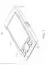
FIG. 2 is a first state of the electronic device, shown in FIG. 1.
FIG. 3 is a second state of the electronic device, shown in FIG. 1.
DETAILED DESCRIPTION OF EXEMPLARY EMBODIMENT
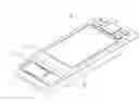
FIGS. 1 through 3 show an exemplary electronic device 10 including a cover member 11, a body member 12, and a chip card 13 (e.g., subscriber identity model card). The cover member 11 is slidably mounted to the body member 12. The chip card 13 is received in the body member 12 and shielded by the cover member 11.
The cover member 11 is a generally thin and sheet-shaped. The cover member 11 defines a display 111 and a plurality of buttons 112 adjacent to the display 111.
The body member 12 is also generally thin and sheet-shaped. The body member 12 includes a top end 121 and an opposite bottom end 122. The body member 12 defines a receiving cavity 123 adjacent to the top end 121. Two limiting blocks 1232 protrude from two opposite sidewalls 1231 of the receiving cavity 123 with a bottom wall 1233. A plurality of elastic connecting poles 1234 is disposed on the bottom wall 1233. The cover member 11 is slidably mounted to the body member 12 to expose or close off the receiving cavity 123.
The chip card 13 is a SIM card in the exemplary embodiment. The receiving cavity 123 is configured to receive the SIM card 13. At this time, the SIM card 13 is tightly latched by the two limiting blocks 1232 and electrically contacts the elastic connecting poles 1234.
To replace the SIM card 13, slide the cover member 11 towards the bottom end 122 of the body member 12 until the receiving cavity 123 is exposed. At this stage, a user can easily take out the SIM card 13.
The cover member 11 slides relative to the body member 12 to open or close the receiving cavity 123, thus it is convenient to replace the chip card 13, avoiding cutting off the power of the electronic device 10.
It is to be understood, however, that even through numerous characteristics and advantages of the present invention have been set forth in the foregoing description, together with details of the structure and function of the invention, the disclosure is illustrative only, and changes may be made in detail, especially in matters of shape, size, and arrangement of sections within the principles of the invention to the full extent indicated by the broad general meaning of the terms, in which the appended claims are expressed.
Claims
What is claimed is:1. An electronic device, comprising:
a body member defining a receiving cavity;
a chip card removably received in the receiving cavity; and
a cover member slidably mounted to the body member; wherein the cover is cable of sliding between an open and a closed position.
2. The electronic device as claimed in claim 1, wherein two limiting blocks protrude from two opposite sidewalls of the receiving cavity, the limiting blocks are capable of securing the chip card.
3. The electronic device as claimed in claim 1, wherein a bottom wall of the receiving cavity has a plurality of elastic connecting poles, the elastic connecting poles contact the chip card.
4. The electronic device as claimed in claim 1, wherein the chip card is a subscriber identity module card.
5. The electronic device as claimed in claim 1, wherein the cover member comprises of a display and a plurality of buttons.
6. A chip card holder used to hold a chip card therein, comprising:
a body member defining a receiving cavity, the chip card being removably received in the receiving cavity; and
a cover member slidably mounted to the body member;
wherein the cover is cable of sliding between an open and a closed position.
7. The chip card holder as claimed in claim 6, wherein the body member is a housing of an electronic device, and the cover member is another housing of the electronic device.
8. The chip card holder as claimed in claim 6, wherein two limiting blocks protrude from two opposite sidewalls of the receiving cavity, the limiting blocks are capable of securing the chip card.
9. The chip card holder as claimed in claim 6, wherein a bottom wall of the receiving cavity has a plurality of elastic connecting poles, the elastic connecting poles contact the chip card.
10. The chip card holder as claimed in claim 6, wherein the chip card is a subscriber identity module card.
11. The chip card holder as claimed in claim 6, wherein the cover member comprises of a display and a plurality of buttons.
Images & Drawings included:


Sources:
- United States Patent and Trademark Office - verify current appl. status at the USPTO↗
Similar patent applications:
- » 20220050687
METHOD OF BOOTING ELECTRONIC DEVICE AND ELECTRONIC DEVICE CONTROL SYSTEM, METHODS OF OPERATING AND CONTROLLING ELECTRONIC DEVICE, ELECTRONIC DEVICE, CONTROL TERMINAL, AND ELECTRONIC DEVICE CONTROL SYSTEM - » 20090136743
Substrate for electronic device, method for manufacturing the substrate for electronic device, electronic device provided with the substrate for electronic device, and electronic equipment provided with the electronic device - » 20120228782
METHOD FOR MANUFACTURING ELECTRONIC DEVICE, ELECTRONIC DEVICE, METHOD FOR MANUFACTURING ELECTRONIC DEVICE PACKAGE AND ELECTRONIC DEVICE PACKAGE - » 20110278635
Method for producing electronic device substrate, method for manufacturing electronic device, electronic device substrate, and electronic device - » 20100001388
Electronic device, electronic apparatus mounted with electronic device, article equipped with electronic device and method of producing electronic device - » 20100001387
Electronic device, electronic apparatus mounted with electronic device, article equipped with electronic device and method of producing electronic device - » 20110163456
Electronic device substrate, electronic device, method of manufacturing electronic device substrate, method of manufacturing electronic device, and electronic apparatus - » 20100001081
Electronic device, electronic apparatus mounted with electronic device, article equipped with electronic device and method of producing electronic device - » 20120059606
ELECTRONIC DEVICE, ELECTRONIC DEVICE MANAGEMENT SYSTEM, CONTROL METHOD OF ELECTRONIC DEVICE, CONTROL METHOD OF ELECTRONIC DEVICE MANAGEMENT SYSTEM, AND STORAGE MEDIUM - » 20170352537
Epitaxial substrate for electronic devices, electronic device, method for producing the epitaxial substrate for electronic devices, and method for producing the electronic device
Recent applications in this class:
- » 20240072834 2024-02-29
COMMUNICATION SYSTEM AND ELECTRONIC DEVICE - » 20220247444 2022-08-04
Electronic device and field device - » 20220190862 2022-06-16
Electronic device - » 20220123775 2022-04-21
Electronic device having removable tray - » 20200366326 2020-11-19
Systems and methods for signaling for AI use by mobile stations in wireless networks - » 20200195288 2020-06-18
Electronic device - » 20190229761 2019-07-25
Enhanced modem based carrier auto-selection algorithm - » 20190207637 2019-07-04
MOBILE COMMUNICATION SYSTEM, DIFFERENT MOBILE DEVICES SHARING SAME PHONE NUMBER ON MOBILE COMMUNICATION SYSTEM, AND METHOD OF PROVIDING MOBILE COMMUNICATION SERVICE BETWEEN DIFFERENT MOBILE DEVICES SHARING SAME PHONE NUMBER - » 20190190558 2019-06-20
Apparatus And Method For A Communication Network - » 20190181901 2019-06-13
LOCAL PROFILE ASSISTANT AND APPLICATION PROGRAMMING INTERFACE
Recent applications for this Assignee:
- » 20220140846 2022-05-05
Antenna structure and wireless communication device using same - » 20220094077 2022-03-24
Antenna structure and wireless communication device using same - » 20220059931 2022-02-24
Antenna structure and wireless communication device - » 20220021116 2022-01-20
Single antenna structure capable of operating in multiple band widths - » 20220010948 2022-01-13
Anti-loosing structure and backlight module - » 20200170133 2020-05-28
Housing, electronic device, and method for manufacturing same - » 20200122194 2020-04-23
Frame and surface treatment method for the frame - » 20200060034 2020-02-20
Housing, method for manufacturing the same, and electronic device having the same - » 20200016805 2020-01-16
Housing, electronic device, and method for manufacturing the same - » 20190368052 2019-12-05
COMPOSITE AND METHOD FOR MAKING SAME