KEYPAD ASSEMBLY
US20100147667A1
2010-06-17
12/393,148
2009-02-26
Abstract:
A keypad assembly used in a portable electronic device is described. The keypad assembly includes a shelf, a keypad mounted to the shelf, and at least one light-emitting source. The keypad is made of a light-guiding material. The light-emitting source faces the keypad and is adjacent to the keypad.
Assignee:
- FIH (HONG KONG) LIMITED 1,461 🇭🇰 Kowloon, Hong Kong
Interested in similar patents?
Get notified when new applications in this technology area are published.
Classification:
H01H13/83 » CPC main
Switches having rectilinearly-movable operating part or parts adapted for pushing or pulling in one direction only, e.g. push-button switch having a plurality of operating members associated with different sets of contacts, e.g. keyboard characterised by legends, e.g. Braille, liquid crystal displays, light emitting or optical elements
H01H2219/044 » CPC further
Legends; Light emitting elements Edge lighting of layer
H01H2219/062 » CPC further
Legends; Optical elements Light conductor
H01H2221/07 » CPC further
Actuators transparent
H01H2223/0345 » CPC further
Casings; Bezel with keys positioned directly next to each other without an intermediate bezel or frame
H01H13/76 IPC
Switches having rectilinearly-movable operating part or parts adapted for pushing or pulling in one direction only, e.g. push-button switch having a plurality of operating members associated with different sets of contacts, e.g. keyboard wherein some or all of the operating members actuate different combinations of the contact sets, e.g. ten operating members actuating different combinations of four contact sets
Description
BACKGROUND
1. Field of the Disclosure
The disclosure relates to keypad assemblies and, particularly, to an illuminated keypad assembly used in a portable electronic device.
2. Description of Related Art
With development of technology, portable electronic devices (e.g., mobile phones or personal digital handsets) are made available with ever-greater number of user-friendly functions, e.g., illuminated keypads etc.
A typical illuminated keypad transmits light using a light-guiding board. Thus, the keypad assembly can have a complex structure.
Therefore, there is room for improvement within the art.
BRIEF DESCRIPTION OF THE DRAWINGS
Many aspects of the keypad assembly can be better understood with reference to the following drawings. These drawings are not necessarily drawn to scale, the emphasis instead being placed upon clearly illustrating the principles of the present keypad assembly. Moreover, in the drawings like reference numerals designate corresponding members throughout the several views.
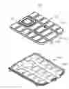
FIG. 1 is an exploded, isometric view of a keypad assembly, in accordance with an exemplary embodiment.
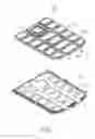
FIG. 2 is a cross-sectional view of the keypad assembly shown in FIG. 1.
DETAILED DESCRIPTION OF EXEMPLARY EMBODIMENT
FIGS. 1 and 2 show an exemplary embodiment of a keypad assembly 20 used in a portable electronic device (e.g., mobile phone). The keypad assembly 20 includes a keypad 21, a shelf 22, and two light-emitting sources 23. The keypad 21 is mounted to the shelf 22. The light-emitting sources 23 are adjacent to the keypad 21.
The keypad 21 is made of a light-guiding material and includes a first end 211 and a second end 212. The keypad 21 forms a plurality of buttons 213.
The shelf 22 is generally planar, with button receiving cavities 221 defined therein. Each cavity 221 is configured to receive one button 213. The buttons 213 can be depressed into the cavities 221 to contact signal-sensing portions of a printed circuit board (not shown).
Each light-emitting source 23 is a light-emitting diode (LED). The LEDs are electrically mounted to the printed circuit board adjacent to the second end 212 of the keypad 21.
In use, most of the light emitted from the light-emitting sources 23 penetrates into the light-guiding material of keypad 21. Due to the light-guiding ability of the keypad 21, the light is then transmitted to each button 213 and illuminates the whole keypad assembly 20, thus eliminating the need for a separate light-guiding board. Therefore, the keypad assembly 20 is less complex and thus simpler to manufacture.
It is to be understood, however, that even through numerous characteristics and advantages of the present disclosed have been set forth in the foregoing description, together with details of the structure and function of the keypad assemble, the disclosure is illustrative only, and changes may be made in detail, especially in matters of shape, size, and arrangement of members within the principles of the invention to the full extent indicated by the broad general meaning of the terms, in which the appended claims are expressed.
Claims
What is claimed is:1. A keypad assembly, comprising:
a shelf;
a keypad made of a light-guiding material, the keypad being mounted to the shelf; and
at least one light-emitting source facing the keypad and being adjacent to the keypad.
2. The keypad assembly as claimed in claim 1, wherein the keypad defines a plurality of buttons.
3. The keypad assembly as claimed in claim 2, wherein the shelf defines a plurality of button receiving cavities, each button being moveably received in a corresponding button receiving cavity.
4. The keypad assembly as claimed in claim 1, wherein the light-emitting source is a light-emitting diode.
5. A portable electronic device, comprising:
a shelf;
a keypad made of a light-guiding material, the keypad being mounted to the shelf; and
at least one light-emitting source facing the keypad, the light-emitting source being adjacent to the keypad.
6. The portable electronic device as claimed in claim 5, wherein the keypad defines a plurality of buttons.
7. The portable electronic device as claimed in claim 6, wherein the shelf defines a plurality of button receiving cavities, each button being moveably received in a corresponding button receiving cavity.
8. The portable electronic device as claimed in claim 5, wherein the light-emitting source is a light-emitting diode.
Images & Drawings included:

Sources:
- United States Patent and Trademark Office - verify current appl. status at the USPTO↗
Similar patent applications:
- » 20190138202
Heatable vehicle keypad assembly and keypad heating method - » 20120200994
Keypad assembly with a contoured keypad facade for a mobile computing device - » 20070205986
Metal Keypad Assembly for Mobile Phone and Manufacturing Method of Keypad - » 20090095613
Key button, key assembly using the key button and portable electronic device using the keypad assembly - » 20100025212
Key button and key assembly using the key button and portable electronic device using the keypad assembly - » 20060024110
Thin keypad assemblies and components for electronics devices and methods - » 20050237229
Self contained keypad assembly - » 20050068201
Method and system for assembling keypad - » 20060063571
Hand-held communication device keypad assembly - » 20050202787
Keypad assembly
Recent applications in this class:
- » 20250140493 2025-05-01
ICON DISPLAY MODULE - » 20250095930 2025-03-20
BACKLIT CIRCUIT BOARD, BACKLIT MODULE, BACKLIT KEYSWITCH AND KEYBOARD - » 20250014849 2025-01-09
SEE-THROUGH KEY MODULE AND CONTROL DEVICE WITH SAME - » 20250014848 2025-01-09
CONTROL DEVICE - » 20240429005 2024-12-26
TOUCH LIGHTING KEYSWITCH AND TOUCH LIGHTING FUNCTION KEY BAR - » 20240395481 2024-11-28
KEYCAP AND MANUFACTURING METHOD THEREOF - » 20240222046 2024-07-04
CONTROL DEVICES HAVING INDEPENDENTLY SUSPENDED BUTTONS FOR CONTROLLED ACTUATION - » 20240186080 2024-06-06
ILLUMINATED KEYSWITCH STRUCTURE AND ILLUMINATING MODULE - » 20240177950 2024-05-30
Lighting keyboard, backlight module and lighting board - » 20240170237 2024-05-23
KEYBOARD AND KEY MODULE THEREOF
Recent applications for this Assignee:
- » 20220140846 2022-05-05
Antenna structure and wireless communication device using same - » 20220094077 2022-03-24
Antenna structure and wireless communication device using same - » 20220059931 2022-02-24
Antenna structure and wireless communication device - » 20220021116 2022-01-20
Single antenna structure capable of operating in multiple band widths - » 20220010948 2022-01-13
Anti-loosing structure and backlight module - » 20200170133 2020-05-28
Housing, electronic device, and method for manufacturing same - » 20200122194 2020-04-23
Frame and surface treatment method for the frame - » 20200060034 2020-02-20
Housing, method for manufacturing the same, and electronic device having the same - » 20200016805 2020-01-16
Housing, electronic device, and method for manufacturing the same - » 20190368052 2019-12-05
COMPOSITE AND METHOD FOR MAKING SAME