PROJECTION-USE ZOOM LENS
US20100149655A1
2010-06-17
12/088,201
2006-09-26
Abstract:
The present invention provides a zoom lens having fewer constituting lenses and capable of easily keeping telecentricity. From a projection plane side, lens groups ranging from a first lens group to a fourth lens group are disposed, sequentially. The first lens group consists of the three lenses, one negative lens, one positive lens and one negative lens arranged sequentially from the projection plane side, and has a negative power. The second lens group consists of three lenses in total, that is, one positive lens, one compound lens and one compound lens arranged sequentially from the projection plane PL side and has a positive power. The third lens group consists of one negative lens. The fourth lens group consists of one positive lens. At power varying, the first lens group and the second lens group are moved with the third lens group and the fourth lens group kept fixed. The third lens group is moved for focusing.
Assignee:
- BROTHER KOGYO KABUSHIKI KAISHA 173 🇯🇵 Nagoya-shi, Aichi, Japan
Interested in similar patents?
Get notified when new applications in this technology area are published.
Classification:
G02B15/144511 » CPC main
Optical objectives with means for varying the magnification by axial movement of one or more lenses or groups of lenses relative to the image plane for continuously varying the equivalent focal length of the objective having four groups only the first group being negative arranged -+-+
G02B13/22 » CPC further
Optical objectives specially designed for the purposes specified below Telecentric objectives or lens systems
G02B15/14 IPC
Optical objectives with means for varying the magnification by axial movement of one or more lenses or groups of lenses relative to the image plane for continuously varying the equivalent focal length of the objective
Description
CROSS-REFERENCE TO RELATED APPLICATIONS
The present application is a Continuation-in-Part of International Application No. PCT/JP2006/319081 filed Sep. 26, 2006, which claims the benefits of Japanese Patent Application No. 2005-277953 filed September 26, Japanese Patent Application No. 2005-277952 filed Sep. 26, 2005, and Japanese Patent Application No. 2006-082099 filed Mar. 24, 2006.
BACKGROUND OF THE INVENTION
1. Field of the Invention
The present invention relates to a zoom lens used in a projection optical system.
2. Description of the Related Arts
Conventionally, as a projection-use zoom lens, optical systems of various types have been proposed. For example, the optical systems described in patent document 1 (JP-A-2004-77950), patent document 2 (JP-A-2004-54021), patent document 3 (JP-A-2003-215453), patent document 4 (JP-A-2003-215455) and patent document 5 (JP-A-2000-292698) have been proposed.
However, with respect to the optical systems described in these patent documents 1 to 5, the number of constituting lenses is nine or more thus giving rise to a drawback that a lens system becomes large-sized in addition to the increase of a lens cost. Here, in this specification, a compound lens equivalent to a single lens in terms of power is counted as one lens as a whole. “A compound lens equivalent to a single lens in terms of power” implies a compound lens consisting of lenses with cemented leens surfaces having the same radius of curvature (R). In general, with respect to the lenses which constitute such a compound lens, refractive indexes are made different from each other between the neighboring lenses so as to realize achromatization. However, in this specification, even when the refractive indexes of the neighboring lenses have the same refractive index, provided that the cemented lens surfaces of the neighboring lenses have the same radius of curvature (R), such a compound lens is considered as “a compound lens equivalent to a single lens in terms of power”.
Further, in view of the light emitting characteristic of an image element (that is, in view of a fact that when light incident on liquid crystal or an optical element part such as prism has an angle, the light possesses the polarization property and hence, chromaticity is changed or reflectance is deteriorated), it is preferable to design the projection-use zoom lens by imparting telecentricity (particularly, telecentricity on an image side) to the projection-use zoom lens. On the other hand, in the projection-use zoom lens, focusing is performed using a lens close to the image element in general. Accordingly, in the conventional focusing lens, it is also necessary to take the telecentricity into consideration. For example, recently, for the purpose of projecting a larger quantity of light of the image element as well as for miniaturizing a lens system, a condensing lens is arranged directly in front of an image element in general. In this case, however, when a focusing lens arranged close to the image element is constituted of one positive lens, there arises a drawback that the telecentricity is deteriorated.
SUMMARY OF THE INVENTION
The present invention has been made in view of the above-mentioned circumstances. It is an object of the present invention to provide a projection-use zoom lens having the fewer constituting lenses than a conventional projection-use zoom lens. It is another object of the present invention to provide a projection-use zoom lens which can easily keep telecentricity.
To achieve the above-mentioned objects, according to a first aspect of the present invention, there is provided a zoom lens including a first lens group, a second lens group, a third lens group and a fourth lens group arranged sequentially from a projection plane side and capable of varying power between a short focal end and a long focal end thereof. The first lens group is constituted of three lenses consisting of one negative lens, one positive lens and one negative lens arranged sequentially from the projection plane side and has a negative power. The second lens group is constituted of three lenses in total consisting of one compound lens or one positive lens, one positive lens or one compound lens, and one compound lens arranged sequentially from the projection plane side and has a positive power. The third lens group is constituted of one negative lens. The fourth lens group is constituted of one positive lens. In varying power, the zoom lens is configured such that the first lens group and the second lens group are moved, while the third lens group and the fourth lens group are fixed and, further, the zoom lens is configured to move the third lens group for focusing.
In this zoom lens, a focal length can be varied by moving the first lens group and the second lens group. Further, in this zoom lens, focusing can be performed by moving the third lens group.
Further, the fourth lens group constitutes a condensing lens for projecting a larger quantity of light of an image element and, at the same time, for reducing an outer diameter of a lens system. According to the present invention, the zoom lens is configured to keep telecentricity due to an optical system ranging from the first lens group to the fourth lens group. Here, keeping of telecentricity implies a state where a main light beam and an optical axis are arranged substantially parallel to each other (including inclination of approximately ±10°)
The zoom lens of the present invention may be configured to satisfy a following conditional expression (1).
0.7≦|f2/f1|≦1.5 (1)
f1: combined focal length of the first lens group
f2: combined focal length of the second lens group
The zoom lens of the present invention may be configured to satisfy a following conditional expression (2).
1.5≦|fb/fw|≦2.5 (2)
fb: combined back focusing ranging from the first lens group to the third lens group
fw: focal length at the short focal end
The zoom lens of the present invention may be configured to satisfy a following conditional expression (3).
0.08≦|fT/f3|≦0.3 (3)
f3: combined focal length of the third lens group
fT: focal length at the long focal end
A projector according to the present invention includes the above-mentioned zoom lens according to the present invention.
The above-mentioned conditional expressions (1) to (3) are explained hereinafter.
The conditional expression (1) is a condition for restricting the relationship between focal lengths of the first lens group and the second lens group which are moved for changing the focal lengths. When |f2/f2| assumes a value below a lower limit 0.7, the focal length of the first lens group becomes excessively large and hence, moving quantities of the first lens group and the second lens group for changing the focal lengths are increased thus eventually making the lens system large-sized. Accordingly, it is not favorable to set |f2/f1| to the value below the lower limit 0.7.
Further, when |f2/f1| assumes a value above an upper limit 1.5, such setting of |f2/f1| is advantageous for making the lens small-sized. However, the focal length of the first lens group becomes excessively small and hence, spherical aberration generated in the first lens group becomes excessively large. Accordingly, it is difficult to favorably correct the spherical aberration.
The conditional expression (2) is a condition for ensuring an air gap for inserting an illumination optical system between the third lens group and the fourth lens group for properly ensuring a light quantity of a projected image by setting a combined back focusing ranging from the first lens group to the third lens group to a predetermined size. When |fb/fw| assumes a value below a lower limit 1.5, the air gap between the third lens group and the fourth lens group becomes excessively small and hence, the illumination optical system cannot be inserted into the air gap.
Further, when |fb/fw| assumes a value above an upper limit 2.5, it is advantageous for ensuring the air gap between the third lens group and the fourth lens group for inserting the illumination optical system into the air gap. However, focal lengths of negative lenses of the first lens group and the third lens group become excessively small thus eventually increasing comatic aberration. Accordingly, it is not favorable to set |fb/fw| to the value above the upper limit 2.5.
The conditional expression (3) is a condition for properly keeping telecentricity of the optical system which performs focusing the third lens group and arranges a condensing lens directly in front of an image element. When |fT/f3| assumes a value below a lower limit 0.08, the focal length of the third lens group becomes excessively large and hence, a moving quantity of the third lens group in focusing becomes excessively large thus eventually making the lens group large-sized. Accordingly, it is not favorable to set |fT/f3| to the value below the lower limit 0.08.
Further, when |fT/f3| assumes a value above an upper limit 0.3, the moving quantity of the third lens group for focusing is decreased and hence, such setting of |fT/f3| to the value above the upper limit 0.3 is advantageous for making the lens system small-sized. However, in this case, it is difficult for the lens system to keep telecentricity and, at the same time, the spherical aberration is excessively increased. Accordingly, it is not favorable to set |fT/f3| to the value above the upper limit 0.3.
According to another aspect of the present invention, there is provided a zoom lens including a first lens group, a second lens group and a third lens group arranged sequentially from a projection plane side and capable of varying power between a short focal end and a long focal end thereof. The first lens group is constituted of three lenses consisting of one negative lens, one positive lens and one negative lens arranged sequentially from the projection plane side and has a negative power. The second lens group is constituted of three lenses in total consisting of one positive lens, one compound lens constituted of two lenses, and one compound lens constituted of two lenses arranged sequentially from the projection plane side and has a positive power. The third lens group is constituted of two lenses consisting of one negative lens and one positive lens arranged sequentially from the projection plane side and has a positive power. Further, in the zoom lens of the present invention, in varying power, the zoom lens is configured such that the first lens group and the second lens group are moved, while the third lens group is fixed. Further, the zoom lens is configured to move the third lens group for focusing.
In this zoom lens, a focal length can be varied by moving the first lens group and the second lens group. Further, in this zoom lens, focusing can be performed by moving the third lens group.
Further, according to the present invention, by designing the zoom lens which satisfies conditional expressions (4) to (6) described later, the zoom Jens can be configured to keep telecentricity due to an optical system ranging from the first lens group to the third Jens group. Here, keeping of telecentricity implies a state where a main light beam and an optical axis are arranged substantially parallel to each other (including inclination of approximately ±10°).
The zoom lens of the present invention may be configured to satisfy a following conditional expression (4).
0.6≦|f2/f1|≦1.3 (4)
f1: combined focal length of the first lens group
f2: combined focal length of the second lens group
The zoom lens of the present invention may be configured to satisfy a following conditional expression (5).
0.8≦|fb/fw|≦1.8 (5)
fb: combined back focusing ranging from the first lens group to the third lens group
fw: focal length at the short focal end
The zoom lens of the present invention may be configured to satisfy a following conditional expression (6).
0.08≦|ft/f3|≦0.3 (6)
f3: combined focal length of the third lens group
ft: focal length at the long focal end
A projector according to the present invention includes a zoom lens according to the present invention.
The above-mentioned conditional expressions (4) to (6) are explained hereinafter.
The conditional expression (4) is a condition for restricting the relationship between focal lengths of the first lens group and the second lens group which are moved for changing the focal lengths. When |f2/f1| assumes a value below a lower limit 0.6, the focal length of the first lens group becomes excessively large and hence, moving quantities of the first lens group and the second lens group for changing the focal lengths are increased thus eventually making the lens system large-sized. Accordingly, it is not favorable to set |f2/f1| to the value below the lower limit 0.6.
further, when |f2/f1| assumes a value above an upper limit 1.3, such setting of |f2/f1| is advantageous for making the lens small-sized. However, the focal length of the first lens group becomes excessively small and hence, spherical aberration generated in the first lens group becomes excessively large. Accordingly, it is difficult to favorably correct the spherical aberration.
The conditional expression (5) is a condition for ensuring an air gap for inserting an illumination optical system between the third lens group and the image element for properly ensuring a light quantity of a projected image by setting a combined back focusing ranging from the first lens group to the third lens group to a predetermined size. When |fb/fw| assumes a value below a lower limit 0.8, the air gap between the third lens group and the image element becomes excessively small and hence, the illumination optical system cannot be inserted into the air gap.
Further, when |fb/fw| assumes a value above an upper limit 1.8, it is advantageous for ensuring the air gap between the third lens group and the image element for inserting the illumination optical system in the air gap. However, focal lengths of negative lenses of the first lens group and the third lens group become excessively small thus eventually increasing comatic aberration. Accordingly, it is not favorable to set |fb/fw| to the value above the upper limit 1.8.
The conditional expression (6) is a condition for properly keeping telecentricity of the lens system which performs focusing the third lens group. When |ft/f3| assumes a value below a lower limit 0.08, the focal length of the third lens group becomes excessively large and hence, a moving quantity of the third lens group in focusing becomes excessively large thus eventually making the lens group large-sized. Accordingly, it is not favorable to set |ft/f3| to the value below the lower limit 0.08.
Further, when |ft/fs| assumes a value above an upper limit 0.3, the moving quantity of the third lens group for focusing is decreased and hence, such setting of |ft/f3| to the value above the upper limit 0.3 is advantageous for making the lens system small-sized. However, in this case, it is difficult for the lens system to keep telecentricity and, at the same time, the spherical aberration is excessively decreased. Accordingly, it is not favorable to set |ft/f3| to the value above the upper limit 0.3.
According to the present invention, it is possible to provide a projection-use zoom lens in which the number of constituting lenses is eight, that is, the smaller number of conventional constituting lenses. Further, according to the present invention, it is possible to provide a projection-use zoom lens which can easily keep telecentricity.
BRIEF EXPLANATION OF THE DRAWINGS
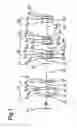
FIG. 1 is an explanatory view showing the constitution of a lens of a numerical-value example 1 according to a first embodiment;
FIG. 2 is a view showing various aberrations at a short focal end of the numerical-value example 1 according to the first embodiment;
FIG. 3 is a view showing various aberrations at an intermediate focal position of the numerical-value example 1 according to the first embodiment;
FIG. 4 is a view showing various aberrations at a long focal end of the numerical-value example 1 according to the first embodiment;
FIG. 5 is an explanatory view showing the constitution of a lens of a numerical-value example 2 according to the first embodiment;
FIG. 6 is a view showing various aberrations at a short focal end of the numerical-value example 2 according to the first embodiment;
FIG. 7 is a view showing various aberrations at an intermediate focal position of the numerical-value example 2 according to the first embodiment;
FIG. 8 is a view showing various aberrations at a long focal end of the numerical-value example 2 according to the first embodiment;
FIG. 9 is an explanatory view showing the constitution of a lens of a numerical-value example 3 according to the first embodiment;
FIG. 10 is a view showing various aberrations at a short focal end of the numerical-value example 3 according to the first embodiment;
FIG. 11 is a view showing various aberrations at an intermediate focal position of the numerical-value example 3 according to the first embodiment;
FIG. 12 is a view showing various aberrations at a long focal end of the numerical-value example 3 according to the first embodiment;
FIG. 13 is an explanatory view showing the constitution of a lens of a numerical-value example 1 according to a second embodiment;
FIG. 14 is a view showing various aberrations at a short focal end of the numerical-value example 1 according to the second embodiment;
FIG. 15 is a view showing various aberrations at an intermediate focal position of the numerical-value example 1 according to the second embodiment;
FIG. 16 is a view showing various aberrations at a long focal end of the numerical-value example 1 according to the second embodiment;
FIG. 17 is an explanatory view showing the constitution of a lens of a numerical-value example 2 according to the second embodiment;
FIG. 18 is a view showing various aberrations at a short focal end of the numerical-value example 2 according to the second embodiment;
FIG. 19 is a view showing various aberrations at an intermediate focal position of the numerical-value example 2 according to the second embodiment;
FIG. 20 is a view showing various aberrations at a long focal end of the numerical-value example 2 according to the second embodiment;
FIG. 21 is an explanatory view showing the constitution of a lens of a numerical-value example 3 according to the second embodiment;
FIG. 22 is a view showing various aberrations at a short focal end of the numerical-value example 3 according to the second embodiment;
FIG. 23 is a view showing various aberrations at an intermediate focal position of the numerical-value example 3 according to the second embodiment;
FIG. 24 is a view showing various aberrations at a long focal end of the numerical-value example 3 according to the second embodiment;
FIG. 25 is an explanatory view showing the constitution of a lens of a numerical-value example 1 according to the third embodiment;
FIG. 26 is a view showing various aberrations at a short focal end of the numerical-value example 1 according to the third embodiment;
FIG. 27 is a view showing various aberrations at an intermediate focal position of the numerical-value example 1 according to the third embodiment;
FIG. 28 is a view showing various aberrations at a long focal end of the numerical-value example 1 according to the third embodiment;
FIG. 29 is an explanatory view showing the constitution of a lens of a numerical-value example 2 according to the third embodiment;
FIG. 30 is a view showing various aberrations at a short focal end of the numerical-value example 2 according to the third embodiment;
FIG. 31 is a view showing various aberrations at an intermediate focal position of the numerical-value example 2 according to the third embodiment;
FIG. 32 is a view showing various aberrations at a long focal end of the numerical-value example 2 according to the third embodiment;
FIG. 33 is an explanatory view showing the constitution of a lens of a numerical-value example 3 according to the third embodiment;
FIG. 34 is a view showing various aberrations at a short focal end of the numerical-value example 3 according to the third embodiment;
FIG. 35 is a view showing various aberrations at an intermediate focal position of the numerical-value example 3 according to the third embodiment; and
FIG. 36 is a view showing various aberrations at a long focal end of the numerical-value example 3 according to the third embodiment.
DESCRIPTION OF THE PREFERRED EMBODIMENTS
First Embodiment
First of all, a zoom lens of a first embodiment is explained. A zoom lens of the first embodiment is constituted of a first lens group, a second lens group, a third lens group and a fourth lens group arranged sequentially from a projection plane side and capable of varying power between a short focal end and a long focal end, wherein the first lens group is constituted of three lenses consisting of one negative lens, one positive lens and one negative lens arranged sequentially from the projection plane side and has a negative power, the second lens group is constituted of three lenses in total consisting of one compound lens, one positive lens and one compound lens arranged sequentially from the projection plane aide and has a positive power, the third lens group is constituted of one negative lens, and the fourth lens group is constituted of one positive lens and, in varying power, the zoom lens is configured such that the first lens group and the second lens group are moved, while the third lens group and the fourth lens group are fixed and, further, the zoom lens is configured to move the third lens group for focusing.
Next, a specific numerical-value example according to the first embodiment is explained.
(Constitution of Numerical-Value Example 1 According to First Embodiment)
FIG. 1 shows the constitution of a zoom lens according to the numerical-value example 1 according to the first embodiment. In FIG. 1, symbol PL indicates a projection plane, symbol CD indicates an imaging element, symbol GL indicates a protection glass (here, including an optical filter or the like) of the imaging element or the like, symbol G1 indicates a first lens group, symbol G2 indicates a second lens group, symbol G3 indicates a third lens group, and symbol G4 indicates a fourth lens group. Here, symbol R7 indicates a stop surface.
This zoom lens is constituted of a first lens group G1, a second lens group Gtr a third lens group G3 and a fourth lens group G4 arranged sequentially from a projection plane PL side. The zoom lens can vary power between a short focal end and a long focal end.
The first lens group G1 is constituted of three lenses consisting of one negative lens, one positive lens and one negative lens arranged sequentially from the projection plane side and has a negative power. Here, one lens which constitutes each lens group as a unit may be formed of, as described above, the compound lens equivalent to a single lens in terms of power. Here, the compound lens indicates a lens formed by cementing two or more single lenses.
The second lens group G2 is constituted of one compound lens (R8 to R10), one positive lens (R11 to R12) and one compound lens (R13 to R15) arranged sequentially from the projection plane PL side and has a positive power. In the first embodiment, all compound lenses are respectively constituted of two lenses. With respect to the above-mentioned respective compound lenses, either or both of the compound lenses may be constituted of three or more lenses instead of two lenses. Further, the above-mentioned one positive lens (R11 to R12) may be constituted of one compound lens.
The third lens group G3 is constituted of one negative lens. This negative lens may be also constituted of one compound lens having a negative power.
The fourth lens group G4 is constituted of one positive lens. This positive lens may be also constituted of one compound lens having a positive power.
Accordingly, the zoom lens of the first embodiment is constituted of eight lenses in total. Here, as described above, the compound lens equivalent to the single lens in terms of power is counted as one lens.
In the first embodiment, in varying power, the zoom lens is configured such that the first lens group G1 and the second lens group G2 are moved, while the third lens group G3 and the fourth lens group G4 are fixed. Further, in the first embodiment, the zoom lens is configured to move the third lens group G3 for focusing. A mechanism for moving such lens groups per se is substantially equal to a conventional corresponding lens group moving mechanism and hence, the detailed explanation of the lens group moving mechanism is omitted.
(Properties of Numerical-Value Example 1 According to First Embodiment)
FIG. 2 to FIG. 4 show various aberrations of a numerical-value example 1. FIG. 2 shows various aberrations at a short focal end of the numerical-value example 1. FIG. 3 shows various aberrations at an intermediate focal position of the numerical-value example 1. FIG. 4 shows various aberrations at a long focal end of the numerical-value example 1.
In these drawings, symbols G, B, R in chromatic aberration expressed by spherical aberrations are, respectively, spherical chromatic aberrations corresponding to wavelengths of green, blue, red., and symbol SC indicates a sine condition unsatisfactory quantity.
In astigmatism, symbol S indicates sagittal and symbol M indicates meridional.
Further, various properties of the numerical-value example 1 are shown in Table 1,
| TABLE 1 | ||||
| R | d | Nd | Vd | |
| 1 | 44.107 | 2.00 | 1.80420 | 46.5 |
| 2 | 27.702 | 9.90 | ||
| 3 | −120.986 | 4.09 | 1.80420 | 46.5 |
| 4 | −49.048 | 8.53 | ||
| 5 | −31.433 | 1.50 | 1.48749 | 70.4 |
| 6 | 24.430 | 29.54 | ||
| 7 | ∞ | 8.00 | ||
| 8 | 141.659 | 1.50 | 1.83400 | 37.3 |
| 9 | 25.491 | 6.22 | 1.80420 | 46.5 |
| 10 | −58.563 | .10 | ||
| 11 | 24.917 | 5.00 | 1.83400 | 37.3 |
| 12 | 32.667 | 10.90 | ||
| 13 | 37.268 | 1.00 | 1.80518 | 25.4 |
| 14 | 15.165 | 7.49 | 1.48749 | 70.4 |
| 15 | −48.389 | 2.51 | ||
| 16 | −20.814 | 1.62 | 1.48749 | 70.4 |
| 17 | −28.034 | 25.00 | ||
| 18 | 49.471 | 5.48 | 1.58913 | 61.2 |
| 19 | ∞ | |||
| short focal | intermediate | long focal | |
| length end | focal length | length end | |
| aperture ratio 1: | 2.40 | 2.54 | 2.69 |
| focal length | 18.882 | 23.525 | 28.199 |
| angle of projected | 57.8 | 47.2 | 39.5 |
| view (degree) | |||
| variable interval | 29.550 | 20.776 | 14.874 |
| d 6 | |||
| variable interval | 2.515 | 7.457 | 12.447 |
| d 15 | |||
| incident angle to | 5.6 | 5.1 | 4.7 |
| element of principal ray | |||
| (degree) (telecentric property) | |||
| projector distance | 1000 | |
| zooming power | 1.5 | |
| fw | 18.882 | |
| ft | 28.199 | |
| f1 | −25.688 | |
| f2 | 29.614 | |
| f3 | −178.401 | |
| fb | 32.309 | |
| f2/f1 | −1.153 | |
| fb/fw | 1.711 | |
| ft/f3 | −0.158 | |
In Table 1, symbol R indicates a radius of curvature, symbol d indicates a lens thickness or an air gap, symbol Nd indicates a refractive index of a d line (588 nm), and symbol Vd indicates Abbe's number of the d line (Abbe's number also indicated by symbol vd). The relationship between a subscript of the symbol R and the lens and the relationship between a subscript of the symbol d and the lens are set as shown in FIG. 1. Further, in Table 1, symbol f1 indicates a focal length of the first lens group G1, symbol f2 indicates a focal length of the second lens group G2, and symbol f3 indicates a focal length of the third lens group G3.
Further, in Table 1, symbol indicates a focal length at the short focal end, symbol fT indicates a focal length at the long focal end, and symbol fb indicates combined back focusing from the first lens group G1 to the third lens group G3.
Further, a projection distance is set to 1000 mm in the first embodiment.
With the use of the zoom lens of the numerical-value example 1, it is possible to provide a projection-use zoom lens constituted of lenses smaller in number than the conventional zoom lens, that is, 8 lenses. Here, as described above, the compound lens equivalent to a single lens in terms of power is counted as one lens. Further, in the zoom lens of this first embodiment, the focusing lens is constituted of the negative lens. Accordingly, the zoom lens has an advantage that, even in an optical system which arranges a condensing lens (that is, the fourth lens group G4) directly frontward of the image element, the optical system can easily keep telecentricity. The telecentricity obtained, by this embodiment is as described in Table 1.
The zoom lens according to the first embodiment can be used as a projection-use lens for a projector.
(Constitution of Numerical-Value Example 2 According to First Embodiment)
Next, the constitution of a zoom lens of the numerical-value example 2 according to the first embodiment is shown in FIG. 5, Here, in the explanation of the numerical-value example 2, with respect to the constitutional elements and properties substantially equal to the constitutional elements and the properties of the numerical-value example 1, the explanation is simplified by using the same symbols.
Various aberrations of the numerical-value example 2 are shown in FIG. 6 to FIG. 8. FIG. 6 shows various aberrations at a short focal end, FIG. 7 shows various aberrations at an intermediate focal position, and FIG. 8 shows various aberrations at a long focal end. Further, various properties of the numerical-value example 2 are shown in Table 2.
| TABLE 2 | ||||
| R | d | Nd | Vd | |
| 1 | 49.812 | 2.00 | 1.80420 | 46.50 |
| 2 | 27.023 | 11.68 | ||
| 3 | −63.436 | 5.55 | 1.80420 | 46.50 |
| 4 | −39.160 | 11.60 | ||
| 5 | −27.450 | 1.50 | 1.48749 | 70.45 |
| 6 | 96.853 | 25.47 | ||
| 7 | ∞ | 8.00 | ||
| 8 | −123.785 | 10.00 | 1.83400 | 37.34 |
| 9 | 22.046 | 10.00 | 1.80420 | 46.50 |
| 10 | −52.132 | .10 | ||
| 11 | 32.230 | 3.05 | 1.83400 | 37.34 |
| 12 | 95.673 | 15.00 | ||
| 13 | 39.478 | 4.80 | 1.80518 | 25.46 |
| 14 | 15.316 | 6.76 | 1.48749 | 70.45 |
| 15 | −99.727 | 2.25 | ||
| 16 | −29.264 | 1.63 | 1.48749 | 70.45 |
| 17 | −45.890 | 22.00 | ||
| 18 | 54.598 | 9.00 | 1.58913 | 61.25 |
| 19 | ∞ | |||
| short focal | intermediate | long focal | |
| length end | focal length | length end | |
| aperture ratio 1: | 2.40 | 2.52 | 2.65 |
| focal length | 19.562 | 26.338 | 34.132 |
| angle of projected | 56.1 | 42.4 | 32.7 |
| view (degree) | |||
| variable interval | 25.471 | 10.916 | 1.344 |
| d 6 | |||
| variable interval | 2.259 | 8.623 | 15.992 |
| d 15 | |||
| incident angle to | 6.0 | 5.6 | 5.3 |
| element of principal ray | |||
| (degree) (telecentricity) | |||
| projector distance | 1000 | |
| zooming power | 1.75 | |
| fw | 19.562 | |
| ft | 34.132 | |
| f1 | −232.147 | |
| f2 | 31.784 | |
| f3 | −170.660 | |
| fb | 31.855 | |
| f2/f1 | −0.989 | |
| fb/fw | 1.628 | |
| ft/f3 | −0.200 | |
Other constitutions and advantages of the numerical-value example 2 are substantially equal to the constitutions and advantages of the numerical-value example 1 and hence, the more detailed explanation is omitted.
(Constitution of Numerical-Value Example 3 According to First Embodiment)
Next, FIG. 9 shows the constitution of a zoom lens of the numerical-value example 3 according to the first embodiment. Here, in the explanation of the numerical-value example 3, with respect to the constitutional elements and properties substantially equal to the constitutional elements and the properties of the numerical-value example 1, the explanation is simplified by using the same symbols.
FIG. 10 to FIG. 12 show various aberrations of the numerical-value example 3. FIG. 10 shows various aberrations at a short focal end, FIG. 11 shows various aberrations at an intermediate focal position, and FIG. 12 shows various aberrations at a long focal end. Further, various properties of the numerical-value example 3 are shown in Table 3.
| TABLE 3 | ||||
| R | d | Nd | Vd | |
| 1 | 79.191 | 2.00 | 1.80420 | 46.50 |
| 2 | 29.385 | 11.51 | ||
| 3 | −51.989 | 5.66 | 1.80420 | 46.50 |
| 4 | −35.000 | 10.64 | ||
| 5 | −28.191 | 1.50 | 1.48749 | 70.45 |
| 6 | −243.798 | 38.35 | ||
| 7 | ∞ | 8.00 | ||
| 8 | 205.418 | 1.51 | 1.83400 | 37.34 |
| 9 | 39.209 | 4.45 | 1.80420 | 46.50 |
| 10 | −83.634 | .15 | ||
| 11 | 29.225 | 2.60 | 1.83400 | 37.34 |
| 12 | 52.209 | 15.00 | ||
| 13 | 39.659 | 1.00 | 1.80518 | 25.46 |
| 14 | 15.610 | 6.52 | 1.48749 | 70.45 |
| 15 | −123.274 | 3.29 | ||
| 16 | −19.842 | 2.22 | 1.48749 | 70.45 |
| 17 | −22.580 | 22.11 | ||
| 18 | 50.627 | 8.86 | 1.58913 | 61.25 |
| 19 | ∞ | |||
| short focal | intermediate | long focal | |
| length end | focal length | length end | |
| aperture ratio 1: | 2.40 | 2.71 | 3.03 |
| focal length | 19.672 | 29.523 | 39.147 |
| angle of projected | 55.9 | 37.8 | 28.5 |
| view (degree) | |||
| variable interval | 38.353 | 15.740 | 4.701 |
| d 6 | |||
| variable interval | 3.299 | 12.874 | 32.396 |
| d 15 | |||
| incident angle to | 6.0 | 5.0 | 4.2 |
| element of principal ray | |||
| (degree) (telecentric property) | |||
| projector distance | 1000 | |
| zooming power | 2.0 | |
| fw | 19.672 | |
| ft | 39.147 | |
| f1 | −38.165 | |
| f2 | 35.536 | |
| f3 | −456.590 | |
| fb | 31.926 | |
| f2/f1 | −0.931 | |
| fb/fw | 1.623 | |
| ft/f3 | −0.086 | |
Other constitutions and advantages of the numerical-value example 3 are substantially equal to the constitutions and advantages of the numerical-value example 1 and hence, the more detailed explanation is omitted.
Second Embodiment
Next, a zoom lens of a second embodiment is explained. A zoom lens of the second embodiment is constituted of a first lens group, a second lens group, a third lens group and a fourth lens group arranged sequentially from a projection plane side and capable of varying power between a short focal end and a long focal end, wherein the first lens group is constituted of three lenses consisting of one negative lens, one positive lens and one negative lens arranged sequentially from the projection plane side and has a negative power, the second lens group is constituted of three lenses in total consisting of one positive lens, one compound lens and one compound lens arranged sequentially from the projection plane side and has a positive power, the third lens group is constituted of one negative lens, and the fourth lens group is constituted of one positive lens and, in varying power, the zoom lens is configured such that the first lens group and, the second lens group are moved, while the third lens group and the fourth lens group are fixed and, further, the zoom lens is configured to move the third lens group is configured for focusing.
Next, a specific numerical-value example of a zoom lens according to the second embodiment is explained.
(Constitution of Numerical-Value Example 1 According to Second Embodiment)
FIG. 13 shows the constitution of a zoom lens according to the numerical-value example 3 of the second embodiment. In FIG. 13, symbol PL indicates a projection plane, symbol GL indicates a protection glass (here, including an optical filter or the like) of the imaging element or the like, symbol CD indicates an imaging element, symbol G11 indicates a first lens group, symbol G12 indicates a second lens group, symbol G13 indicates a third lens group, and symbol G14 indicates a fourth lens group. Here, symbol R27 indicates a stop surface.
This zoom lens is constituted of one first lens group G11, a second lens group G12, a third lens group G13 and a fourth lens group G14 arranged sequentially from a projection plane PL side. The zoom lens can vary power between a short focal end and a long focal end.
The first lens group G11 is constituted of three lenses consisting of one negative lens, one positive lens and one negative lens arranged sequentially from the projection plane PL side and has a negative power. Here, one lens which constitutes each lens groups as a unit may be formed of, as described above, the compound lens equivalent to a single lens in terms of power. Here, the compound lens indicates a lens formed by cementing two or more single lenses.
The second lens group G12 is constituted of one positive lens (R28 to R29), one compound lens (R30 to R32) and one compound lens (R33 to R35) from the projection plane PL side and has a positive power. In the second embodiment, all compound lenses are respectively constituted of two lenses. In the above-mentioned respective compound lenses, either or both of the compound lenses may be constituted of three or more lenses instead of two lenses. Further, the above-mentioned one positive lens (R28 to R29) may be constituted of a compound lens.
The third lens group G13 is constituted of one negative lens. This negative lens may be also constituted of one compound lens having a negative power.
The fourth lens group G14 is constituted of one positive lens. This positive lens may be also constituted of one compound lens having a positive power.
Accordingly, the zoom lens of the second embodiment is constituted of eight lenses in total. Here, as described above, the compound lens equivalent to the single lens in terms of power is counted as one lens.
In the second embodiment, in varying power of the zoom lens, the zoom lens is configured such that the first lens group G11 and the second lens group G12 are moved, while the third lens group G13 and the fourth lens group G14 are fixed. Further, in the second embodiment, the zoom lens is configured to move the third lens group G13 for focusing. A moving mechanism per se of such lens group is substantially equal to a conventional moving mechanism of a lens group and hence, the detailed explanation of the moving mechanism is omitted.
(Properties of Numerical-Value Example 1 According to Second Embodiment)
FIG. 14 to FIG. 16 show various aberrations of a numerical-value example 1. FIG. 14 shows various aberrations at a short focal end of the numerical-value example 1. FIG. 15 shows various aberrations at an intermediate focal position of the numerical-value example 1. FIG. 16 shows various aberrations at a long focal end of the numerical-value example 1.
In these drawings, symbols G, B, R in chromatic aberration expressed by spherical aberrations are, respectively, spherical chromatic aberrations corresponding to wavelengths of green, blue, red, and symbol SC indicates a sine condition unsatisfactory quantity.
In astigmatism, symbol S indicates sagittal and symbol M indicates meridional.
Further, various properties of the numerical-value example 1 are shown in Table 4.
| TABLE 4 | ||||
| R | d | Nd | Vd | |
| 1 | 53.422 | 2.00 | 1.80420 | 46.50 |
| 2 | 31.362 | 7.05 | ||
| 3 | 4655.051 | 4.72 | 1.83400 | 37.34 |
| 4 | −64.540 | 12.17 | ||
| 5 | −24.417 | 1.50 | 1.80420 | 46.50 |
| 6 | 35.805 | 11.77 | ||
| 7 | ∞ | 6.25 | ||
| 8 | −39.319 | 10.00 | 1.83400 | 37.34 |
| 9 | −27.573 | .10 | ||
| 10 | 30.844 | 1.52 | 1.78472 | 25.70 |
| 11 | 26.891 | 3.76 | 1.83400 | 37.34 |
| 12 | 107.402 | 7.79 | ||
| 13 | 65.331 | 5.00 | 1.80518 | 25.46 |
| 14 | 14.524 | 8.81 | 1.64250 | 57.96 |
| 15 | −60.800 | 2.16 | ||
| 16 | −26.076 | 7.35 | 1.59551 | 39.23 |
| 17 | −41.012 | 29.41 | ||
| 18 | 24.036 | 9.00 | 1.58913 | 61.25 |
| 19 | ∞ | |||
| short focal | intermediate | long focal | |
| length end | focal length | length end | |
| aperture ratio 1: | 2.40 | 2.52 | 2.63 |
| focal length | 19.649 | 24.473 | 29.316 |
| angle of projected | 56.3 | 45.8 | 38.3 |
| view (degree) | |||
| variable interval | 11.774 | 7.042 | 3.880 |
| d 26 | |||
| variable interval | 2.166 | 7.990 | 13.784 |
| d 35 | |||
| incident angle to | 6.7 | 7.0 | 7.3 |
| element of principal ray | |||
| (degree) (telecentric property) | |||
| projector distance | 1000 | |
| zooming power | 1.5 | |
| fw | 19.649 | |
| ft | 29.316 | |
| f1 | −18.524 | |
| f2 | 24.024 | |
| f3 | −146.580 | |
| fb | 40.855 | |
| f2/f1 | −1.297 | |
| fb/fw | 2.079 | |
| ft/f3 | −0.200 | |
In Table 4, symbol R indicates a radius of curvature, symbol d indicates a lens thickness or an air gap, symbol Nd indicates a refractive index of a d line (588 nm), and symbol Vd indicates Abbe's number of the d line (Abbe's number also indicated by symbol vd). The relationship between a subscript of the symbol R and the lens and the relationship between a subscript of the symbol d and the lens are set as shown in FIG. 13. Further, in Table 4, symbol f1 indicates a focal length of the first lens group G11, symbol f2 indicates a focal length of the second lens group G12, and symbol f3 indicates a focal length of the third lens group G13.
Further, in Table 4, symbol fw indicates a focal length at the short focal end, symbol fT indicates a focal length at the long focal end, and symbol fb indicates combined back focusing from the first lens group G11 to the third lens group G13.
Further, a projection distance is set to 1000 mm in the second embodiment.
With the use of the zoom lens of the numerical-value example 1, it is possible to provide a projection-use zoom lens constituted of lenses smaller in number than the conventional zoom lens, that is, 8 lenses. Here, as described above, the compound lens equivalent to a single lens in terms of power is counted as one lens. Further, in the zoom lens of this numerical-value example 1, the focusing lens is constituted of the negative lens. Accordingly, the zoom lens has an advantage that, even in an optical system which arranges a condensing lens (that is, the fourth lens group G14) directly frontward of the image element, the optical system can easily keep telecentricity. The telecentricity obtained by this embodiment is as described in Table 1.
The zoom lens according to the second embodiment can be used as a projection-use lens for a projector.
(Constitution of Numerical-Value Example 2 According to Second Embodiment)
Next, FIG. 17 shows the constitution of a zoom lens of the numerical-value example 2 according to the second embodiment. Here, in the explanation of the numerical-value example 2, with respect to the constitutional elements and properties substantially equal to the constitutional elements and the properties of the numerical-value example 1, the explanation is simplified by using the same symbols.
FIG. 18 to FIG. 20 show various aberrations of the numerical-value example 2. FIG. 18 shows various aberrations at a short focal end, FIG. 19 shows various aberrations at an intermediate focal position, and FIG. 20 shows various aberrations at a long focal end. Further, various properties of the numerical-value example 2 are shown in Table 5.
| TABLE 5 | ||||
| R | d | Nd | Vd | |
| 1 | 93.331 | 2.0000 | 1.83400 | 37.34 |
| 2 | 29.640 | 13.20 | ||
| 3 | −36.805 | 2.88 | 1.84666 | 23.83 |
| 4 | −31.060 | 18.72 | ||
| 5 | −29.859 | 8.00 | 1.69350 | 53.54 |
| 6 | −61.351 | 29.21 | ||
| 7 | ∞ | 10.00 | ||
| 8 | 114.321 | 2.48 | 1.80420 | 46.50 |
| 9 | −114.606 | .10 | ||
| 10 | 31.687 | 1.50 | 1.53172 | 48.83 |
| 11 | 25.212 | 4.34 | 1.80420 | 46.50 |
| 12 | 51.363 | 12.01 | ||
| 13 | 41.094 | 1.00 | 1.80518 | 25.46 |
| 14 | 13.966 | 9.41 | 1.51823 | 58.96 |
| 15 | −195.160 | 2.47 | ||
| 16 | −29.699 | 2.03 | 1.84666 | 23.83 |
| 17 | −36.155 | 22.00 | ||
| 18 | 49.338 | 9.00 | 1.58913 | 61.25 |
| 19 | ∞ | |||
| short focal | intermediate | long focal | |
| length end | focal length | length end | |
| aperture ratio 1: | 2.40 | 2.63 | 2.91 |
| focal length | 19.547 | 26.299 | 34.155 |
| angle of projected | 56.3 | 42.4 | 32.7 |
| view (degree) | |||
| variable interval | 29.220 | 11.716 | 3.880 |
| d 26 | |||
| variable interval | 2.166 | 0.100 | 13.784 |
| d 35 | |||
| incident angle to | 5.7 | 5.7 | 4.9 |
| element of principal ray | |||
| (degree) (telecentric property) | |||
| projector distance | 1000 | |
| zooming power | 1.75 | |
| fw | 19.547 | |
| ft | 34.155 | |
| f1 | −36.371 | |
| f2 | 35.278 | |
| f3 | −227.691 | |
| fb | 32.000 | |
| f2/f1 | −0.970 | |
| fb/fw | 1.637 | |
| ft/f3 | −0.150 | |
Other constitutions and advantages of the numerical-value example 2 are substantially equal to the constitutions and, advantages of the numerical-value example 1 and hence, the more detailed explanation is omitted.
(Constitution of Numerical-Value Example 3 According to Second Embodiment)
Next, FIG. 21 shows the constitution of a zoom lens of the numerical-value example 3 according to the second embodiment. Here, in the explanation of the numerical-value example 3, with respect to the constitutional elements and properties substantially equal to the constitutional elements and the properties of the numerical-value example 1, the explanation is simplified by using the same symbols.
FIG. 22 to FIG. 24 show various aberrations of the numerical-value example 3. FIG. 22 shows various aberrations at a short focal end, FIG. 23 shows various aberrations at an intermediate focal position, and FIG. 24 shows various aberrations at a long focal end. Further, various properties of the numerical-value example 3 are shown in Table 6.
| TABLE 6 | ||||
| R | d | Nd | Vd | |
| 1 | 84.522 | 2.0 | 1.83400 | 37.34 |
| 2 | 29.492 | 12.95 | ||
| 3 | −38.598 | 3.03 | 1.84666 | 23.83 |
| 4 | −32.059 | 13.21 | ||
| 5 | −30.942 | 8.00 | 1.58913 | 61.25 |
| 6 | −66.740 | 36.97 | ||
| 7 | ∞ | 10.00 | ||
| 8 | 130.736 | 2.56 | 1.80420 | 46.50 |
| 9 | −92.881 | .10 | ||
| 10 | 28.248 | 1.50 | 1.53172 | 48.83 |
| 11 | 21.278 | 6.75 | 1.80420 | 46.50 |
| 12 | 37.032 | 8.43 | ||
| 13 | 47.725 | 1.00 | 1.80518 | 25.46 |
| 14 | 13.505 | 7.36 | 1.51823 | 58.96 |
| 15 | −315.881 | 3.66 | ||
| 16 | −19.104 | 1.84 | 1.84666 | 23.83 |
| 17 | −21.160 | 22.00 | ||
| 18 | 35.522 | 9.00 | 1.58913 | 61.25 |
| 19 | ∞ | |||
| short focal | intermediate | long focal | |
| length end | focal length | length end | |
| aperture ratio 1: | 2.40 | 2.76 | 3.12 |
| focal length | 19.623 | 29.483 | 39.132 |
| angle of projected | 56.2 | 37.8 | 28.6 |
| view (degree) | |||
| variable interval | 36.973 | 12.158 | 0.100 |
| d 26 | |||
| variable interval | 3.668 | 12.917 | 21.926 |
| d 35 | |||
| incident angle to | 2.7 | 2.2 | 1.3 |
| element of principal ray | |||
| (degree) (telecentric property) | |||
| projector distance | 1000 | |
| zooming power | 2.0 | |
| fw | 19.623 | |
| ft | 39.132 | |
| f1 | −42.062 | |
| f2 | 36.633 | |
| f3 | −391.314 | |
| fb | 32.505 | |
| f2/f1 | −0.871 | |
| fb/fw | 1.656 | |
| ft/f3 | −0.100 | |
Other constitutions and advantages of the numerical-value example 3 are substantially equal to the constitutions and advantages of the numerical value example 1 and hence, the more detailed explanation is omitted.
Embodiment 3
First of all, a zoom lens of a third embodiment is explained. A zoom lens of the third embodiment is constituted of a first lens group, a second lens group and a third lens group arranged sequentially from a projection plane side. The zoom lens can vary power between a short focal end and a long focal end, wherein the first lens group is constituted of three lenses consisting of one negative lens, one positive lens and one negative lens arranged sequentially from the projection plane side and has a negative power, the second lens group is constituted of three lenses in total consisting of one positive lens, one compound lens constituted of two lenses, and one compound lens constituted of two lenses sequentially from the projection plane side and has a positive power, and the third lens group is constituted of two lenses consisting of one negative lens and one positive lens arranged sequentially from the projection plane side and has a positive power and, in varying power, the zoom lens is configured such that the first lens group and the second lens group are moved, while the third lens group is fixed and, further, the zoom lens is configured to move the third lens group for focusing.
Next, a specific numerical-value example of a zoom lens according to the third embodiment is explained.
(Constitution of Numerical-Value Example 1 According to Third Embodiment)
FIG. 25 shows the constitution of a zoom lens according to the numerical-value example 1 of the third embodiment. In FIG. 25, symbol PL indicates a projection plane, symbol GL indicates a protection glass of an imaging element, symbol CD indicates the imaging element, symbol G21 indicates a first lens group, symbol G22 indicates a second lens group and symbol G23 indicates a third lens group. Here, symbol R47 indicates a stop surface.
This zoom lens is constituted of a first lens group G21, a second lens group G22 and a third lens group G23 arranged sequentially from a projection plane PL side. The zoom lens can vary power between a short focal end and a long focal end.
The first lens group G21 is constituted of three lenses consisting of one negative lens, one positive lens and one negative lens arranged sequentially from the projection plane PL side and has a negative power. Here, one lens which constitutes each lens group as a unit may be formed of a single lens or a compound lens without particularly mentioned. Here, the compound lens indicates a lens formed by cementing two or more single lenses.
The second lens group G22 is constituted of one positive lens and two compound lenses (lens between R50 and R55) arranged sequentially from the projection plane PL side and has a positive power. In the third embodiment, all compound lenses are respectively constituted of two single lenses.
The third lens group G23 is constituted of one negative lens and one positive lens arranged sequentially from the projection plane FL side and has a positive power. In the third embodiment, these lenses are constituted of single lenses. However, these lenses may be constituted of compound lenses.
As described above, the zoom lens of the third embodiment is constituted of eight lenses in total. Here, the compound lens equivalent to the single lens in terms of power is counted as one lens.
In the third embodiment, in varying power of the zoom lens, the zoom lens is configured such that the first lens group G21 and the second lens group G22 are moved, while the third lens group G23 is fixed. Further, in the third embodiment, the zoom lens is configured to move the third lens group G23 for focusing. A moving mechanism per se of such lens group is substantially equal to a conventional moving mechanism of a lens group and hence, a detailed explanation of the moving mechanism is omitted.
(Properties of Numerical-Value Example 1 According to Third Embodiment)
FIG. 26 to FIG. 28 show various aberrations of a numerical-value example 1. FIG. 26 shows various aberrations at a short focal end of the numerical-value example 1, FIG. 27 shows various aberrations at an intermediate focal position of the numerical-value example 1, and FIG. 28 shows various aberrations at a long focal end of the numerical-value example 1.
In these drawings, symbols G, B, R in chromatic aberration expressed by spherical aberrations are, respectively, spherical chromatic aberrations corresponding to wavelengths of green, blue, red, and symbol SC indicates a sine condition unsatisfactory quantity.
In astigmatism, symbol S indicates sagittal and symbol M indicates meridional.
Further, various properties of the numerical-value example 1 are shown in Table 7.
| TABLE 7 | ||||
| R | d | Nd | Vd | |
| 1 | 134.090 | 2.00 | 1.80420 | 46.50 |
| 2 | 29.529 | 12.40 | ||
| 3 | −42.882 | 8.00 | 1.80518 | 25.46 |
| 4 | −33.046 | 5.85 | ||
| 5 | −34.972 | 5.00 | 1.48749 | 70.44 |
| 6 | −99.671 | 45.00 | ||
| 7 | ∞ | 5.59 | ||
| 8 | 208.874 | 3.32 | 1.80420 | 46.50 |
| 9 | −92.178 | 1.50 | ||
| 10 | 34.064 | 1.30 | 1.80518 | 25.46 |
| 11 | 19.670 | 4.35 | 1.72000 | 43.90 |
| 12 | 78.337 | 21.39 | ||
| 13 | 29.821 | 1.00 | 1.84666 | 23.78 |
| 14 | 16.405 | 4.69 | 1.48749 | 70.44 |
| 15 | −80.810 | 1.82 | ||
| 16 | −35.233 | 1.30 | 1.48749 | 70.44 |
| 17 | 22.113 | 7.90 | ||
| 18 | 46.050 | 3.80 | 1.77250 | 49.62 |
| 19 | −49.907 | 4.00 | ||
| 20 | ∞ | 22.00 | 1.58913 | 61.25 |
| 21 | ∞ | |||
| short focal | intermediate | long focal | |
| length end | focal length | length end | |
| aperture ratio 1: | 2.40 | 2.49 | 2.58 |
| focal length | 19.321 | 24.182 | 28.962 |
| angle of projected | 57.1 | 46.0 | 38.4 |
| view (degree) | |||
| variable interval | 45.000 | 25.000 | 11.895 |
| d 46 | |||
| variable interval | 1.820 | 5.200 | 8.537 |
| d 55 | |||
| incident angle to | 6.0 | 5.7 | 5.5 |
| element of principal ray | |||
| (degree) (telecentric property) | |||
| projector distance | 1000 | |
| zooming power | 1.5 | |
| fw | 19.321 | |
| ft | 28.962 | |
| f1 | −44.659 | |
| f2 | 35.911 | |
| f3 | 158.713 | |
| fb | 20.317 | |
| f2/f1 | −0.804 | |
| fb/fw | 1.052 | |
| ft/f3 | 0.183 | |
In Table 7, symbol R indicates a radius of curvature, symbol d indicates a lens thickness or an air gap, symbol Nd indicates a refractive index of a d line (588 nm), and symbol Vd indicates Abbe's number of the d line. The relationship between a subscript of the symbol R and the lens and the relationship between a subscript of the symbol d and lens are set as shown in FIG. 25. Further, in Table 7, symbol f1 indicates a focal length of the first lens group G21, symbol f2 indicates a focal length of the second lens group G22, and symbol f3 indicates a focal length of the third lens group G23.
Further, in Table 7, symbol fw indicates a focal length at the short focal end, symbol ft indicates a focal length at the long focal end, and symbol fb, indicates combined back focusing from the first lens group G21 to the third lens group G23.
Further, a projection distance is set to 1000 mm in the third embodiment. Here, in Table 1, all unit of a numerical-value which indicates a length is mm with no designation.
With the use of the zoom lens of the numerical-value example 1, it is possible to provide a projection-use zoom lens constituted of lenses smaller in number than the conventional zoom lens, that is, 8 lenses. Here, in this explanation, with respect to a compound lens which is a constitutional element of a group, a whole compound lens is counted as one lens. Further, the zoom lens of the numerical-value example 1, as described in Table 1, keeps telecentricity.
The zoom lens according to the third embodiment can be used as a projection-use lens for a projector.
(Constitution of Numerical-Value Example 2 According to Third Embodiment)
Next, FIG. 29 shows the constitution of a zoom lens according to the numerical-value example 2 of the third embodiment. Here, in the explanation of the numerical-value example 2, with respect to the constitutional elements and properties substantially equal to the constitutional elements and the properties of the numerical-value example 1, the explanation is simplified by using the same symbols.
FIG. 30 to FIG. 32 show various aberrations of the numerical-value example 2. FIG. 30 shows various aberrations at a short focal end, FIG. 31 shows various aberrations at an intermediate focal position, and FIG. 32 shows various aberrations at a long focal end. Further, various properties of the numerical-value example 2 are shown in Table 8.
| TABLE 8 | ||||
| R | d | Nd | Vd | |
| 1 | 131.0658 | 2.00 | 1.80420 | 46.50 |
| 2 | 30.5760 | 13.01 | ||
| 3 | −182.1067 | 8.00 | 1.80518 | 25.46 |
| 4 | −41.2759 | 1.00 | ||
| 5 | −45.8909 | 5.00 | 1.48749 | 70.44 |
| 6 | 42.6480 | 40.68 | ||
| 7 | ∞ | 7.82 | ||
| 8 | 242.4800 | 3.20 | 1.80420 | 46.50 |
| 9 | −99.5525 | 1.50 | ||
| 10 | 37.9283 | 1.30 | 1.80518 | 25.46 |
| 11 | 20.2581 | 4.52 | 1.72000 | 43.90 |
| 12 | 117.9600 | 19.85 | ||
| 13 | 32.0721 | 1.00 | 1.84666 | 23.78 |
| 14 | 18.9125 | 4.55 | 1.48749 | 70.44 |
| 15 | −52.5715 | 1.24 | ||
| 16 | −42.1738 | 1.30 | 1.48749 | 70.44 |
| 17 | 21.4747 | 10.18 | ||
| 18 | 47.6799 | 3.39 | 1.77250 | 49.62 |
| 19 | −67.5253 | 4.00 | ||
| 20 | ∞ | 22.00 | 1.58913 | 61.25 |
| 21 | ∞ | |||
| short focal | intermediate | long focal | |
| length end | focal length | length end | |
| aperture ratio 1: | 2.41 | 2.46 | 2.53 |
| focal length | 19.321 | 24.182 | 28.961 |
| angle of projected | 57.9 | 46.9 | 39.3 |
| view (degree) | |||
| variable interval | 40.685 | 25.000 | 14.674 |
| d 46 | |||
| variable interval | 1.243 | 5.073 | 8.874 |
| d 55 | |||
| incident angle to | 6.0 | 5.7 | 5.5 |
| element of principal ray | |||
| (degree) (telecentric property) | |||
| projector distance | 1000 | |
| zooming power | 1.5 | |
| fw | 19.321 | |
| ft | 28.961 | |
| f1 | −33.885 | |
| f2 | 34.118 | |
| f3 | 284.580 | |
| fb | 28.148 | |
| f2/f1 | −1.007 | |
| fb/fw | 1.482 | |
| ft/f3 | 0.100 | |
Other constitutions and advantages of the numerical-value example 2 are substantially equal to the constitutions and advantages of the numerical-value example 1 and hence, the more detailed explanation is omitted.
(Constitution of Numerical-Value Example 3 According to Third Embodiment)
Next, FIG. 33 shows the constitution of a zoom lens according to the numerical-value example 3 of the third embodiment. Here, in the explanation of the numerical-value example 3, with respect to the constitutional elements and properties substantially equal to the constitutional elements and the properties of the numerical-value example 1, the explanation is simplified by using the same symbols.
FIG. 34 to FIG. 36 show various aberrations of the numerical-value example 3. FIG. 34 shows various aberrations at a short focal end, FIG. 35 shows various aberrations at an intermediate focal position, and FIG. 36 shows various aberrations at a long focal end. Further, various properties of the numerical-value example 3 are shown in Table 9.
| TABLE 9 | ||||
| R | d | Nd | Vd | |
| 1 | 111.5490 | 2.00 | 1.80420 | 46.50 |
| 2 | 28.5662 | 19.61 | ||
| 3 | −42.9438 | 8.00 | 1.80518 | 25.46 |
| 4 | −32.8929 | 1.66 | ||
| 5 | −37.8780 | 5.00 | 1.48749 | 70.44 |
| 6 | −88.6820 | 45.00 | ||
| 7 | ∞ | 8.39 | ||
| 8 | 214.7366 | 3.11 | 1.80420 | 46.50 |
| 9 | −117.6225 | 1.50 | ||
| 10 | 32.2729 | 1.30 | 1.80518 | 25.46 |
| 11 | 18.4092 | 4.99 | 1.72000 | 43.90 |
| 12 | 110.8199 | 18.25 | ||
| 13 | 33.7817 | 1.00 | 1.84666 | 23.78 |
| 14 | 16.3758 | 4.51 | 1.48749 | 70.44 |
| 15 | −127.7361 | 1.92 | ||
| 16 | −38.6645 | 1.30 | 1.48749 | 70.44 |
| 17 | 19.6610 | 8.38 | ||
| 18 | 40.7623 | 3.95 | 1.77250 | 49.62 |
| 19 | −51.5099 | 4.00 | ||
| 20 | ∞ | 22.00 | 1.58913 | 61.25 |
| 21 | ∞ | |||
| short focal | intermediate | long focal | |
| length end | focal length | length end | |
| aperture ratio 1: | 2.40 | 2.49 | 2.58 |
| focal length | 18.997 | 23.759 | 28.458 |
| angle of projected | 56.2 | 45.2 | 37.8 |
| view (degree) | |||
| variable interval | 45.000 | 22.312 | 7.311 |
| d 46 | |||
| variable interval | 1.924 | 4.843 | 7.748 |
| d 55 | |||
| incident angle to | 6.0 | 5.8 | 5.7 |
| element of principal ray | |||
| (degree) (telecentric property) | |||
| projector distance | 1000 | |
| zooming power | 1.5 | |
| fw | 18.997 | |
| ft | 28.458 | |
| f1 | −52.532 | |
| f2 | 35.984 | |
| f3 | 126.269 | |
| fb | 20.038 | |
| f2/f1 | −0.685 | |
| fb/fw | 1.015 | |
| ft/f3 | 0.233 | |
other constitutions and advantages of the numerical-value example 3 are substantially equal to the constitutions and advantages of the numerical-value example 1 and hence, the more detailed explanation is omitted.
Here, the present invention is not limited to the above-mentioned embodiments and, for example, various modifications can be made without departing from the gist of the present invention.
Claims
What is claimed is:1. A zoom lens capable of varying power between a short focal end and a long focal end thereof, the zoom lens comprising a first lens group, a second lens group, a third lens group and a fourth lens group arranged sequentially from a projection plane side, wherein
the first lens group is constituted of three lenses consisting of one negative lens, one positive lens and one negative lens arranged sequentially from the projection plane side and has a negative power,
the second lens group is constituted of three lenses in total consisting of one compound lens ox one positive lens, one positive lens or one compound lens, and one compound lens arranged sequentially from the projection plane side and has a positive power,
the third lens group is constituted of one negative lens, and
the fourth lens group is constituted of one positive lens, and
in varying power, the zoom lens is configured such that the first lens group and the second lens group are moved, while the third lens group and the fourth lens group are fixed and, further, the zoom lens is configured to move the third lens group for focusing.
2. A zoom lens according to claim 1, wherein the zoom lens is configured to satisfy a following conditional expression (1).
0.7≦|f2/f1|≦1.5 (1)
f1: combined focal length of the first lens group
f2: combined focal length of the second lens group
3. A zoom lens according to claim 1, wherein the zoom lens is configured to satisfy a following conditional expression (2).
1.5≦|fb/fw|≦2.5 (2)
fb: combined back focusing ranging from the first lens group to the third lens group
fw: focal length at the short focal end
4. A zoom lens claim 1, wherein the zoom lens is configured to satisfy a following conditional expression (3).
0.08≦|fT/f3|≦0.3 (3)
f3: combined focal length of the third lens group
fT: focal length at the long focal end
5. A zoom lens capable of varying power between a short focal end and a long focal end thereof, the zoom lens comprising a first lens group, a second lens group and a third lens group arranged sequentially from a projection plane side, wherein
the first lens group is constituted of three lenses consisting of one negative lens, one positive lens and one negative lens arranged sequentially from the projection plane side and has a negative power,
the second lens group is constituted of three lenses in total consisting of one positive lens, one compound lens constituted of two lenses, and one compound lens constituted of two lenses arranged sequentially from the projection plane side and has a positive power, and
the third lens group is constituted of two lenses consisting of one negative lens and one positive lens arranged sequentially from the projection plane side and has a positive power, and
in varying power, the zoom lens is configured such that the first lens group and the second lens group are moved, while the third lens group is fixed and, further, the zoom lens is configured to move the third lens group for focusing.
6. A zoom lens according to claim 5, wherein the zoom lens is configured to satisfy a following conditional expression (1).
0.6≦|f2/f1|≦1.3 (1)
f1: combined focal length of the first lens group
f2: combined focal length of the second lens group
7. A zoom lens according to claim 5, wherein the zoom lens is configured to satisfy a following conditional expression (2).
0.8≦|fb/fw|≦1.8 (2)
fb: combined back focusing ranging from the first lens group to the third lens group
fw: focal length at the short focal end
8. A zoom lens according to claim 5, wherein the zoom lens is configured to satisfy a following conditional expression (3).
0.08≦|ft/f3|≦0.3 (3)
ft: focal length at the long focal end
f3: combined focal length of the third lens group
9. A projector including a zoom lens described in any one of claims 1 to 8.
Images & Drawings included:


Sources:
- United States Patent and Trademark Office - verify current appl. status at the USPTO↗
Recent applications in this class:
- » 20250155692 2025-05-15
VARIABLE MAGNIFICATION OPTICAL SYSTEM, OPTICAL APPARATUS, AND METHOD FOR PRODUCING VARIABLE MAGNIFICATION OPTICAL SYSTEM - » 20250060571 2025-02-20
ZOOM LENS, OPTICAL APPARATUS, AND A MANUFACTURING METHOD OF THE ZOOM LENS - » 20240427125 2024-12-26
ZOOM LENS, IMAGE PICKUP APPARATUS, AND IMAGE PICKUP SYSTEM - » 20240264417 2024-08-08
VARIABLE MAGNIFICATION OPTICAL SYSTEM, OPTICAL EQUIPMENT, AND METHOD FOR PRODUCING VARIABLE MAGNIFICATION OPTICAL SYSTEM - » 20240248288 2024-07-25
ZOOM OPTICAL SYSTEM, OPTICAL APPARATUS AND METHOD FOR MANUFACTURING THE ZOOM OPTICAL SYSTEM - » 20240176118 2024-05-30
ZOOM LENS, AND IMAGE PICKUP APPARATUS HAVING THE SAME - » 20240159996 2024-05-16
ZOOM LENS, IMAGE PICKUP APPARATUS, AND IMAGE PICKUP SYSTEM - » 20240061222 2024-02-22
ZOOM LENS, OPTICAL APPARATUS, AND A MANUFACTURING METHOD OF THE ZOOM LENS - » 20240061221 2024-02-22
Variable magnification optical system, optical apparatus, and method for producing variable magnification optical system - » 20230266572 2023-08-24
Zoom lens and image pickup apparatus
Recent applications for this Assignee:
- » 20200407901 2020-12-31
Embroidery hoop - » 20200180332 2020-06-11
Tape cassette - » 20200137235 2020-04-30
Communication device and non-transitory computer-readable medium storing computer-readable instructions for communication device - » 20200104660 2020-04-02
Printing apparatus and computer-readable storage medium - » 20200104097 2020-04-02
Non-transitory computer-readable recording medium storing computer-readable instructions for causing information processing device to execute communication processing with image processing program and voice-recognition program, information processing device, and method of controlling information processing device - » 20200084817 2020-03-12
Computer-readable medium, communication terminal, and method for performing appropriate communication even after updating of identification information - » 20200004474 2020-01-02
Information processing device, method of controlling information processing device, and non-transitory computer-readable recording medium containing instructions realizing printer driver - » 20190394703 2019-12-26
Non-transitory computer-readable recording medium storing computer-readable instructions for communication device, communication device, and method executed by communication device - » 20190391510 2019-12-26
Toner cartridge - » 20190387113 2019-12-19
Image processing device to execute communication processing with information processing device, non-transitory computer-readable recording medium for image processing device, and image processing system