Reduction of the development of stripe wear on inserts for hip joint prostheses by modifying the geometry of the transition between the face and spherical recess
US20100161071A1
2010-06-24
12/526,850
2008-02-25
✅ Patent granted
US 8,349,018 B2
2013-01-08
WO; PCT/EP2008/052238; 20080225
WO; WO2008/102014; 20080828
Thomas J Sweet | Matthew Schall
2028-05-20
Abstract:
A socket insert of a hip joint prosthesis having a spherical-identation-shaped recess in which a spherical head of a femur is mounted . The spherical indentation has a run-in zone which ends on one side with a circular arc tangentially in an end face of the socket insert and extends on another side as far as the run-in edge. Between a start of the circular arc with a radius of the length (RE) and the run-in edge of the spherical indentation with the radius of the length (RK) the run-in zone forms a curve, the function of which is continuously differentiated twice at every point.
Inventors:
- Thomas Pandorf 5 🇩🇪 Wernau, Germany
- Roman PREUSS 7 🇩🇪 Leinf.-Echterdingen, Germany
- Roman Preuss 1 🇩🇪 Kirchheim/Teck, Germany
Assignee:
- CERAMTEC GMBH 88 🇩🇪 Plochingen, Germany
Interested in similar patents?
Get notified when new applications in this technology area are published.
Classification:
A61F2002/30112 » CPC further
Filters implantable into blood vessels; Prostheses, i.e. artificial substitutes or replacements for parts of the body; Appliances for connecting them with the body; Devices providing patency to, or preventing collapsing of, tubular structures of the body, e.g. stents; Prostheses implantable into the body; Joints; Additional features of subject-matter classified in , and subgroups thereof; Shapes; Cross-sections or two-dimensional shapes Rounded shapes, e.g. with rounded corners
A61F2002/30685 » CPC further
Filters implantable into blood vessels; Prostheses, i.e. artificial substitutes or replacements for parts of the body; Appliances for connecting them with the body; Devices providing patency to, or preventing collapsing of, tubular structures of the body, e.g. stents; Prostheses implantable into the body; Joints; Additional features of subject-matter classified in , and subgroups thereof; Features concerning an interaction with the environment or a particular use of the prosthesis; Means for preventing migration of particles released by the joint, e.g. wear debris or cement particles Means for reducing or preventing the generation of wear particulates
A61F2002/30943 » CPC further
Filters implantable into blood vessels; Prostheses, i.e. artificial substitutes or replacements for parts of the body; Appliances for connecting them with the body; Devices providing patency to, or preventing collapsing of, tubular structures of the body, e.g. stents; Prostheses implantable into the body; Joints; Designing or manufacturing processes for designing or making customized prostheses, e.g. using templates, CT or NMR scans, finite-element analysis or CAD-CAM techniques using mathematical models
A61F2002/3611 » CPC further
Filters implantable into blood vessels; Prostheses, i.e. artificial substitutes or replacements for parts of the body; Appliances for connecting them with the body; Devices providing patency to, or preventing collapsing of, tubular structures of the body, e.g. stents; Prostheses implantable into the body; Joints for the hip; Femoral heads ; Femoral endoprostheses; Femoral heads or necks; Connections of endoprosthetic heads or necks to endoprosthetic femoral shafts Heads or epiphyseal parts of femur
A61F2220/0033 » CPC further
Fixations or connections for prostheses classified in groups - or or or or subgroups thereof; Connections or couplings between prosthetic parts, e.g. between modular parts; Connecting elements made by longitudinally pushing a protrusion into a complementary-shaped recess, e.g. held by friction fit
A61F2230/0004 » CPC further
Geometry of prostheses classified in groups - or or or or subgroups thereof; Two-dimensional shapes, e.g. cross-sections Rounded shapes, e.g. with rounded corners
A61F2310/00011 » CPC further
Prostheses classified in or - being constructed from or coated with a particular material; The prosthesis being constructed from a particular material Metals or alloys
A61F2310/00179 » CPC further
Prostheses classified in or - being constructed from or coated with a particular material; The prosthesis being constructed from a particular material Ceramics or ceramic-like structures
A61F2/34 » CPC main
Filters implantable into blood vessels; Prostheses, i.e. artificial substitutes or replacements for parts of the body; Appliances for connecting them with the body; Devices providing patency to, or preventing collapsing of, tubular structures of the body, e.g. stents; Prostheses implantable into the body; Joints for the hip Acetabular cups
A61F2/32 » CPC further
Filters implantable into blood vessels; Prostheses, i.e. artificial substitutes or replacements for parts of the body; Appliances for connecting them with the body; Devices providing patency to, or preventing collapsing of, tubular structures of the body, e.g. stents; Prostheses implantable into the body; Joints for the hip
Description
Various materials are used for hip joint prostheses in order to realize a biocompatible mounting with a low rate of wear. In this connection, the so-called hard-on-hard material pairings in accordance with the prior art are best suited for lasting and reliable care of the patient. In the case of these material pairings, both the spherical head on the hip shaft and the socket insert in the hip socket are made of a material that is hard in the technical sense. At present, the material pairings ceramic-on-ceramic and metal-on-metal are applied. Current investigations also point in future to a use of the material pairing ceramic-on-metal.
In the case of persistent high loads on hip joint prostheses, signs of wear occur even when the hard materials that have been mentioned are used. Whilst these admittedly do not result in failure, for example in the breakage of a component in the case of prostheses of ceramic materials, nevertheless they are undesirable. The abrasion that develops with the material pairing metal-on-metal as a result of the friction can be harmful for the human body.
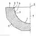
FIG. 1 shows a section through a socket insert 1 made from a ceramic material. The central point 2 of the spherical indentation 3 lies on the axis of symmetry 4 of the spherical indentation. A particular form of wear in the case of hard-on-hard material pairings occurs in the region of the so-called run-in edge 5. This is located at the transition between the spherical indentation 3 of the socket insert 1 and the run-in zone 6. The run-in zone 6 ends with a circular arc 7 tangentially at the transition 8 on the end face 9 of the socket insert 1. As a result of subluxation and also micro-separation of the spherical head that occurs, high loads result, in the region of the run-in edge 5, both for the socket insert 1 and for the spherical head, which is not shown here. Consequently, locally increased wear occurs which, depending on the material, leads to increased abrasion or to a visible increase in surface roughness. The increase in the surface roughness that is referred to as stripe wear is just as undesirable as the metallic abrasion that otherwise occurs to an increased extent.
The increased wear that occurs in the region of the run-in edge 5 is to be attributed to the action of high surface pressure (concentrated load) and also the discontinuous force characteristic during the sliding movement of the spherical head in the region of the run-in zone 6.
The underlying object of the invention is to avoid the wear in the region of the run-in zone or at least reduce it to a great extent.
In order to achieve this object, in accordance with the invention it is proposed that the geometry of the run-in zone 6, between the end point 12 of the circular arc 7 and the run-in edge 5 in the spherical indentation 3 be realized as a curve 14, the function of which can be continuously differentiated twice at every point.
In FIG. 2 the run-in zone 6 in the socket insert 1 is shown as a cutaway portion on an enlarged scale in comparison with that of FIG. 1. The circular arc 7 with the central point 10 at the start of the run-in zone 6 has a radius 11 with the length RE. The circular arc 7 ends at the point 12 where the curve 14 in accordance with the invention of the run-in zone 6 follows on. The transition of the curve 14 to the circular arc of the spherical indentation 3 lies in the run-in edge 5, with the circular arc of the spherical indentation 3 having a radius 13 with the length RK. The point A, the start 12 of the circular arc 7, and the point B, the run-in edge 5, are the points of the curve 14 at which its curvature coincides with the curvature of the respective curve following on, the circular arc 7 and the circular arc 3 of the spherical indentation respectively.
This curve 14 of the run-in zone 6 has at its two end points A and B the respective curvature of the curve that follows on. At the end point A, the formula of the curve 14 thus reads f″A(x,y)=1/RE and at the end point B f″B(x,y)=1/RK.
In this way, the curvature characteristic of the curve 14 on which the spherical head moves between the spherical indentation 3 and the run-in radius 7 is continuous. This results in the charadteristic both of the contact force and also of the surface pressure likewise being continuous. The spherical head rolls off in the socket insert. Sliding movements are avoided.
In order to describe the curve 14 mathematically, various functions are conceivable. For example, at this point the sinusoidal curve shapes known from cam gears or even polynomial forms can be mentioned.
Claims
1-4. (canceled)
5. A socket insert of a hip joint prosthesis,
wherein said socket insert has a spherical-identation-sahped recess in which a spherical. head of a femur is mounted;
wherein the spherical indentation comprises a run-in zone which ends on one side with a circular arc tangentially in an end face of the socket insert and extends on another side as far as the run-in edge;
wherein between a start of the circular arc with a radius of the length (RE) and the run-in edge of the spherical indentation with the radius of the length (RK) the run-in zone forms a curve, the function of which is continuously differentiated twice at every point.
6. A socket insert according to claim 5, wherein the curve at its respective end points (A), the end point of the circular arc, and (B), the run-in edge, has the same curvature as the curves following on from it, the circular arc and the spherical indentation, respectively.
7. A socket insert according to claim 5, wherein the shape of the curve is sinusoidal or has a polynomial form.
8. A socket insert according to claim 6, wherein the shape of the curve is sinusoidal or has a polynomial form.
9. A socket insert according to claim 5, wherein the formula of the curve at its end point (A), the start of the circular arc, reads f″A(x,y)=1/RE and at its end point (B), the run-in edge and the start of the circular arc of the spherical indentation, reads f″B(x,y)=1/RK.
10. A socket insert according to claim 6, wherein the formula of the curve at its end point (A), the start of the circular arc, reads f″A(x,y)=1/RE and at its end point (B), the run-in edge and the start of the circular arc of the spherical indentation, reads f″B(x,y)=1/RK.
11. A socket insert according to claim 7, wherein the formula of the curve at its end point (A), the start of the circular arc, reads f″A(x,y)=1/RE and at its end point (B), the run-in edge and the start of the circular arc of the spherical indentation, reads f″B(x,y)=1/RK.
12. A socket insert according to claim 8, wherein the formula of the curve at its end point (A), the start of the circular arc, reads f″A(x,y)=1/RE and at its end point (B), the run-in edge and the start of the circular arc of the spherical indentation, reads f″B(x,y)=1/RK.
Images & Drawings included:
Sources:
- United States Patent and Trademark Office - verify current appl. status at the USPTO↗
Recent applications in this class:
- » 20250195232 2025-06-19
RESURFACING CUP FOR ACETABULUM HEMIARTHROPLASTY OF THE HIP JOINT - » 20250195231 2025-06-19
IMPLANT COMPONENTS AND METHODS - » 20250152367 2025-05-15
HIP JOINT DEVICE AND METHOD - » 20250143886 2025-05-08
Cemented Sheath For Joint Implant - » 20250120817 2025-04-17
ARTIFICIAL HIP JOINT - » 20250090331 2025-03-20
ACETABULAR CUP AND HIP JOINT PROSTHESIS ASSEMBLY - » 20250082475 2025-03-13
DUAL MOBILITY ACETABULAR COMPONENT - » 20250032263 2025-01-30
ARTIFICIAL ACETABULAR CUP AND MANUFACTURING METHOD THEREOF - » 20250017736 2025-01-16
APPARATUS AND METHOD FOR INSTALLING AN ACETABULAR LINER ON AN ACETABULAR CUP - » 20250017735 2025-01-16
NON-IMPINGING DUAL MOBILITY HIP PROSTHESIS
Recent applications for this Assignee:
- » 20210384115 2021-12-09
Module with connection lugs for supply lines - » 20210071697 2021-03-11
Connection arrangement of two components - » 20200030888 2020-01-30
Tool system - » 20190366444 2019-12-05
Tool system - » 20190091031 2019-03-28
Knee endoprosthesis for replacing at least parts of the knee joint - » 20190006578 2019-01-03
Production of lead-free piezoceramics in aqueous surroundings - » 20190001419 2019-01-03
Carrier tool, cutting insert, and clamping element - » 20170362131 2017-12-21
α/β-sialon having improved sintering activity and high edge strength - » 20170348464 2017-12-07
COMPONENTS FOR FUSING VERTEBRAL BODIES - » 20170341154 2017-11-30
Cutting insert geometry