Method of diagnosing the presence of an exhaust after-treatment component and a use of the method for vehicle on-board diagnosis
US20100162691A1
2010-07-01
11/909,578
2005-04-14
✅ Patent granted
US 7,752,901 B1
2010-07-13
WO; PCT/SE2005/000545; 20050414
WO; WO2006/110071; 20061019
Eric S McCall
2026-09-15
Abstract:
In a method for diagnosing the presence of an internal combustion engine exhaust aftertreatment component on a vehicle, the exhaust temperature is measured downstream the aftertreatment component continuously over a time period to provide a first temperature signal with fluctuating amplitude. The temperature signal is modified to provide a second modified temperature signal. The first and second temperature signals are compared to detect any significant difference between the signals.
Assignee:
- VOLVO LASTVAGNAR AB 445 🇸🇪 gOTEBORG, Sweden
Interested in similar patents?
Get notified when new applications in this technology area are published.
Classification:
F01N11/002 » CPC main
Monitoring or diagnostic devices for exhaust-gas treatment apparatus, e.g. for catalytic activity the diagnostic devices measuring or estimating temperature or pressure in, or downstream of the exhaust apparatus
F01N13/009 » CPC further
Exhaust or silencing apparatus characterised by constructional features ; Exhaust or silencing apparatus, or parts thereof, having pertinent characteristics not provided for in, or of interest apart from, groups - , , having two or more separate purifying devices arranged in series
F01N13/0093 » CPC further
Exhaust or silencing apparatus characterised by constructional features ; Exhaust or silencing apparatus, or parts thereof, having pertinent characteristics not provided for in, or of interest apart from, groups - , , having two or more separate purifying devices arranged in series the purifying devices are of the same type
F01N3/021 » CPC further
Exhaust or silencing apparatus having means for purifying, rendering innocuous, or otherwise treating exhaust for cooling, or for removing solid constituents of, exhaust by means of filters
F01N3/2006 » CPC further
Exhaust or silencing apparatus having means for purifying, rendering innocuous, or otherwise treating exhaust for rendering innocuous by thermal or catalytic conversion of noxious components of exhaust characterised by methods of operation; Control specially adapted for catalytic conversion ; Methods of operation or control of catalytic converters Periodically heating or cooling catalytic reactors, e.g. at cold starting or overheating
F01N2550/24 » CPC further
Monitoring or diagnosing the deterioration of exhaust systems Determining the presence or absence of an exhaust treating device
Y02A50/20 » CPC further
in human health protection, e.g. against extreme weather Air quality improvement or preservation, e.g. vehicle emission control or emission reduction by using catalytic converters
Y02T10/40 » CPC further
Road transport of goods or passengers; Internal combustion engine [ICE] based vehicles Engine management systems
Y02T10/40 » CPC further
Road transport of goods or passengers; Internal combustion engine [ICE] based vehicles Engine management systems
F01N3/10 IPC
Exhaust or silencing apparatus having means for purifying, rendering innocuous, or otherwise treating exhaust for rendering innocuous by thermal or catalytic conversion of noxious components of exhaust
G01M15/10 IPC
Testing of engines; Testing internal-combustion engines by monitoring exhaust gases or combustion flame
Description
BACKGROUND AND SUMMARY
The present invention relates to a method for diagnosing the presence of an internal combustion engine exhaust aftertreatment component on a vehicle.
In recent years, statutory requirements pertaining to emissions from Diesel engines have been tightened up. For example, new legislation regarding on-board diagnosis requires that the presence of a so-called pre-catalyst is determined.
It is desirable to provide a method to determine whether an aftertreatment component in an aftertreatment system is present or not.
BRIEF DESCRIPTION OF THE DRAWINGS
The invention will be described in greater detail below with reference to embodiments shown in the accompanying drawings.
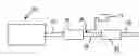
In FIG. 1, an internal combustion engine with an exhaust aftertreatment system for utilizing the invention is illustrated diagrammatically.
FIG. 2 is a first graph illustrating temperature variations in the exhaust aftertreatment system shown in FIG. 1.
FIG. 3 is a second graph illustrating temperature variations in the exhaust aftertreatment system.
DETAILED DESCRIPTION
FIG. 1 shows a general configuration of an exhaust aftertreatment system for an internal combustion engine 10, including a first exhaust pipe segment 11 leading exhausts from the engine to a pre-catalyst 12. The pre-catalyst is connected to a selective catalyst reactor 13 via a second exhaust pipe segment 14. A third exhaust pipe segment 15 leads exhausts from the reactor 13 to the atmosphere.
A temperature sensor 16 is positioned at the second exhaust pipe segment 14 for measuring the temperature of the exhaust stream exiting the pre-catalyst 12. The temperature is measured continuously over a time period to provide a first temperature signal with fluctuating amplitude that is recorded by a data processor 17. A typical temperature/time graph is shown in FIG. 2. Due to the fact that the pre-catalyst 12 comprises a thermic mass, i.e. the reactor monolith, the exhaust temperature variations are filtered when the exhaust stream passes through the pre-catalyst.
An example of a typical un-filtered temperature graph is shown in FIG. 3, showing temperature variations with higher frequency than in FIG. 2. If the pre-catalyst 12 is not present in the exhaust aftertreatment system, the temperature sensor 16 will provide a signal with a similar signature as the graph shown in FIG. 3.
The recorded temperature signal is modified by the data processor 17 to provide a second modified temperature signal. The first and second temperature signals are compared to detect any significant difference between the signals. The modified signal may be obtained by any type of analysis of the temperature signal that is based on signal frequency or signal derivative. For example, a low-pass filter in the data processor 17 may be used for removing signals with frequency over a certain level. By integrating the unfiltered and filtered temperature signals and calculating the difference between the two, it is possible to determine whether the catalyst reactor monolith is present. A large difference is the result when the monolith is missing and a small difference when the monolith is present.
If the pre-catalyst is not present in the aftertreatment system, the first signal will have a signature similar to the graph of FIG. 3. When the signal has been modified by means of the data processor 17, the resulting second signal will have a signature similar to the graph of FIG. 2. Thus, the comparison between the two signals positively indicates that no catalyst reactor monolith is present upstream the temperature sensor 16.
If the pre-catalyst is present, both first and second signals will have signatures similar to the graph of FIG. 2. Thus, the comparison between the two signals positively indicates that a thermic mass, e.g. a catalyst reactor monolith is present in the aftertreatment system upstream the temperature sensor 16.
The invention is not to be regarded as being limited to the illustrative embodiments described above, but a number of variants and modifications are possible within the scope of the following patent claims. For example, the method according to the invention can be applied to any type of aftertreatment component, as long as it comprises a thermic mass. The aftertreatment component may for example be a particle filter. It is preferable that the aftertreatment component being diagnosed with the method according to the invention has a larger thermic mass than any other aftertreatment component positioned upstream. The comparison of the two temperature signals can be performed in many different ways, both analogical and digital.
Claims
1. A method of diagnosing the presence of an internal combustion engine exhaust aftertreatment component on a vehicle using a single temperature signal source, wherin the aftertreatment component component comprises a thermic mass, comprising
measuring the exhaust temperature downstream of the aftertreatment component continuously over a time period to provide a first temperature signal with fluctuating amplitude,
modifying the temperature signal to provide a second modified temperature signal using a temperature signal analysis based on signal frequency or signal derivative, and
comparing the first temperature signal and the second modified temperature signal to determine whether there is a difference between the signals.
2. A method according to claim 1, wherein the aftertreatment component is a catalyst reactor.
3. A method according to claim 2, wherein the aftertreatment component is positioned as a first aftertreatment component downstream of the engine.
4. A method according to claim 3, wherein modifying comprises filtering the temperature signal.
5. A method according to claim 4, wherein the first temperature signal is unfiltered, the method comprising integrating both the first temperature signal and the second modified filtered temperature signal and calculating a difference between the two integrals.
6. Use of a method according to claim 1 for on-board diagnosis of presence of a catalyst reactor in an exhaust aftertreatment system of a vehicle.
7. A method according to claim 1, wherein the aftertreatment component is positioned as a first aftertreatment component downstream of the engine.
8. A method according to claim 7, wherein modifying comprises filtering the temperature signal.
9. A method according to claim 8, wherein the first temperature signal is unfiltered, the method comprising integrating both the first temperature signal and the second modified temperature signal and calculating a difference between the two integrals.
10. A method according to claim 2, wherein modifying comprises filtering the temperature signal.
11. A method according to claim 10, wherein the first temperature signal is unfiltered, the method comprising integrating both the first temperature signal and the second modified temperature signal and calculating a difference between the two integrals.
Images & Drawings included:

Sources:
- United States Patent and Trademark Office - verify current appl. status at the USPTO↗
Recent applications in this class:
- » 20250264049 2025-08-21
METHOD FOR DETECTING EXHAUST BACKFLOW IN AN INTERNAL COMBUSTION ENGINE - » 20250092813 2025-03-20
METHOD FOR ASCERTAINING AN OPERATING STATE OF A BURNER - » 20250043711 2025-02-06
DIESEL ENGINE AFTERTREATMENT SYSTEM - » 20240392716 2024-11-28
COMPUTER-IMPLEMENTED METHOD FOR DETECTING A FAULT IN A SELECTIVE CATALYTIC REDUCER ASSEMBLY - » 20240318585 2024-09-26
SYSTEMS AND METHODS FOR DIAGNOSING COMPONENT FAILURE - » 20240295185 2024-09-05
SYSTEMS AND METHODS FOR EXHAUST AFTERTREATMENT SENSOR OFFSET DETECTION AND DIAGNOSIS - » 20240254909 2024-08-01
VEHICLE EMISSIONS MANAGEMENT - » 20240191646 2024-06-13
METHOD AND DEVICE FOR DIAGNOSING AN AIR SUPPLY OF AN INTERNAL COMBUSTION ENGINE - » 20240183303 2024-06-06
System and method for monitoring an oxidation catalyst - » 20240093625 2024-03-21
Method for operating a particle filter taking the ash quantity into consideration
Recent applications for this Assignee:
- » 20160369725 2016-12-22
Controller and control method for engines - » 20160288662 2016-10-06
Charge/discharge system - » 20160003121 2016-01-07
METHOD FOR CONTROLLING THE REDUCTANT BUFFER LEVEL IN AN EXHAUST GAS AFTERTREATMENT DEVICE - » 20160001777 2016-01-07
Method and arrangement for entering a preceding vehicle autonomous following mode - » 20150367844 2015-12-24
Method and arrangement for vehicle stabilization - » 20150314694 2015-11-05
Electrical apparatus and method for charging a battery - » 20150308565 2015-10-29
Arrangement and method for estimating the input torque of a dual-clutch transmission - » 20150308488 2015-10-29
Retaining ring retention system and method - » 20150307040 2015-10-29
Arrangement for displaying information in a vehicle - » 20150306972 2015-10-29
Electrical apparatus and method for powering an electrical machine