Longitudinal bulging seal for spray gun
US20100163771A1
2010-07-01
12/600,685
2008-05-30
✅ Patent granted
US 8,272,621 B2
2012-09-25
WO; PCT/US2008/065220; 20080530
WO; WO2008/156990; 20081224
John Bastianelli
2029-03-24
Abstract:
The seal (10) for a spray gun (20) is tubular in form and molded from an elastomer. The seal is placed in compression between two generally parallel surfaces (12) so as to seal out the fluid (such as paint) from the rod (14). As the trigger (16) is pulled and the rod (14) moved rearward, the seal (10) bulges to accomodate the travel without exposing the rod (14) to the fluid.
Inventors:
- Eric J. Finstad 23 🇺🇸 Rogers, MN, United States
- Thomas E. Pauly 8 🇺🇸 Zimmerman, MN, United States
Assignee:
- Graco Minnesota Inc. 479 🇺🇸 Minneapolis, MN, United States
Interested in similar patents?
Get notified when new applications in this technology area are published.
Classification:
B05B1/3046 » CPC main
Nozzles, spray heads or other outlets, with or without auxiliary devices such as valves, heating means designed to control volume of flow, e.g. with adjustable passages the control being effected by relative coaxial longitudinal movement of the controlling element and the spray head the controlling element being a lift valve the valve element, e.g. a needle, co-operating with a valve seat located downstream of the valve element and its actuating means, generally in the proximity of the outlet orifice
B05B9/01 » CPC further
Spraying apparatus for discharge of liquids or other fluent material, without essentially mixing with gas or vapour Spray pistols, discharge devices
B05B1/30 IPC
Nozzles, spray heads or other outlets, with or without auxiliary devices such as valves, heating means designed to control volume of flow, e.g. with adjustable passages
F16K31/44 IPC
Operating means Actuating devices; ; Releasing devices Mechanical actuating means
Description
TECHNICAL FIELD
This application claims the benefit of U.S. Application Ser. No. 60/943,951, filed on Jun. 14, 2007, the contents of which are hereby incorporated by reference.
BACKGROUND ART
Traditional seals in spray guns (particularly airless spray guns) have been of the type where the rod travels into and out of the fluid being sealed. This often results in fluid drying on the rod with the dried fluid abrading the seal resulting in premature seal failure and leakage.
DISCLOSURE OF THE INVENTION
The seal of the instant invention is tubular in form and molded from an elastomer. In the preferred embodiment, the seal is actually molded in two parts—inner and outer cylindrical tubes which are slip fit together. In the preferred embodiment, the outer tube is formed from a fluoroelastomer such as those sold under the trademark VITON while the inner tube is molded from a polyethylene elastomer. The seal is placed in compression between two generally parallel surfaces so as to seal out the fluid (such as paint) from the rod. As the trigger is pulled and the rod moved rearward (relative to the front/spraying end of the gun), the seal bulges to accommodate the travel.
These and other objects and advantages of the invention will appear more fully from the following description made in conjunction with the accompanying drawings wherein like reference characters refer to the same or similar parts throughout the several views.
BRIEF DESCRIPTION OF DRAWINGS
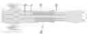
FIG. 1 is a cross-section of the front end of a spray gun utilizing the instant invention.
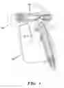
FIG. 2 is a cross-section of the needle assembly utilizing the instant invention.
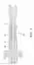
FIG. 3 is a simplified cross-section of the seal in the closed position.
FIG. 4 is a simplified cross-section of the seal in the open position.
BEST MODE FOR CARRYING OUT THE INVENTION
The seal of 10 the instant invention is tubular in form and molded from an elastomer. The needle assembly 16 is located in spray gun 20. In the preferred embodiment, the seal 10 is actually molded in two parts—inner 10a and outer 10b cylindrical tubes which are slip fit together. In the preferred embodiment, the outer tube 10b is formed from a fluoroelastomer such as those sold under the trademark VITON while the inner tube 10a is molded from a polyethylene elastomer.
The seal 10 is placed in compression between two generally parallel surfaces 12 so as to seal out the fluid (such as paint) from the rod 14. As the trigger 16 is pulled and the rod 14 moved rearward (relative to the front/spraying end 18 of the gun 20), the seal 10 bulges to accommodate the travel as shown in FIG. 4. The rear end of needle 14 is threaded (or otherwise attached such as by welding or adhesive bonding) into needle actuator 22 which in turn is slideably located in seal housing 24.
It is contemplated that various changes and modifications may be made to the seal assembly without departing from the spirit and scope of the invention as defined by the following claims.
Claims
1. A needle assembly for use in a spray gun comprising:
a needle having a reduced dimension seal locating rod and an annular rearward facing seal retention portion;
a tubular seal located over at least part of said seal locating rod; and
a seal housing having an annular forward facing seal retention portion, said tubular seal being located between said annular facing seal retention portions.
2. The needle assembly of claim 1 wherein said seal comprises an inner tube and an outer tube.
3. The needle assembly of claim 2 wherein said inner tube comprises a polyethylene elastomer.
4. The needle assembly of claim 2 wherein said outer tube comprises a fluoroelastomer.
5. The needle assembly of claim 1 further comprising a needle actuator attached to said rod.
Images & Drawings included:


Sources:
- United States Patent and Trademark Office - verify current appl. status at the USPTO↗
Recent applications in this class:
- » 20250281938 2025-09-11
SPIT REDUCTION FOR FLUID APPLICATORS - » 20250083158 2025-03-13
HANDHELD LIQUID SPRAY GUN - » 20240408626 2024-12-12
MULTIPART MATERIAL NEEDLE FOR A PAINT SPRAY GUN, FRONT NEEDLE OF A MATERIAL NEEDLE, PAINT SPRAY GUN, AND METHOD FOR EXCHANGING A FRONT NEEDLE - » 20240390922 2024-11-28
PAINT SPRAY GUN WITH TWO-PART MATERIAL NEEDLE, MATERIAL NEEDLE, FRONT NEEDLE OF A MATERIAL NEEDLE, AND METHOD FOR EXCHANGING A FRONT NEEDLE - » 20240253068 2024-08-01
ADHESIVE SPRAY NOZZLE AND METHODS OF USING THE SAME - » 20230330688 2023-10-19
PAINT NOZZLE MODULE FOR A PAINT SPRAYING DEVICE - » 20230285996 2023-09-14
Valve tappet rod - » 20230234081 2023-07-27
FLUID CONTROL STRUCTURE OF DISPENSING APPARATUS - » 20220258186 2022-08-18
Spray gun comprising a trigger coupling member having a deployed configuration - » 20220250099 2022-08-11
JETTING NEEDLE INTEGRATION WITH FLUID JETTING VALVE AND METHODS THEREOF
Recent applications for this Assignee:
- » 20250101975 2025-03-27
PUMP ROD AND DRIVING LINK WITH SIDE-LOAD REDUCING CONFIGURATION - » 20240383119 2024-11-21
POWER TOOL ATTACHMENT - » 20240375133 2024-11-14
FLUID SPRAYER WITH COVERED BATTERY - » 20240316577 2024-09-26
Fluid sprayer - » 20240309595 2024-09-19
ROAD TAPING MACHINE - » 20240293832 2024-09-05
Fluid sprayer - » 20240226943 2024-07-11
Fluid sprayer with battery power - » 20240219937 2024-07-04
PAINT SPRAYER DISTRIBUTED CONTROL AND OUTPUT VOLUME MONITORING ARCHITECTURES - » 20240213720 2024-06-27
Heated hose electrical connectors - » 20240207875 2024-06-27
Mix chamber for a plural component sprayer