Electrophoretic display
US20100172015A1
2010-07-08
12/651,617
2010-01-04
✅ Patent granted
US 8,107,159 B2
2012-01-31
-
-
Ricky Mack | Brandi Thomas
2030-01-04
Abstract:
An electronic device includes a first substrate made of thin plastic sheet; a second substrate made of thin plastic sheet opposing the first substrate; a chamber formed between portions of the first and second substrates; and a sealing structure configured to seal the chamber at the interface between the first and second substrates, wherein the sealing structure surrounds the chamber and comprises a recess formed in one of the substrates and a protrusion formed on the other of the substrates, the protrusion engaging the recess.
Assignee:
- JOHNSON ELECTRIC S.A. 98 🇨🇭 La Chaux-de-Fonds, Switzerland
Interested in similar patents?
Get notified when new applications in this technology area are published.
Classification:
G09F9/30 » CPC main
Indicating arrangements for variable information in which the information is built-up on a support by selection or combination of individual elements in which the desired character or characters are formed by combining individual elements
B23K20/10 » CPC further
Non-electric welding by applying impact or other pressure, with or without the application of heat, e.g. cladding or plating making use of vibrations, e.g. ultrasonic welding
G02F1/16755 » CPC further
Devices or arrangements for the control of the intensity, colour, phase, polarisation or direction of light arriving from an independent light source, e.g. switching, gating or modulating; Non-linear optics for the control of the intensity, phase, polarisation or colour based on translational movement of particles in a fluid under the influence of an applied field; Constructional details Substrates
G02F1/1679 » CPC further
Devices or arrangements for the control of the intensity, colour, phase, polarisation or direction of light arriving from an independent light source, e.g. switching, gating or modulating; Non-linear optics for the control of the intensity, phase, polarisation or colour based on translational movement of particles in a fluid under the influence of an applied field; Constructional details Gaskets; Spacers; Sealing of cells; Filling or closing of cells
G09F9/372 » CPC further
Indicating arrangements for variable information in which the information is built-up on a support by selection or combination of individual elements in which the desired character or characters are formed by combining individual elements being movable elements the positions of the elements being controlled by the application of an electric field
B23K2101/40 » CPC further
Articles made by soldering, welding or cutting; Electric or electronic devices Semiconductor devices
B29C65/08 » CPC further
Joining of preformed parts ; Apparatus therefor by heating, with or without pressure using ultrasonic vibrations
B29C65/48 » CPC further
Joining of preformed parts ; Apparatus therefor using adhesives, i.e. using supplementary joining material; solvent bonding
B29K2023/06 » CPC further
Use of polyalkenes or derivatives thereof as moulding material; Polymers of ethylene PE, i.e. polyethylene
B29K2023/12 » CPC further
Use of polyalkenes or derivatives thereof as moulding material; Polymers of propylene PP, i.e. polypropylene
B29K2027/06 » CPC further
Use of polyvinylhalogenides or derivatives thereof as moulding material PVC, i.e. polyvinylchloride
B29K2067/00 » CPC further
Use of polyesters or derivatives thereof , as moulding material
B29K2069/00 » CPC further
Use of PC, i.e. polycarbonates or derivatives thereof , as moulding material
B29K2079/08 » CPC further
PI, i.e. polyimides or derivatives thereof
B29K2081/06 » CPC further
Use of polymers having sulfur, with or without nitrogen, oxygen or carbon only, in the main chain, as moulding material PSU, i.e. polysulfones; PES, i.e. polyethersulfones or derivatives thereof
B29K2995/0025 » CPC further
Properties of moulding materials, reinforcements, fillers, preformed parts or moulds having particular optical properties, e.g. fluorescent or phosphorescent Opaque
B29K2995/0026 » CPC further
Properties of moulding materials, reinforcements, fillers, preformed parts or moulds having particular optical properties, e.g. fluorescent or phosphorescent Transparent
B29L2031/3061 » CPC further
Other particular articles; Vehicles, e.g. ships or aircraft, or body parts thereof; Cars Number plates
G02F1/1339 » CPC further
Devices or arrangements for the control of the intensity, colour, phase, polarisation or direction of light arriving from an independent light source, e.g. switching, gating or modulating; Non-linear optics for the control of the intensity, phase, polarisation or colour based on liquid crystals, e.g. single liquid crystal display cells; Constructional arrangements; Operation of liquid crystal cells; Circuit arrangements; Constructional arrangements; Manufacturing methods Gaskets; Spacers; Sealing of cells
G02F1/1341 » CPC further
Devices or arrangements for the control of the intensity, colour, phase, polarisation or direction of light arriving from an independent light source, e.g. switching, gating or modulating; Non-linear optics for the control of the intensity, phase, polarisation or colour based on liquid crystals, e.g. single liquid crystal display cells; Constructional arrangements; Operation of liquid crystal cells; Circuit arrangements; Constructional arrangements; Manufacturing methods Filling or closing of cells
G02F1/16757 » CPC further
Devices or arrangements for the control of the intensity, colour, phase, polarisation or direction of light arriving from an independent light source, e.g. switching, gating or modulating; Non-linear optics for the control of the intensity, phase, polarisation or colour based on translational movement of particles in a fluid under the influence of an applied field; Constructional details Microcapsules
G02F2202/28 » CPC further
Materials and properties Adhesive materials or arrangements
G02F1/167 » CPC further
Devices or arrangements for the control of the intensity, colour, phase, polarisation or direction of light arriving from an independent light source, e.g. switching, gating or modulating; Non-linear optics for the control of the intensity, phase, polarisation or colour based on translational movement of particles in a fluid under the influence of an applied field characterised by the electro-optical or magneto-optical effect by electrophoresis
G02B26/00 IPC
Optical devices or arrangements for the control of light using movable or deformable optical elements
G02B26/08 IPC
Optical devices or arrangements for the control of light using movable or deformable optical elements for controlling the direction of light
G02F1/29 IPC
Devices or arrangements for the control of the intensity, colour, phase, polarisation or direction of light arriving from an independent light source, e.g. switching, gating or modulating; Non-linear optics for the control of the position or the direction of light beams, i.e. deflection
Description
CROSS REFERENCE TO RELATED APPLICATIONS
This non-provisional patent application claims priority under 35 U.S.C. §119(a) from Patent Application No. 200910104842.0 filed in The People's Republic of China on Jan. 7, 2009.
FIELD OF THE INVENTION
This invention relates to an electronic device and in particular, to a sealing structure of an electrophoretic display.
BACKGROUND OF THE INVENTION
An electrophoretic display (EPD) is a non-emissive device based on the electrophoresis phenomenon of charged pigment particles suspended in a dielectric solvent. The display usually comprises two substrates with electrodes placed opposing each other and separated by spacers. An electrophoretic fluid composed of a colored solvent with charged pigment particles dispersed therein is enclosed between the two electrodes. One of the electrodes on the viewing side is usually transparent. When a voltage difference is applied across the two electrodes, the pigment particles migrate to one side causing either the color of the pigment particles or the color of the solvent to be seen from the viewing side.
Known displays use an intermediate adhesive layer disposed between peripheries of the two substrates for sealing the electrophoretic fluid chambers. However, the adhesive layer is subject to aging and hardens losing its flexibility and may peel off from the substrates after being used for a long period, especially when used in environment with high temperature or subject to direct sunlight.
SUMMARY OF THE INVENTION
Hence there is a desire for an improved EPD which can solve the above mentioned problem.
Accordingly, in one aspect thereof, the present invention provides an electronic device comprising: a first substrate made of thin plastic sheet; a second substrate made of thin plastic sheet opposing the first substrate; a sealed chamber formed between portions of the first and second substrates; and a sealing structure configured to seal the chamber being formed at the interface between the first and second substrates, wherein the sealing structure surrounds the chamber and comprises a recess formed in one of the substrates and a protrusion formed on the other of the substrates, the protrusion being engaged in the recess.
Preferably, the electronic device further comprises two opposing electrodes attached to inner surfaces of the first and second substrates respectively, the chamber being formed between the two electrodes.
Preferably, the electronic device is an electrophoretic display, a plurality of microcapsules is received in the chamber and sandwiched between the electrodes, one of the substrates and a corresponding electrode attached thereon being made of transparent material.
Preferably, the microcapsules are bonded to each other by a binder.
Preferably, each of the microcapsules contains a dispersion comprising electrophoretic particles dispersed in a dispersion medium.
Preferably, the protrusion comprises a rib, and the recess comprises a groove.
Preferably, the rib and groove both have continuous configurations to thereby completely surround the chamber.
Preferably, the rib is comprised of discontinuous sections, gaps between the sections are sealed with adhesive layer.
Preferably, the sealing structure further comprises an adhesive layer spread at the interface.
Preferably, there are at least one additional spaced sealing structure arranged in the radial direction of the chamber to thereby provide multiple seals for the chamber.
Preferably, the protrusion comprises a plurality of bumps and the recess comprises a plurality of cavities.
Preferably, the protrusion is a press fit in the recess.
Preferably, the protrusion is secured in the recess by ultrasonic welding.
BRIEF DESCRIPTION OF THE DRAWINGS
A preferred embodiment of the invention will now be described, by way of example only, with reference to the single figure of the accompanying drawings, in which:
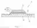
FIG. 1 is a cross sectional view of an electrophoretic display in accordance with the preferred embodiment of the present invention.
Dimensions of components and features shown in the figure are generally chosen for convenience and clarity of presentation and are not necessarily shown to scale.
DETAILED DESCRIPTION OF THE PREFERRED EMBODIMENTS
The technical problem to be solved, the technical solution and the beneficial effects of the present invention are best understood from the following detailed description with reference to the accompanying figure and embodiments. It is to be understood that, the specific embodiments described here are merely examples to explain the invention and are not intended to limit the present invention.
Referring to FIG. 1, an electrophoretic display 10 according to the preferred embodiment of the present invention comprises a first substrate 20, a second substrate 30 opposing the first substrate 20, and a display unit 40 disposed between the first and second substrates 20, 30. The first and second substrates 20, 30 may be made of thin plastic sheet.
The first substrate 20 is located close the viewing side and therefore made of transparent material. Preferably, the first substrate 20 is made of PET, PEN, PES, PC, or PE etc. A portion of the first substrate 20 corresponding to the display unit 40 is spaced from the second substrate 30 to thereby form a chamber therebetween. The display unit 40 is disposed in the chamber. The second substrate 30 may be made of transparent material or nontransparent material. Thus, in addition to PET, PEN, PES, PC, or PE, the second substrate 30 may be made of PI, PVC, PS or PP etc.
At least one sealing structure is formed at the interface of the first and second substrates 20, 30, surrounding the display unit 40. The sealing structure surrounds the chamber and comprises a recess formed at one of the substrates and a protrusion formed from the other of the substrates, the protrusion is secured in the recess. As shown in FIG. 1, the sealing structure may comprise a groove 32 formed in a surface of the second substrate 30 facing the first substrate 20, a rib 22 formed on a surface of the first substrate 20 facing the second substrate 30. The rib 22 is secured in the groove 32, to thereby form the sealing structure.
A method to form the sealing structure will now be described in detail. A rib 22 is formed at the periphery of a surface of the first substrate 20 facing the second substrate 30 by punching, pressing, rolling or other ways. The periphery of the first substrate 20 is engaged with the periphery of the second substrate 30 using a hot press. The periphery of the second substrate 30 corresponding to the rib 22 of the first substrate is deformed to form a groove 32. The rib 22 is pressed into the groove 32.
Alternatively, both the rib 22 and the groove 32 may be pre-formed before engagement. In another method the rib and groove may be formed together at the same time in a single step, whereby when the first substrate is overlaying the second substrate, a ridge is pressed from one substrate into the other to form the groove and to join the two substrates together. Additional mechanical connection means may be used to fix the rib 22 in the groove 32. For example, ultrasonic welding may be used to fix the rib 22 in the groove 32.
Alternatively, the positions of the rib 22 and groove 32 may be exchanged.
Preferably, an additional adhesive layer may be disposed at the interface between the first and second substrates 20, 30 before the rib 22 is fixed in the groove 32.
The rib 22 and groove 32 may have a continuous ring configuration, completely surrounding the display unit 40. Alternatively, the rib 22 and groove 32 may be composed of several discontinuous sections, mostly but not completely surrounding the display unit 40. An adhesive layer may be used to seal any gaps between adjacent sections.
The protrusion 22 of the sealing structure is not limited to a rib. For example, the protrusion 22 may comprises a plurality of discrete bumps, and the recess 32 may comprise a plurality of discrete holes or cavities corresponding to the bumps.
The display unit 40 comprises a first electrode 42 disposed at the inner surface of the first substrate 20, a second electrode 44 disposed at the inner surface of the second substrate 30, and an electrophoretic layer 46 disposed between the first and second electrodes 42, 44.
The electrodes 42, 44 may be made of ITO (Indium-Tin Oxide). The first electrode 42 is made of transparent material.
The electrophoretic layer 46 comprises a plurality of microcapsules. The microcapsules are sandwiched between the electrodes 42, 44 and bonded to each other by a binder. In each of the microcapsules is sealed a dispersion comprising electrophoretic particles dispersed in a dispersion medium in advance by a micro capsulation technique. When a voltage difference is imposed between the two electrodes 42, 44, the particles migrate closer one of the electrodes 42, 44 causing either the color of the particles or the color of the dispersion medium to be seen from the viewing side.
Alternatively, each microcapsule may enclose therein two kinds of charged particles of different colors, for example, one kind of particle is made of TiO2 in white and the other kind of particle is made of black carbon. When a voltage difference is applied between the two electrodes 42, 44, the black particles migrate closer the first electrode 42 causing the color of the black particles to be seen from the viewing side.
Alternatively, the sealing structure of the present invention may also be used to seal a chamber formed between two thin plastic sheets of other electric devices.
In the description and claims of the present application, each of the verbs “comprise”, “include”, “contain” and “have”, and variations thereof, are used in an inclusive sense, to specify the presence of the stated item but not to exclude the presence of additional items.
Although the invention is described with reference to one or more preferred embodiments, it should be appreciated by those skilled in the art that various modifications are possible. Therefore, the scope of the invention is to be determined by reference to the claims that follow.
Claims
1. An electronic device comprising:
a first substrate made of thin plastic sheet;
a second substrate made of thin plastic sheet opposing the first substrate;
a chamber formed between portions of the first and second substrates; and
a sealing structure arranged to seal the chamber being formed at the interface between the first and second substrates, wherein the sealing structure surrounds the chamber and comprises a recess formed at one of the substrates and a protrusion formed from the other of the substrates, the protrusion being engaged in the recess.
2. The electronic device of claim 1, wherein the electronic device further comprises two opposing electrodes attached to inner surfaces of the first and second substrates respectively, the chamber being formed between the two electrodes.
3. The electronic device of claim 2, wherein the electronic device is an electrophoretic display, a plurality of microcapsules is received in the chamber and sandwiched between the electrodes, one of the substrates and a corresponding electrode attached thereon being made of transparent material.
4. The electronic device of claim 3, wherein the microcapsules are bonded to each other by a binder.
5. The electronic device of claim 3, wherein each of the microcapsules contains a dispersion comprising electrophoretic particles dispersed in a dispersion medium.
6. The electronic device of claim 3, wherein the protrusion comprises a rib, and the recess comprises a groove.
7. The electronic device of claim 6, wherein the rib and groove both have continuous configurations to thereby completely surround the chamber.
8. The electronic device of claim 6, wherein the rib is comprised of discontinuous sections, gaps between the sections are sealed with adhesive layer.
9. The electronic device of claim 3, wherein the sealing structure further comprises an adhesive layer at the interface.
10. The electronic device of claim 3, further comprising at least one additional spaced sealing structure arranged in the radial direction of the chamber to thereby provide multiple seals for the chamber.
11. The electronic device of claim 3, wherein the protrusion comprises a plurality of bumps and the recess comprises a plurality of cavities.
12. The electronic device of claim 3, wherein the protrusion is a press fit in the recess.
13. The electronic device of claim 3, wherein the protrusion is secured in the recess by ultrasonic welding.
Images & Drawings included:

Sources:
- United States Patent and Trademark Office - verify current appl. status at the USPTO↗
Similar patent applications:
- » 20090268274
Electrophoretic fluid, electrophoretic display medium, electrophoretic display element, and electrophoretic display device - » 20080204855
Electrophoretic display sheet, electrophoretic display, method for producing electrophoretic display, and electronic apparatus - » 20100245984
Electrophoretic display sheet, electrophoretic display, method for producing electrophoretic display, and electronic apparatus - » 20110080633
Electrophoretic display sheet productions process, electrophoretic display sheet, electrophoretic display device, and electronic apparatus - » 20100149631
CHARGED PARTICLE USED FOR ELECTROPHORETIC DISPLAY MEDIUM, ELECTROPHORETIC DISPLAY MEDIUM COMPRISING THE CHARGED PARTICLE, AND IMAGE DISPLAY DEVICE USING THE ELECTROPHORETIC DISPLAY MEDIUM - » 20070121194
Manufacturing method of electrophoretic display sheet, manufacturing method of electrophoretic display device, electrophoretic display device, and electronic apparatus - » 20090180172
Electrophoretic Display Medium, Electrophoretic Display Medium Manufacturing Method, and Electrophoretic Display Device - » 20140232629
METHOD OF DRIVING ELECTROPHORETIC DISPLAY DEVICE, CONTROL CIRCUIT OF ELECTROPHORETIC DISPLAY DEVICE, ELECTROPHORETIC DISPLAY DEVICE, AND ELECTRONIC APPARATUS - » 20080238900
Driving device of electrophoretic display panel, driving method of electrophoretic display panel, electrophoretic display device and electronic apparatus - » 20070024953
Electrophoretic display sheet, electrophoretic display, electric apparatus, and method of manufacturing electrophoretic display sheet
Recent applications in this class:
- » 20250279015 2025-09-04
LOCKING MECHANISM AND ASSEMBLED DISPLAY PANEL - » 20250265949 2025-08-21
Multifunctional Stop-Sign Device - » 20250148942 2025-05-08
Semiconductor Device and Display Device - » 20250148941 2025-05-08
DISPLAY PANEL AND DATA PROCESSING DEVICE - » 20240169863 2024-05-23
DISPLAY SYSTEM - » 20240096243 2024-03-21
Display panel and data processing device - » 20240096242 2024-03-21
Display device, manufacturing method thereof, and vehicle - » 20230394997 2023-12-07
DIGITAL LICENSE PLATE FRAME - » 20230290282 2023-09-14
DIGITAL SIGNAGE SYSTEM, INFORMATION TERMINAL, AND DIGITAL SIGNAGE DEVICE - » 20230245599 2023-08-03
Semiconductor device and display device
Recent applications for this Assignee:
- » 20120227531 2012-09-13
Telescopic tilting device - » 20110169367 2011-07-14
Stator of an electric motor - » 20110023798 2011-02-03
Electric motor - » 20100326378 2010-12-30
Electric motor - » 20100212628 2010-08-26
Throttle control module - » 20100183460 2010-07-22
Electric motor - » 20100181853 2010-07-22
PMDC motor - » 20100156582 2010-06-24
Park lock solenoid - » 20100156235 2010-06-24
Electric motor - » 20100156229 2010-06-24
Universal motor with auxiliary magnetic poles