Base with Inflating Mechanism for Dispensing Machine for Deflated Balls
US20100180984A1
2010-07-22
12/664,460
2007-12-18
Abstract:
This invention refers to a base with inflated mechanism for vending machine of deflated balls integrated by an exterior pedal connected to two pneumatic pistons joined in its superior part to a manometer, of which a hose joins connected to a T form connection which in its inferior part includes a pulley wheel to which two springs attached join to the internal walls of the vending machine that allows the hose with valve that is located in the exterior of the machine to inject the air to the ball. The T connection, joins another hose that in its final part has one relief valve covered in the exterior of the machine by a lever that releases the flow of air injected to the ball.
Interested in similar patents?
Get notified when new applications in this technology area are published.
Classification:
A63B47/002 » CPC main
Devices for handling or treating balls, e.g. for holding or carrying balls Devices for dispensing balls, e.g. from a reservoir
A63B41/12 » CPC further
Hollow inflatable balls Tools or devices for blowing up or closing balls
F04B41/00 » CPC further
Pumping installations or systems specially adapted for elastic fluids
F04B49/02 » CPC further
Control, e.g. of pump delivery, or pump pressure of, or safety measures for, machines, pumps, or pumping installations, not otherwise provided for, or of interest apart from, groups - Stopping, starting, unloading or idling control
G07F11/72 » CPC further
Coin-freed apparatus for dispensing, or the like, discrete articles Auxiliary equipment, e.g. for lighting cigars, opening bottles
G07F17/06 » CPC further
Coin-freed apparatus for hiring articles; Coin-freed facilities or services for inflating-pumps
A63B2210/58 » CPC further
Space saving; Size reducing arrangements for stowing or transport slideably retracted in a housing when not in use
B65B3/16 IPC
Packaging plastic material, semiliquids, liquids or mixed solids and liquids, in individual containers or receptacles, e.g. bags, sacks, boxes, cartons, cans, or jars; Methods of, or means for, filling the material into the containers or receptacles for filling collapsible tubes
Description
TECHNICAL FIELD
This invention has its technical field in the mechanics since it provides specifically a new base with an inflated mechanism for vending machine of deflated balls completely different to the existing vending machine bases.
BACKGROUND
In the status of the technique within the scope of the vending machines there are those in which the final consumer may acquire rigid or solid balls and of a small size since its consistency allows it to use the current mechanism of this type of vending machines, which does not allow to introduce any other type of balls other than the ones of these characteristics, for which the result is that none of the vending machines foresee in their structure a base with inflated mechanism for the balls.
Additionally in the status of the technique we can find the air pumps to inflate balls but not integrated to a vending machine of balls.
Some of the inconveniences existing in the technology previously indicated specifically refers that there was no vending machine of deflated plastic balls that had in its structure a pump to be able to inflate the balls at that moment, nor much less, a pump that had a lever connected to a relief valve that would release the air injected by the pump to avoid that the excess of air within the ball could originate its possible breakage.
Due to the foregoing, previously it was impossible that through a vending machine to be able to acquire a plastic ball to be inflated of which the majority of the kids commonly prefer to play with, since the existing vending machines up to the present exclusively sell another type of balls, and the plastic balls already inflated would have to be acquired in a self-serve store, and in its case, if these would lack air inside, they would have to be inflated by an exterior pump that is not directly located in any vending machine.
The base with inflated mechanism for a vending machine of deflated balls proposed by the invention has been conceived specifically to resolve this problem to the full satisfaction, therefore it centers its characteristics in the fact that the structure itself of the vending machine contemplates in its internal mechanism a pump with exterior pedal internally connected to a hose with a valve integrated to inflate the ball in the exterior part of the machine, which is joined in its mid part and in the interior of the machine with an elbow joint connection to a hose that goes outside the machine through a relief valve covered with a rigid lever of galvanized sheet which main function is that at the time in which the plastic ball that is being inflated through the valve reaches its ideal size, it allows the air to be released and avoiding to break due to the excess of air inside.
DETAILED DESCRIPTION OF THE INVENTION
To complete the description being made and with the purpose of helping a better understanding of the characteristics and details of this new base with inflated mechanism for a vending machine of deflated balls, drawings are attached to this description as an integral part of the same, in such drawings which in an illustrative but not limited manner, the following is presented:
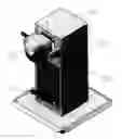
Drawing 1 is a front view of the base with inflated mechanism for vending machine of deflated balls.
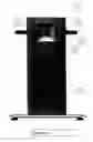
Drawing 2 illustrates a side view without case in perspective of the base with inflated mechanism for vending machine of deflated balls.
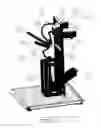
Drawing 3 is a superior side view in its left angle in perspective of the base with inflated mechanism for vending machine of deflated balls.
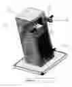
Drawing 4 is an isometric side view of the base with inflated mechanism for vending machine of deflated balls.
With reference to such drawings, the base with inflated mechanism for vending machine of deflated balls is comprised mainly with:
-
- A. Base with inflated mechanism for vending machine of deflated balls comprised with one pedal 1 located in the front exterior part of the case 2 of the vending machine, which is connected in the internal part of the same to two pneumatic pistons 3, which in their superior part are connected to an exit 4 which contains a manometer 5 and wherein a hose 6 is connected, joined to a connection 7 in T form which main function is to divide the flow of air to two parts. On one side this connection 7 in T form in its left side part front view joined to an elbow joint 8 and of which it joins a hose 9 that goes up to a hole 10 located in the mid superior part front view of the vending machine that contains a valve 11 to inflate the ball. This group of hoses and connections is retractable for its best use in the inflating of the ball, since in connection 7 of the T there is a pulley wheel 12 to which two of its extremes are connected, two springs 13 that allow its retractable function, which are anchored respectively to a metal ear welded located on the internal posterior vertex of the case 2 that forms in its inferior part to the vending machine. On the other side, from the connection, 7 T a hose exits 14 towards the right side front view and in a perpendicular manner to the hose of the inflated 9, that has in its final part a relief valve 15 and that it is located in the right handle front view 16 of the vending machine, which is covered by a lever 17 which main function is to release the excess air of the ball 18 that is injected by the valve 11 and to avoid in this manner that the ball breaks due to the excess of air.
The base with inflated mechanism for vending machine of deflated balls proposed by the invention has been conceived specifically to resolve this existing problem until today in the market since there was no vending machine that offered to the consumer public the sale of deflated balls that may be inflated as soon as extracted by these directly in the vending machine, opening in this manner a new system of commercialization of plastic inflated balls and a new vending machine for these that contain within their structure a pump to inflate the ball.
Claims
1. (canceled)
2. An apparatus as defined in claim 11 wherein the metal ears used for fixing or anchoring the springs can be substituted by hoops or eyebolts, and these can be located in any other internal point of the case.
3. An apparatus as defined in claim 11 wherein the hoses used can be substituted by any other type of hose or pipe.
4. An apparatus as defined in claim 11 wherein the elbow joint and the T used can be of any material, or in its case any or both may not be used depending on the type of connection of the pistons' pump.
5. An apparatus as defined, in claim 11 wherein the lever and its respective valve of relief used may be substituted by any other type of sensor, among which we could find the distance sensors, pressure sensors, proximity sensors and the volume sensors, among others; or they can be located in another angle or position of the base with inflated mechanism for vending machine.
6. An apparatus as defined in claim 11 wherein the number of pneumatic pistons used can be increased or decreased.
7. An apparatus as defined in claim 11 wherein the springs used can vary in their number and they can be substituted by any type of elastic bands or flexible tensors; or in its case eliminated totally within the mechanism and avoid in this manner that the inflated systems is retractable.
8. An apparatus as defined in claim 11 wherein the base with inflated mechanism instead of being located in the inferior part of the vending machine it may be located in any other position in regards to the vending machine.
9. An apparatus as defined in claim 11 wherein the pistons used to inflate the ball can be substituted by at least an electric or mechanic compressor, or at least any type of mechanic or electric bellows that provides air at pressure to inflate the ball.
10. An apparatus as defined in claim 11 wherein the pedal used can be substituted by at least one crank, or by at least one lever, or by at least any other activation moved in an electric or mechanic manner.
11. A ball inflating apparatus comprising:
a case;
a pedal accessible at a front exterior side of the case;
a pneumatic piston-cylinder assembly located inside the case and linked to the pedal to be actuated by the pedal;
an outlet hose extending from the piston-cylinder assembly;
a manometer on the outlet hose;
a T-connector on the outlet hose;
an elbow joint on the T-connector;
a ball inflating valve accessible at the front exterior side of the case;
an inflating hose extending from the elbow joint to the ball inflating valve;
a pulley wheel on the T-connector;
a pair of ears at an upper rear interior portion of the case;
a pair of springs connecting the pulley wheel to the cars;
a relief valve at the front exterior side of the case;
a relief hose extending from the I-connector to the relief valve; and
a lever covering the relief valve.
Images & Drawings included:

Sources:
- United States Patent and Trademark Office - verify current appl. status at the USPTO↗
Recent applications in this class:
- » 20250099818 2025-03-27
Smart Portable Golf Ball Dispenser - » 20240293703 2024-09-05
Golf Ball Dispenser With Embedded Display Device, Separate Front Waterfall Panel and/or Blower Assembly - » 20240216763 2024-07-04
EXTENDABLE BASEBALL CARRIER - » 20240082648 2024-03-14
Portable sports rack and delivery system - » 20240017131 2024-01-18
Ball Dispensing Mechanism for Arcade Games - » 20230053992 2023-02-23
BALL SPORTS TRAINING SYSTEM - » 20220212063 2022-07-07
Portable sports rack and delivery system - » 20220203178 2022-06-30
Golf Ball Dispenser With Embedded Display Device, Separate Front Waterfall Panel and/or Blower Assembly - » 20210275876 2021-09-09
Control system for regulation balls in a football field and regulation ball support for same - » 20210069555 2021-03-11
Doc holliday's basketball 6 shooter