Flood/wind resistant building
US20100183374A1
2010-07-22
12/657,354
2010-03-01
✅ Patent granted
US 8,066,451 B2
2011-11-29
-
-
Frederic L Lagman
2030-03-01
Abstract:
The proposed invention is the building design application of a foundation system that is flood and wind resistant. The foundation system consists of a building superstructure 1, foundation raft assembly 2, and steel pole anchor with bent steel plate guide assembly 3. The foundation raft assembly 2 typically bears on grade 4, but floats at water level 5 during a flood. The steel pole anchor with bent steel plate guide assembly 3 has a shaped bent steel plate that wraps around a steel pole anchor, and attaches to the foundation system corners.
Inventors:
- James J. Ewers 1 🇺🇸 Lake Wylie, SC, United States
- Francis P. Neumann 1 🇺🇸 Midland, NC, United States
Interested in similar patents?
Get notified when new applications in this technology area are published.
Classification:
E04H9/14 » CPC main
Buildings, or groups of buildings, or shelters adapted to withstand or provide protection against abnormal external influences, e.g. war-like action, earthquake, extreme climate against other dangerous influences, e.g. tornadoes, floods
Y02A50/00 » CPC further
in human health protection, e.g. against extreme weather
B63B35/44 IPC
Vessels or similar floating structures specially adapted for specific purposes and not otherwise provided for Floating buildings, stores, drilling platforms, or workshops, e.g. carrying water-oil separating devices
E02D31/04 IPC
Protective arrangements for foundations or foundation structures ; Ground foundation measures for protecting the soil or the subsoil water, e.g. preventing or counteracting oil pollution against ground humidity or ground water Watertight packings for use under hydraulic pressure
E02D27/52 IPC
Foundations as substructures; Foundations for special purposes Submerged foundations, i.e. submerged in open water
E02D27/32 IPC
Foundations as substructures Foundations for special purposes
Description
Provisional patent application No. 61/205,607 filed on Jan. 22, 2009.
No federally sponsored research/development provided.
Every year, extreme weather causes flood and wind damage to buildings located on land adjacent lakes, rivers, and seas. Regardless of this problem, buildings continue to be constructed and repaired on these lands. A solution of this problem would be the construction of flood and wind resistant buildings on these lands.
U. S. Patent No. 20040261338 discloses an arrangement of a buoyant foundation that typically bears on grade, and floats during a flood. This arrangement consists of an insulated floor deck, metal framework, molded plastic foam filled caissons, custom fabricated hollow metal guide masts, and a concrete slab on grade. It appears that the arrangement depends on the weight of the building to resist wind uplift forces. It also appears that this arrangement has not been commonly built because of its excessive cost above that of a traditional building foundation. The fabrication and erection cost of this arrangement need to be reduced for it to be commonly built.
The proposed invention uses a unique foundation system to resist flood and wind damage. This system consists of a foundation raft assembly that serves as a floor, insulation, and foundation. This foundation raft assembly typically bears on grade, and floats during a flood. It is anchored and guided by steel poles embedded in the ground at its corners. This invention provides for an uninterrupted use of the building utilities during a flood.
The proposed invention is graphically described by the following drawings:
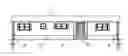
FIG. 1 a building elevation showing the foundation system bearing on grade.
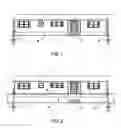
FIG. 2 a building elevation showing the foundation system floating during a flood.
FIG. 3 a foundation plan showing the foundation raft assembly, plumbing trenches, and steel pole anchors with bent steel plate guides.
FIG. 4 a section through a plumbing trench showing a special flotation billet with pipe support accessories.
FIG. 5 a wall section showing the foundation system bearing on grade.
FIG. 1 and FIG. 2 show a building superstructure 1 of a standard single floor prefabricated modular home. The proposed invention can also be used for a site built superstructure of similar shape and materials. The foundation raft assembly 2 typically bears on grade 4, that is graded, compacted, and treated with a termite chemical soil barrier. The foundation rail assembly 2 floats at water level 5 during a flood. Steel pole anchors with bent steel plate guides 3 are made from hollow steel pipe and structural steel plate. The sizes and capacities of these members will be determined by structural analysis of the flood and wind forces resisted by the foundation system. The stationary steps 6 will continue to bear on grade 4 during a flood.
FIG. 3 shows a plan view of the foundation raft assembly composed of attached flotation billets 7 that are made of extruded polystyrene rigid insulation with a minimum 55 PCF flotation capacity. The standard flotation billet size equals 32×32×96 inches. The flotation billets 7 are manufactured with a 2×6 wood top inset frame, and covered with a polyethylene film moisture barrier. Steel pole anchors with bent steel plate guides 3 are attached at the foundation system corners. Large plumbing trenches 8 and small plumbing trenches 9 are made in the foundation raft assembly as required by the building superstructure plumbing layout. A plumbing access space 10 is made with a removable panel at a side of the foundation raft assembly. Water and sewer piping are installed in the plumbing trenches. The sewer discharge piping connects to the utility service piping with a pressure release coupling at the plumbing access space 10. The main water supply piping connects to the utility water piping with a 12 feet length of coiled pressure rated hose at the plumbing access space 10. Electrical and telephone service is of the standard overhead type.
FIG. 4 shows a special flotation billet 12 manufactured with a plumbing trench that has a 2×6 wood top inset frame at the trench perimeter. Pipe hangers 13 attached to the top inset frame support plumbing pipes. The special flotation billets 12 are manufactured from standard flotation billets, and typically bear on grade 4. The plywood deck 11 above the trench will be cut into removable panels for plumbing access.
The wall section drawing FIG. 5 shows the building superstructure 1 fastened to a plywood deck 11 composed of ½ inch single floor grade plywood panels. The plywood deck 11 is fastened to the standard flotation billets 7 that typically bear on grade 4. FIG. 5 also shows in elevation, the steel pole anchor with bent steel plate guide 3. The bent steel plate guide has a “U” shape with elongated feet at the legs. This guide wraps around the steel pole anchor, and its feet attach to the building stud wall sill plate and flotation billet frame with wood fasteners. A high tensile steel removable bolt 15 inserts through the steel plate guide and steel pole anchor when the foundation system bears on grade 4. This anchorage resists both lateral and uplift wind forces. The steel pole anchor 3 embeds in a circular concrete footing 16. The size and depth of the concrete footing will be determined by structural analysis of the flood and wind forces resisted by the foundation system. Prior to a flood, the removable bolts 15 are removed, which permits the foundation system to rise with the floodwater. This anchorage permits vertical movement, but resists horizontal movement caused by flood forces. The steel pole anchor 3 is fabricated with a steel plate endcap 14 that prevents liftoff of the foundation system during a flood.
Claims
1. The proposed invention claims a unique design application for a flood and wind resistant building. This design application is a foundation system that can resist flood and wind damage. This foundation system applies to a foundation raft assembly 2 made with a plywood deck 11 fastened to flotation billets 7,12 that have sufficient buoyant capacity to float the building superstructure 1 during a flood. The foundation raft assembly 2 has plumbing trenches 8,9 made with flotation billets 12, and a plumbing access space 10 that permits continued use of the building utilities during a flood. This foundation system also applies to a steel pole anchor with bent steel plate guide assembly 3 that has a hollow steel pipe anchor embedded in a circular concrete footing 16, a shaped bent steel plate guide, steel plate endcap 14, and removable steel bolt 15. The proposed invention foundation system can be factory built by a modular home manufacturer, or site built by a licensed homebuilder. It is made with standard, light weight, low technology construction materials and products, which will make it comparable in cost to a traditional building foundation.
Images & Drawings included:


Sources:
- United States Patent and Trademark Office - verify current appl. status at the USPTO↗
Recent applications in this class:
- » 20250290342 2025-09-18
Fire Shelter and Method - » 20250207425 2025-06-26
REMOVEABLE ABOVE-GROUND STORM SHELTER AND METHOD OF USE - » 20240301714 2024-09-12
SHELTER APPARATUS AND METHOD THEREOF - » 20240301713 2024-09-12
Hurricane Asset Protection System for preparing real estate, vehicles, and other tangible property for natural and manmade calamities and their aftermath - » 20240247515 2024-07-25
Rafter Support Assembly and Method of Using Same - » 20240117651 2024-04-11
SECURITY VAULT - » 20230358067 2023-11-09
Security apparatus for protecting a surface - » 20230175280 2023-06-08
EMBER SCREEN - » 20230108669 2023-04-06
Structures and methods for lunar utilization - » 20220341206 2022-10-27
Bookshelf Saferoom