Modular component mattress
US20100192299A1
2010-08-05
12/322,415
2009-02-03
Abstract:
A modular component mattress can be easily assembled by customer with selectable and interchangeable main mattress components, such as air bladders, springs, water bladders, foam or heater is inserted into a pillow top/tight top etc cover, as well as foam rails that are inserted into a zipper fabric sleeve inside the perimeter of a mattress cover.
Interested in similar patents?
Get notified when new applications in this technology area are published.
Classification:
A47C21/048 » CPC main
Attachments for beds, e.g. sheet holders, bed-cover holders ; Ventilating, cooling or heating means in connection with bedsteads or mattresses; Devices for ventilating, cooling or heating for heating
A47C27/05 » CPC further
Spring, stuffed or fluid mattresses or cushions specially adapted for chairs, beds or sofas with spring inlays with padding material, e.g. foamed material, in top, bottom, or side layers
A47C27/053 » CPC further
Spring, stuffed or fluid mattresses or cushions specially adapted for chairs, beds or sofas with spring inlays with padding material, e.g. foamed material, in top, bottom, or side layers with only one layer of foamed material
A47C27/081 » CPC further
Spring, stuffed or fluid mattresses or cushions specially adapted for chairs, beds or sofas; Fluid mattresses or cushions of pneumatic type
A47C27/085 » CPC further
Spring, stuffed or fluid mattresses or cushions specially adapted for chairs, beds or sofas; Fluid mattresses or cushions of liquid type, e.g. filled with water or gel
A47C17/86 IPC
Sofas; Couches; Beds Parts or details for beds, sofas or couches only not fully covered in a single one of the sub-groups , , , , , or ; Drawers in or under beds
A47C21/04 IPC
Attachments for beds, e.g. sheet holders, bed-cover holders ; Ventilating, cooling or heating means in connection with bedsteads or mattresses Devices for ventilating, cooling or heating
A47C23/04 IPC
Spring mattresses with rigid frame or forming part of the bedstead, e.g. box springs; Divan bases; Slatted bed bases using springs in compression, e.g. coiled
Description
CROSS REFERENCE TO RELATED APPLICATIONS
- U.S. Pat. No. 2,326,441 Cunningham
- U.S. Pat. No. 5,953,779 Schwartz
- U.S. Pat. No. 5,701,623 May
- U.S. Pat. No. 5,537,699 Bonaddio
- U.S. Pat. No. 6,701,552 Suzuki
- U.S. Pat. No. 6,711,767 Klamm
- U.S. Pat. No. 6,546,576 Lin
- U.S. Pat. No. 6,006,524 Park
- U.S. Pat. No. 4,455,472 Moss
- U.S. Pat. No. 4,423,308 Callaway
BACKGROUND
1. Field of Invention
This invention relates to a modular component mattress can be easily assembled by customer with selectable and interchangeable main mattress components, such as air bladders, springs, water bladders, foam or heater is inserted into a pillow top/tight top etc cover, as well as foam rails that are inserted into a zipper fabric sleeve inside the perimeter of a mattress cover.
2. Description of Prior Art
Generally, mattresses are formed with a mattress central portion or core surrounded by a mattress border construction. The mattress central portion, or core, may comprise a series of coil springs connected together and encased in a quilted fabric. Alternatively, the mattress central portion may comprise polyurethane or latex foam layers or synthetic or natural fibers, optionally in combination with springs, and encased in quilted fabric. The central portion might also constitute an air mattress or water mattress or other body-supporting mattress structure.
The mattress has been retailed through retail stores where the mattress could be lied upon and felt for comfort at the point of sale. Surprisingly, people will buy mattresses without ever lying upon it through an online, internet or catalogue purchase. The air bed has made delivery by common courier possible due to it's compact size, however it's greatest feature is the adjustable firmness, so that a firmness satisfaction is guaranteed for the person but also their spouse can adjust the air pressure to obtain the firmness for their side of the mattress.
Mattress border constructions stabilize the edge or border portion of the mattress. It is desirable to have a more firm or more rigid border portion surrounding a less firm, body-supporting mattress central portion. Mattress border constructions of various types have been disclosed in the prior art. U.S. Pat. No. 5,537,699 discloses a mattress border construction formed with a foam rail sleeve surrounding a plurality of springs arranged in a row. The foam rail sleeve defines a core into which the row of springs is inserted. The foam is slit along its length so that it may be opened to permit insertion of the row of springs. The slit is then sealed with a liquid adhesive or a hot melt adhesive. The mattress border construction forms a periphery around the mattress center section, and is joined to the mattress center section also with a liquid adhesive or a hot melt adhesive. The adhesive coats the foam strands and penetrates into the foam pores to securely bond the mattress border construction to the mattress center section. It has been found, however, that the liquid adhesive can be difficult to apply, and can create more need for substantially clean up of applicators and surrounding surfaces on which excess adhesive collects. In addition, liquid adhesive and hot melt adhesive cannot be pre-applied before the mattress border construction is delivered to a mattress fabricator.
U.S. Pat. No. 5,701,623 shows a composite mattress topper, as opposed to a complete mattress construction. The topper has a latex foam rubber core section surround by border sections of urethane foam. The border sections are attached to the core section with adhesive to create the finished topper. The adhesive is not shown as able to be pre-applied before the component parts are shipped for later assembly.
A mattress assembly shown in U.S. Pat. No. 5,953,779 has a stack of foam mattress elements positioned one atop the other and joined together at their peripheral edges with hook and loop fasteners (VELCRO®). The fasteners keep the foam mattress elements aligned in stacked relation. The mattress so formed does not have a mattress border construction, and a retainer rope is secured around the outer edge of the mattress to hold the elements together. Additional holding support is provided by containment blocks optionally attached with VELCRO® to the head and foot of the mattress assembly.
U.S. Pat. No. 2,326,441 shows a mattress covering in which strips of fabric are secured to the sidewall of a foam sponge rubber mattress core with an adhesive. The fabric strips form an anchor onto which the mattress covering material may be stitched. No mattress border construction is provided around the sponge rubber mattress core.
Mattresses have historically been assembled in the manufacturing facility. With manufacturing moving overseas to countries such as China, there was a economic advantage to reduce the shipping volume, since the shipping containers would not be close to their maximum weight capacity. Compressing components such as spring assemblies, or complete spring mattresses made economic sense. A problem occurred with mattresses using foam rails, in that the foam rail that was glued to the inner mattress cover would not return to it's original shape and wrinkles would result.
Also mattresses are now air, coil springs, and memory foam core having a separate material in the perimeter for reasons of increased vertical perimeter support. In the case of coil springs, the foam perimeter gives the feel or sensation of a soft mattress edge or side when the mattress is compressed laterally when sat or leaned against. Traditionally, this feel has made by gluing the coils or rowed sleeve of coils to the foam rail. A fabric rail sleeve, as in this invention, was not possible to sew to the cover as it would leave a visible stitch mark on the surface and interfere with quilting patterns, so the fabric rail sleeve was sewn to the perimeter and the bottom mattress cover zipper. As an alternative embodiment, this invention has added an inner cover under the surface of the mattress cover. This gives the benefit of allowing the sleeve to be sewn to it without stitches into the outer cover, as well provides a more attractive or value added inner surface for the customer when he assembles the mattress.
The water bed has a benefit over other mattresses in that when you initially enter the water bed it is already warm. This invention also obtains this by adding a low powered heater under the air bladder or mattress core. This is a novel approach to use this water bed style of heater in an air bed would seem impossible because there is seems to be no mass (water) or way of conducting the heat through the mattress. As well, the control for water beds must be very precise to obtain a comfort temperature, requiring a temperature sensor in a remote location a distance from the heater placed under the water bed bladder. This water bed type of temperature control would not function as a on/off type of control due slow heat transfer of the air, the heater would form an overheated area causing damage to bladder or combustion, as is the case of an empty water bed bladder. By having a heater which has approximately ⅓ the power of a water bed and a simple control, the invention can achieve a warm air mattress upon entry and allow the room temperature to be reduced in the evening to save energy.
The prior art shows the general approach to heating a mattress is by heating and circulating warm air through the mattress by a blower fan. This is an expensive method and would require all or partial replacement with this custom engineered mattress. This is seen in art references of U.S. Pat. No. 6,701,552 Suzuki, U.S. Pat. No. 6,711,767 Klamm, U.S. Pat. No. 6,546,576 Lin and U.S. Pat. No. 6,006,524 Park who show this type of approach. The other type of design is to direct heating elements on the or within the mattress as shown by U.S. Pat. No. 4,455,472 Moss and U.S. Pat. No. 4,423,308 Callaway. This invention simplifies the solution in terms of product cost as well as reduces power consumption due to the direct application of heat and the insulated configuration of heater as compared to the prior art. The modular or component design allows this not only to be used with a air bladder, but also a spring core, since the heater can be placed inside the mattress under the core and then mattress zipped shut. The sealed mattress would not allow access to the lower portion of the mattress to make it easy for placement of such a heater. This feature makes it even less important to actually lay of the bed before buying it, thus a safer buy for someone living in a remote area where it would not be worth the long drive to purchase a mattress.
SUMMARY
In accordance with the present invention is a modular component mattress that can be easily assembled by customer with selectable and interchangeable main mattress components, such as air bladders, springs, water bladders, foam or heater is inserted into a pillow top/tight top etc cover, as well as foam rails that are inserted into a zipper fabric sleeve inside the perimeter of a mattress cover.
OBJECTS AND ADVANTAGES OF THE INVENTION
This novel approach has the following advantages in that it:
- 1. allows for manufacturer and customer for compact transport of mattress, even a king size mattress in a small vehicle in it's unassembled state. The mattress is assembled up-side down so the cover is laid upside down and the core placed on the bottom side of the top of the cover after the base of the cover is unzipped and folded out of the way. The foam rails are then inserted in the perimeter foam rail sleeves. A layer of foam maybe placed in the mattress cover if desired. The core is then placed on the cover or foam and between the foam rail assemblies. A typical prior art method has head and foot edge foam rails linked by a fabric web across the lower 2 adjoining inner edges of the rails, ie head and foot rails and similarly left and right rails. Customers have assembled this with the fabric webs located near the top surface of the mattress rather than the bottom surface. In this event the fabric web would not prevent the lower edges of the mattress cover from bulging, nor the rails and outer edge of the mattress from lifting up when someone lays on the main core. The sleeves prevent this assembly error from occurring since there is no fabric web.
- 2. eliminates the glue operation for securing foam rails which in turn prevents wrinkling, as well as incomplete recovery, when the rails are compressed for shipping. This is a problem since most adhesives take up to 2 weeks to fully cure and once a product it is on the assembly line it must be packaged as the last step of the production. To package mattresses with spring cores, the finished mattress are put in a plastic bag which then have the air evacuated resulting in compression of spring assembly (core) and rails into a flattened state, which is then rolled and placed in a box. Since the adhesive is not fully cured, it causes the folded or wrinkled side fabric which is glued to the rail or rail enclosure to adhere to itself resulting in inability to come back to its full height once removed from the plastic bag. It also reduces discoloration from glue seepage to the outside of the cover and prevents the cover rotating or twisting relative to the foam rails and/or contents of cover preventing outer line or edge to remain straight and along the corner of the mattress edge
- 3. narrower side foam rails of 2 inch width are possible, reducing the more expensive rail as compared to core cost
- 4. allows a dissatisfied customer to exchange spring with say foam or air cores without, or switching (thus preventing full destruction of product for hygienic considerations) if a satisfaction warranty is offered. The customer can eventually replace a damaged or worn out component of the mattress rather than the whole mattress.
- 5. has a centrally located zipper on inner height of sleeve avoids visible zipper on bottom of mattress or feeling the zipper under the mattress surface
- 6. core of mattress, made of say pocket coil assembly, can be inverted or flipped within the mattress without inverting the cover.
- 7. if the mattress is moved or carried on it's side or inverted, the foam rails cannot become dislodged and fall behind the air, spring or foam core
- 8. a sleeve is easier to assemble rather than securing with Velcro tabs or strips, between cover and foam rail, that require alignment before pressing together.
- 9. the sleeve can be secured or closed with zipper, buttons, hook and loop or any other fabric securing devices.
- 10. foam rails cannot shift headward or footward in mattresses on adjustable bases. The foam rails can also be cut and or beveled at the hinge point and placed in individual sleeves along the length of the mattress to reduce mattress rigidity.
- 11. once zipped in, the foam is covered and not visible when cover is opened, this is aesthetically appealing and shows well for demonstrations at the point of sale.
- 12. with the foam securely zipped in the sleeves and a non-stretch bottom, the sides will not bow out and will hold a flat straight shape.
- 13. zipping foam rails into their sleeves before installing the core insert allows the bottom zipper to be further in from the edge, hence no corner button or cover relief is required for pulling cover over the combined core and rail assembly as described in the prior art of advantage 1. Having the zipper located further inward from the perimeter also provides better fire resistance properties since the mattress cover offers much better fire resistance to that of the zipper and bottom mattress cover.
- 14. allows the mattress cover to be folded in a space efficient way over a mattress cover which has the foam rails attached.
- 15. bottom zipper can start and finish at center of head end, this provides a location for air core hoses and heater cord to feed through cover.
- 16. reduced inventories and warehouse space as several colors and fabric designs would be available and rail types and core types would be compatible with the different types of mattress cover.
- 17. when you initially enter the water bed it is already warm. This invention also solves this problem by adding a low powered heater under the air bladder. As well, the control for water beds must be very precise to obtain a comfort temperature, requiring an temperature sensor in a remote location a distance from the heater placed under the water bed bladder. This temperature control would not function as a on/off type of control due slow heat transfer of the air, the heater would form an overheated area causing damage to bladder or combustion, as is the case of an empty water bed bladder. By having a heater which has approximately ⅓ the power of a water bed and a simple control, the invention can achieve a warm air mattress upon entry and allow the room temperature to be reduced in the evening to save energy.
- 18. This invention simplifies the solution in terms of product cost as well as reduces power consumption due to the direct application of heat and the insulated configuration of heater as compared to the prior art.
- 19. the multi tap heater element provide a range of heat settings and eliminates expensive power controls that add cost and electrical noise.
- 20. the heater can also vary the heat for each side of the bed by allowing the user to adjust the heater position or contact area between the two sides of the bed. The amount of area under each bladder will determine the temperature of each side of a king or queen mattress which are usually two joined bladders. For adjoining spring cores, a barrier of say vinyl or fabric will prevent an unwanted heating effect on one side.
- 21. One size heater can be used for all sizes and types of beds due to the low watt density of the heater.
BRIEF DRAWING DESCRIPTION
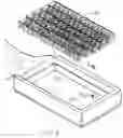
FIG. 1—shows an inverted mattress with the bottom mattress cover unzipped and folded open and spring core above.
FIG. 2—shows an inverted mattress with the bottom mattress cover unzipped and folded open and air core above.
FIG. 3—shows an alternate embodiment of a sectional rail sleeve
FIG. 4—shows an alternate embodiment using a hook and loop instead of zipper to secure the rail sleeve.
FIG. 5—shows section A-A of the mattress with foam rail in rail sleeve
FIG. 6—shows section A-A of the mattress with air rail in rail sleeve and hook and loop to close rail sleeve
FIG. 7—shows section A-A of a tight top mattress with spring rail in a spring enclosure to form the rail.
FIG. 8—shows the side view of an articulating foam rail for adjustable beds
FIG. 9—shows the mattress of FIG. 2 assembled with heater
FIG. 10—shows a king size inverted mattress open to receive two spring cores.
FIG. 11—shows an assembled king size inverted mattress with two spring cores, a heater, and boundary between the two sides of the bed
FIG. 12 shows the low power heater with heater wire connecting it to the heater control.
REFERENCE NUMERALS OF DRAWINGS
1. mattress cover
2. pillow top
3. lower fabric inner web
4. upper fabric inner web
5. inner cover
6. sleeve zipper
7. zipper grip
8. bottom mattress cover
9. bottom mattress cover zipper
10. spring core
11. air core
12. air hose
13. hook and loop closing strip
14. sectional fabric inner web
15. foam rail
16. edge cover
17. hook and loop fastener
18. air rail
19. tight top
20. spring enclosure
21. coil spring
22. valve or connection port
23. articulating foam rail
24. back section
25. buttocks section
26. thigh section
27. calve section
28. “V” cut
29. straight cut
30. sectional fabric inner web with hook and loop securing
31. pocket for coil spring
32. foam
33. heater
34. heater wire
35. flexible partition
36. heater control
37. heater element
38. heater circuit
39. selector switch
DETAILED DESCRIPTION OF DRAWINGS
FIG. 1—shows an inverted pillow top mattress cover 1 with the bottom mattress cover 8 unzipped and folded open to receive spring core 10 located over assembled mattress. The rails are shown zipped closed in the perimeter of the mattress cover.
FIG. 2—shows an inverted pillow top mattress cover 1 with the bottom mattress cover 8 unzipped and folded open to receive air core 11 located over assembled mattress. The rails are shown inside of the rail sleeve which is made from the edge cover 16, and the upper fabric web 4 and lower fabric web 3 which are secured closed by sleeve zipper 6 forming a closed sleeve in the perimeter of the mattress cover 1.
Air core 11 is then lowered into the mattress assembly and the air hose 12 would come out in the center of the 2 bottom mattress cover zippers 9 which secure the mattress bottom cover 8 when closed.
FIG. 3—shows an alternate embodiment of a rail sleeve which allows a rail to be inserted by pushing end of rail behind and then past center side sectional fabric inner web 14 into the corner. The rail is then bent and slid into opposite corner behind the opposite sectional fabric inner web 14. The head and foot rails are similarly inserted into one corner, bent and then inserted in opposite corner. Sectional fabric inner web with hook and loop closing 30, the same as the full length sleeves, can have some or all of them open and close,
FIG. 4—shows an alternative embodiment to FIG. 2 having a hook and loop securing instead of zipper. An inverted pillow top mattress cover 1 with the bottom mattress cover 8 unzipped and folded open to receive air core 11 located over assembled mattress. The rails are shown inside of the rail sleeve which is made from the edge cover 16, and the upper fabric web 4 and lower fabric web 3 which are secured closed by sleeve zipper 6 forming a closed sleeve in the perimeter of the mattress cover 1.
FIG. 5—shows section A-A of the mattress with a foam rail 15 in rail sleeve in pillow top mattress cover 1. The foam rail 15 is shown inside of the rail sleeve which is made from the edge cover 16, and the upper fabric web 4 and lower fabric web 3 which are secured closed by sleeve zipper 6 forming a closed sleeve in the perimeter of the mattress cover 1.
FIG. 6—shows section A-A of the mattress with an air rail 18 having a valve or connector port 22. The air rail can be inflated prior to or after insertion in sleeve. If the air rail is connected to the air pump then the rails could be inserted non-inflated at the factory. Since air rails do not need to be adjusted for varying firmness like the air core. It may be inflated by mouth and sealed and inserted in any type of core bed as well as replaced in the event of a leak.
The air rail 18 is shown inside of the rail sleeve which is made from the edge cover 16, and the upper fabric web 4 and lower fabric web 3 which are secured closed by a strip of hook and loop fastener 17 forming a closed sleeve in the perimeter of the mattress cover 1.
FIG. 7—shows section A-A of the mattress with a coil spring 21 in the sleeve with a tight top formed in the mattress cover 1. The coil spring 21 is place in pocket for coil spring 31 which are then place and secured side by side in a fabric sleeve spring enclosure 20 which forms the spring rail, and is placed in the rail sleeve. The rail sleeve which is made from the edge cover 16, part of the inner cover 5, and the upper fabric web 4 and lower fabric web 3 which are secured closed by sleeve zipper 6 forming a closed sleeve in the perimeter of the mattress cover 1.
The inner cover 5 is added to sew upper fabric inner web without causing visible stitching in the mattress cover 1. This inner cover 5 is not found in conventional mattresses with tight top 19. This inner cover 5 can also be used with pillow top mattresses
FIG. 8—shows the side view of an articulating foam rail 23 for adjustable beds. When back section 24 is elevated relative to buttocks section 25, the straight cut 29 will expand to allow flexibility in the mattress side. Similarly “V” cuts 28 allow elevation as well as downward flexing relative to their adjoining sections.
FIG. 9—shows the mattress of FIG. 2 assembled with heater having an inverted pillow top mattress cover 1 with the bottom mattress cover 8 unzipped and folded open and air core 11 located in assembled mattress. The rails are shown inside of the rail sleeve which is made from the edge cover 16, and the upper fabric web 4 and lower fabric web 3 which are secured closed by sleeve zipper 6 forming a closed sleeve in the perimeter of the mattress cover 1.
The heater 33 is place slightly headwardly directly in contact with the air bladder and the heater wire 34 and the air hose 12 would come out in the center of the 2 bottom mattress cover zippers 9 which secure the mattress bottom cover 8 when closed.
FIG. 10—shows a king size inverted pillow top mattress cover 1 with the bottom mattress cover 8 unzipped and folded open to receive two spring cores 10 located over assembled mattress. The rails are shown zipped closed in the perimeter of the mattress cover. A flexible partition 35 is located between the two spring cores 10 to create a heat boundary between the two spring cores of the bed to allow for individual temperature preference.
FIG. 11—shows a king size inverted pillow top mattress cover 1 with the bottom mattress cover 8 unzipped and folded with the two spring cores 10 located in the assembled mattress. The rails are shown zipped closed in the perimeter of the mattress cover. A flexible partition 35 is located between the two spring cores 10 to create a heat boundary between the two sides of the bed to allow for individual temperature preference. The heater 33 is located more to one side to provide higher temperature to that side of the bed. The heater wire 34 comes through the mattress cover at the meeting point of the two mattress zippers 9. The temperature setting is selected by temperature control 36. This configuration will be similar for all other types of mattress core whether it is pocket coil, foam, air bladder, water or air/water combination.
FIG. 12 shows the low power heater 33 with heater wire 34 connecting it to the heater control 36. The heater control 36 has a selector switch to select the desired heat setting. The heater has, in this preferred embodiment, 6 independent heater circuits 38 made of heater element 37. These are heater circuits are electrically configured in series or parallel or combination with each other by a selector switch that electrically powers some or all of the circuits. Managing the circuit connections eliminates the need for a variable power supply, however some high end models would have a variable power supply, as well independent heaters for each side of the bed. Although this heater is similar to a waterbed heater, in that it has a high temperature cut off switch, it has much lower watt density and overall power. However this heater remains with continuous power, with a means to reduce power by series circuits and/or phase shifting.
Operation
The mattress is inverted with pillow top 2 down and with the bottom mattress cover 8 unzipped and folded open to receive spring core 10 located over assembled mattress. The foam 32 is placed in cover if it is not already been placed at manufacture by quilting, adhesive or simple assembly. The rails, whether foam, air, or spring enclosure or any other type or combination of these, are placed and zipped closed in the perimeter of the mattress cover. The perimeter, which is made from the edge cover 16, part and the upper fabric web 4 and lower fabric web 3 is secured closed by sleeve zipper 6 forming a closed sleeve in the perimeter of the mattress cover 1.
An alternate embodiment of a rail sleeve, shown in FIG. 3, requires the rail to be inserted by pushing the end of rail behind and then past center side sectional fabric inner web 14 into the corner. The rail is then bent and slid into opposite corner behind the opposite sectional fabric inner web 14. The head and foot rails are similarly inserted into one corner, bent and then inserted in opposite corner. Sectional fabric inner web with hook and loop closing 30, the same as the full length sleeves, can be also used to reduce fabric and ease of assembly, as well have some or all of them open and close,
FIG. 6 shows section A-A of the mattress with an air rail 18 having a valve or connector port 22. The air rail can be inflated prior to or after insertion in sleeve. If the air rail is connected to the air pump permanently, then the rails could be inserted non-inflated at the factory and secured in the rail sleeve with air hose available for plugging into the pump. Since air rails do not need to be adjusted for varying firmness like the air core, it may be inflated by mouth and sealed and inserted in any type of core bed as well as replaced in the event of a leak.
FIG. 7—shows section A-A of the mattress with a coil spring 21 in the sleeve with a tight top formed in the mattress cover 1. The coil spring 21 is placed in pocket for coil spring 31 which are then place and secured by glue and/or sewing pockets side by side and the sewing them in the fabric sleeve type of spring enclosure 20 which forms the spring rail, which is then placed in the rail sleeve.
The upper fabric inner web 4 is preferably sewn to the outer upper edge of the mattress cover 1 where it meets the edge cover 16 for both pillow top and tight top mattresses, preventing visible stitching in the mattress cover 1. The lower fabric inner web 3 is preferably sewn with the zipper or can be sewn to the lower perimeter of edge cover 16.
The alternative embodiment inner cover 5 is added by sewing it as part of the quilted upper mattress cover or as a separate sheet. The upper fabric inner web is sewn to the inner cover 5 prior to the assembly with the cover operation. This inner cover 5 is not found in conventional mattresses with tight top 19.
The articulating foam rail 23 for adjustable beds must be placed in the rail sleeves with similar cuts directly opposite the width of the mattress so that one end of the mattress becomes the back section. When back section 24 is elevated relative to buttocks section 25, the straight cut 29 will expand to allow flexibility in the mattress side. Similarly “V” cuts 28 allow elevation as well as downward flexing relative to their adjoining sections.
The heater control 36 has a selector switch to select the desired heat setting. Managing the circuit connections eliminates the need for a variable power supply however some high end models would have a variable power supply, as well independent heaters for each side of the bed.
Conclusions Ramifications and Scope
Foam rails have been in waterbeds, airbeds and other types of mattress products for more than 20 years. Until this novel approach, manufacturers and consumers accepted the annoying and costly problems that are inherent with rails since they were manageable and no other design was offered. The novel approach not only overcomes and eliminates these problems, but also provides the following new advantages for mattresses:
It eliminates produces a glue operation which has a prolonged cure time problem causing wrinkling, as well as incomplete recovery, when the rails are compressed for shipping.
The additional cost for the rail sleeve and labor is more than compensated for by the cost reduction from narrower side foam rails and absence of rails allows the cover to be folded in a space efficient way to reduce shipping costs.
A modular component system provides reduced inventories and warehouse space while offering several colors and fabric designs would be available and rail types and core types would be compatible with the mattress cover.
A retailer can offer customer satisfaction as a dissatisfied customer could exchange say foam underlay, mattress core, or rails for a different type without the expense of replacing the entire mattress.
A mattress heater must be part of innovative mattress design for the future due to escalating energy costs in heating homes. When you initially enter the water bed it is already warm and will keep you warm even if the room temperature is significantly reduced. Many people have tried to design blower type systems to meet this need, but at significant initial cost. Noise and thermal/electrical inefficiency due to heat loss in a high air flow out of the mattress and fan/pump power losses, are also part this complex system. This invention simplifies the solution in terms of product cost as well as reduces power consumption due to the direct application of heat and the insulated configuration of the heater as compared to the prior art. The single heater can also vary the heat for each side of the bed by simply allowing the user to adjust the heater position or contact area between the two sides of the bed.
Thus the scope of the invention should be determined by the appended claims and their legal equivalents rather than the examples given.
Claims
I claim:1 A mattress comprising: a mattress cover, a core, and one or more rail, at least one fabric inner web, and an opening to insert said rail between said mattress cover and said fabric inner web, wherein a rail sleeve is formed from said fabric inner web sewn to said mattress cover to secure said rail to outer perimeter of said mattress cover and wherein said rail can be inserted between said mattress cover and said fabric inner web through said opening.
2. The said mattress of claim 1 further including a means for closing wherein said opening in said rail sleeve is secured in a closed configuration by said means for closing.
3. The said means for closing of claim 2 further including a zipper, button or hook and loop wherein said opening in said rail sleeve is closed by said zipper, said button and/or said hook and loop to secure said rail to outer perimeter of said mattress cover.
4. The said rail of claim 1 further including a rail made of foam, an inflatable vinyl air enclosure or spring rail assembly wherein said foam rail, said vinyl air rail, or said spring rail is secured by said means for closing in said rail sleeve.
5. The said fabric inner web of claim 1 further including a cover upper fabric and mattress cover side fabric of said mattress cover wherein said fabric inner web is sewn along the adjoining edge of said cover upper fabric and it's adjoining said cover side fabric of the said mattress cover.
6. The said mattress of claim 1 further including a cover base zipper wherein perimeter of said base zipper is located on or inward from lower inner longitudinal edge of said rail whereby fire safety is improved.
7. The mattress of claim 1 further including an inflatable air rail wherein said inflatable air rail is placed in said rail sleeve in the production factory and inflated by the user during assembly.
8. The mattress of claim 1 further including an inner cover wherein inner cover is sewn about upper perimeter of said mattress cover and said fabric inner web is sewn to said inner cover whereby stitching does not affect the outer said mattress cover appearance.
9. The foam rail of claim 4 further including a v-cut and straight cut in said foam rail at points of articulation wherein rigidity of said foam rail is reduced.
10. A component mattress system comprising; tight top, euro top and, pillow top mattress covers of varying colors, quilt pattern, firmness, and foam type; foam, spring, and air rails; foam, spring, and air cores of varying firmness and structure; foam sheets with varying material composition and firmness, wherein mattresses can be assembled at factory, warehouse, distributor, retail stores or customer homes from independent interchangeable components.
11. The said spring or said foam core of claim 10 further including at least one partition of said core and a means to secure between partitions wherein said partitions can be transported in a more compact shape for transportation than the assembled mattress.
12. A mattress comprising: a mattress cover, at least one air bladder and a heater wherein said heater is placed either in thermal contact with underside of said air bladder inside of said mattress cover or under said mattress cover.
13. The mattress of claim 12 further including a spring core wherein said spring core is used instead of said air bladder and said heater is placed under said spring core inside of said mattress cover and on top of bottom of said mattress cover, or under said mattress cover.
14. The heater of claim 12 further including a heater comprising more than one independent electrical circuits made from heater element and a switch wherein two or more circuits are electrically activated individually or activated connected in series or parallel with each other by means of said switch.
15. The mattress of claim 13 further including a flexible partition and a second spring core wherein said flexible partition is placed between first said spring core and second said spring core and wherein said heater is positioned between two said cores to adjust desired heat distribution to either side of said mattress.
16. The mattress of claim 12 further including a bottom mattress cover zipper wherein access opening is made for the placement, positional adjustment and removal of said heater.
Images & Drawings included:


Sources:
- United States Patent and Trademark Office - verify current appl. status at the USPTO↗
Similar patent applications:
Recent applications in this class:
- » 20250160529 2025-05-22
BED AIRFLOW AND TEMPERATURE CONTROL - » 20250151918 2025-05-15
BED AIRFLOW AND TEMPERATURE CONTROL - » 20250113922 2025-04-10
HEAT EXCHANGER BEDS AND RELATED SYSTEMS AND METHODS - » 20250057325 2025-02-20
A TEMPERATURE REGULATING FOAM PADDING WITH PASSIVE COOLING AND ACTIVE HEATING - » 20240251956 2024-08-01
VIBRATING BED - » 20240138579 2024-05-02
BED WITH FOOT WARMING SYSTEM - » 20240090678 2024-03-21
CONTROLLING A MATTRESS CLIMATE-CONTROL SYSTEM BASED ON THERMAL EVENT - » 20240008654 2024-01-11
Sleeping and resting apparatus - » 20230404279 2023-12-21
Bed microclimate control with preparation cycle - » 20230404278 2023-12-21
Bed Microclimate Control