Pyrolysis reactor
US20100196227A1
2010-08-05
12/669,727
2008-07-19
✅ Patent granted
US 8,585,868 B2
2013-11-19
WO; PCT/NL2008/050498; 20080719
WO; WO2009/014436; 20090129
Jill Warden | Joye L Woodard
The Webb Law Firm
2029-08-04
Abstract:
A device for pyrolysing biomass comprises: a reactor space; a first feed for biomass material connecting to the upper zone thereof; a second feed for heated heat carrier material connecting to the upper side of the reactor space; a first discharge for pyrolysis gas connecting to the upper zone of the reactor space at a distance from the first feed; and a second discharge for solid material, for instance carbon and heat carrier material, connecting to the underside of the reactor space. A substantial separation between the discharge flows of pyrolysis gas and solid material takes place predominantly under the influence of gravitational force, without interposing of a cyclone. The reactor space is modeled such that the direct flow from the first feed and the second feed to the first discharge is blocked. A mechanical mixer is present in the reactor space for the purpose of mixing the flow of biomass material with the flow of preheated heat carrier material.
Inventors:
- Robertus Hendrikus Venderbosch 4 🇳🇱 Enschede, Netherlands
- Lambertus Van De Beld 2 🇳🇱 Balkbrug, Netherlands
- Daan Assink 1 🇳🇱 Enschede, Netherlands
- Elwin Gansekoele 3 🇳🇱 Enschede, Netherlands
Assignee:
- BTG BIOLIQUIDS B.V. 1 🇳🇱 Enschede, Netherlands
Applicant:
Interested in similar patents?
Get notified when new applications in this technology area are published.
Classification:
C10B49/16 » CPC main
Destructive distillation of solid carbonaceous materials by direct heating with heat-carrying agents including the partial combustion of the solid material to be treated with moving solid heat-carriers in divided form
B01J8/003 » CPC further
Chemical or physical processes in general, conducted in the presence of fluids and solid particles; Apparatus for such processes; Feeding of the particles in the reactor; Evacuation of the particles out of the reactor in a downward flow
B01J8/005 » CPC further
Chemical or physical processes in general, conducted in the presence of fluids and solid particles; Apparatus for such processes Separating solid material from the gas/liquid stream
B01J8/008 » CPC further
Chemical or physical processes in general, conducted in the presence of fluids and solid particles; Apparatus for such processes Details of the reactor or of the particulate material; Processes to increase or to retard the rate of reaction
B01J8/087 » CPC further
Chemical or physical processes in general, conducted in the presence of fluids and solid particles; Apparatus for such processes with moving particles Heating or cooling the reactor
B01J8/10 » CPC further
Chemical or physical processes in general, conducted in the presence of fluids and solid particles; Apparatus for such processes with moving particles moved by stirrers or by rotary drums or rotary receptacles or endless belts
C10B53/02 » CPC further
Destructive distillation, specially adapted for particular solid raw materials or solid raw materials in special form of cellulose-containing material
B01J2208/0038 » CPC further
Processes carried out in the presence of solid particles; Reactors therefor; Controlling the process; Controlling the temperature by direct heat exchange adding a temperature modifying medium to the reactants Solids
B01J2208/0084 » CPC further
Processes carried out in the presence of solid particles; Reactors therefor; Details of the reactor or of the particulate material; Mixing elements; Stationary elements inside the bed, e.g. baffles
B01J2208/00867 » CPC further
Processes carried out in the presence of solid particles; Reactors therefor; Details of the reactor or of the particulate material; Mixing elements; Moving elements inside the bed, e.g. rotary mixer
Y02E50/10 » CPC further
Technologies for the production of fuel of non-fossil origin Biofuels, e.g. bio-diesel
Y02E50/10 » CPC further
Technologies for the production of fuel of non-fossil origin Biofuels, e.g. bio-diesel
Y02P20/145 » CPC further
Technologies relating to chemical industry; Feedstock the feedstock being materials of biological origin
Y02P20/145 » CPC further
Technologies relating to chemical industry; Feedstock the feedstock being materials of biological origin
B01J19/18 IPC
Chemical, physical or physico-chemical processes in general; Their relevant apparatus Stationary reactors having moving elements inside
C10B1/04 IPC
Retorts; Stationary retorts Vertical retorts
C10B49/08 IPC
Destructive distillation of solid carbonaceous materials by direct heating with heat-carrying agents including the partial combustion of the solid material to be treated with hot gases or vapours, e.g. hot gases obtained by partial combustion of the charge while moving the solid material to be treated in dispersed form
Description
The invention relates to a device for subjecting biomass to pyrolysis, which device comprises:
a reactor with a housing and a reactor space present therein;
a first feed for biomass material or other organic material connecting to the upper zone of this reactor space;
a second feed for heated heat carrier material, for instance sand, connecting to the upper side of this reactor space;
a first discharge for pyrolysis gas connecting to the upper zone of this reactor space at a distance from the first feed; and
a second discharge for solid material, for instance carbon and heat carrier material, connecting to the underside of this reactor space.
Such a reactor is known in many embodiments from, among others, WO-A-03/106590, WO-A-2007/017005 and DE-A-197 38 106.
Pyrolysis gas already occurs in the reactor space in the region of the mixer. This gas entrains fine carbon particles. The undesirable phenomenon may hereby occur that these fine particles accumulate in a separating cyclone forming part of the device, and cause blockage thereof after a period of time.
It is an object of the invention to solve this problem.
In this respect the invention provides a device of the above described type which has the feature that the reactor space is modelled such that the direct flow from the first feed and the second feed to the first discharge is blocked;
a mechanical mixer is present in the reactor space for the purpose of mixing the incoming flow of biomass material with the incoming flow of preheated heat carrier material; and
the maximum average velocity of the gas and the thereby entrained material in the reactor space downstream of the mixer at a temperature in the range of about 400° C.-550° C. is about as great as the terminal falling velocity, such that at least a substantial separation between the discharge flows of respectively pyrolysis gas and solid material takes place predominantly, and in any case for more than 50%, under the influence of gravitational force, in particular without interposing of a cyclone.
These measures according to the invention can effectively prevent any clogging and blocking occurring, despite the carbon and other solid material being of a somewhat tacky nature.
The structure according to the invention is able to wholly prevent the described undesirable phenomenon of the prior art. Carbon and, depending on the composition of the biomass, sometimes non-converted fibres and heat carrier material is discharged according to the invention substantially only via the second discharge, and the first discharge discharges substantially only pyrolysis gas.
Other than in the prior art, a direct flow, to be considered a short-cut flow, from the first feed and the second feed to the first discharge is effectively prevented according to the invention.
According to the invention substantially all solid particles are separated from the pyrolysis gas in the first part of the reactor where the mechanical mixer is situated.
The described separation can be effected in diverse ways. The reactor can for instance consist of two sub-spaces, i.e. the actual reactor space in which the mixer is situated, and a discharge part which connects on the underside to the lower part of said first sub-space and which connects on the upper side to the first discharge.
The velocity can for instance be set such that v<10 m/s, preferably v<5 m/s, more preferably v<2 m/s, and for a practically complete separation v<1 m/s.
In another embodiment the device has the special feature that an at least more or less vertical baffle is situated in the reactor space which connects to the upper wall of the reactor space, whereby the flow from the mixer, comprising a mixture of pyrolysis gas and solid material, and/or the part-flows of pyrolysis gas and solid material can only reach respectively the first discharge and the second discharge by passing over the lower edge of the baffle.
The reactor is preferably embodied such that the lower zone of the reactor space has a form narrowing toward the second discharge.
The invention will now be elucidated on the basis of the accompanying drawings.
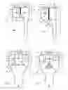
In the drawings the FIGS. 1, 2, 3 and 4 show four respective random exemplary embodiments of the pyrolysis reactor according to the invention.
Functionally corresponding components are designated in all the figures with the same reference numerals. The design and relation to other components may differ in the different embodiments.
FIG. 1 shows a device 1 for subjecting a flow of biomass material or other organic material 5 to pyrolysis. The device comprises a reactor 6 with a housing 7 and a reactor space 8 present therein, a first feed 10 for a flow of biomass material 5 connecting to the upper zone 9 of this reactor space 8, a second feed 11 for preheated heat carrier material 12 connecting to the upper part 9 of this reactor space 8, a discharge 13 for pyrolysis gas 14 connecting to upper zone 9 of reactor space 8, this discharge 13 being in the shown manner a substantial distance from first and second feeds 10, 11, in addition to a second discharge 16 for a flow of solid material 17, such as carbon, possibly remaining fibres and heat carrier material, connecting to lower zone 15 of reactor space 8.
The separation between the discharge flows of pyrolysis gas 14 and solid material 17 takes place substantially only under the influence of gravitational force, since the average velocity of the gas and the solid material entrained thereby has a low value, for instance 5 m/s, downstream of mixer 18. By way of comparison: a cyclone generates flow speeds in the order of 20 m/s and more. Otherwise than a known pyrolysis reactor, device 1 does not comprise a cyclone.
Reactor space 8 is modelled such that the direct flow from first feed 10 and second feed 11 to first discharge 13 is blocked, so that no “short-cut flow” can occur. The flows 14 and 17 in reactor space 8 are indicated with arrows. It will be apparent that these arrows serve only by way of orientation, and that the actual flows have a more complex character.
Present in reactor space 8 is a mechanical mixer 18, the schematically drawn blades of which are driven rotatingly by a motor (not shown). The mixer serves to mix the flow of biomass material 5 with heated heat carrier material 12 such as sand.
Situated in reactor space 8 is a vertical baffle 19 which connects against upper wall 20 of reactor space 8.
The lower zone 15 of reactor space 8 has a form narrowing toward second discharge 16. Side walls 21, 22 of this narrowing part have an angle to the vertical of less than 30°.
FIG. 2 shows a reactor 2 with a construction differing from that of FIG. 1 in the sense that baffle 19 has a greater vertical dimension but is still roughly the same distance from wall 23 located thereunder (this wall 23 having an inclining position in this embodiment) as from the horizontally placed wall 23 in the embodiment of FIG. 1.
FIG. 3 shows a device 3 in which a central peripheral baffle 19 connects to upper wall 20. Situated on the underside of mixer space 24 is a horizontal deflecting battle 25 which deflects flows 14, 17 laterally in the shown manner such that the flow of pyrolysis gas 14 undergoes a certain change in direction and can thus be more easily discharged to the two first discharges 13.
FIG. 4 shows a reactor 4 which differs from reactor 3 of FIG. 3 in the sense that the horizontal deflecting battle 25 is replaced by a roughly cone-shaped deflecting body 26 which makes it easy for the flow of solid material 17 to be guided downward in the direction of second discharge 16.
Claims
1-7. (canceled)
8. A device for subjecting biomass to pyrolysis, which device comprises:
a reactor with a housing and a reactor space present therein;
a first feed for biomass material or other organic material connecting to the upper zone of this reactor space;
a second feed for heated heat carrier material, for instance sand, connecting to the upper side of this reactor space;
a first discharge for pyrolysis gas connecting to the upper zone of this reactor space at a distance from the first feed; and
a second discharge for solid material, for instance carbon and heat carrier material, connecting to the underside of this reactor space;
wherein the reactor space is modeled such that the direct flow from the first feed and the second feed to the first discharge is blocked;
wherein a mechanical mixer is present in the reactor space for the purpose of mixing the incoming flow of biomass material with the incoming flow of preheated heat carrier material; and
wherein the maximum average velocity (v) of the gas and the thereby entrained material in the reactor space downstream of the mixer at a temperature in the range of about 400° C.-550° C. is about as great as the terminal falling velocity, such that at least a substantial separation between the discharge flows of respectively pyrolysis gas and solid material takes place predominantly under the influence of gravitational force, in particular without interposing of a cyclone.
9. The device as claimed in claim 8, wherein v<10 m/s.
10. The device as claimed in claim 8, wherein v<5 m/s.
11. The device as claimed in claim 8, wherein v<2 m/s.
12. The device as claimed in claim 8, wherein v<1 m/s.
13. The device as claimed in claim 8, wherein an at least more or less vertical baffle is situated in the reactor space which connect to the upper wall of the reactor space, whereby the flow from the mixer, comprising a mixture of pyrolysis gas and solid material, and/or the part-flows of pyrolysis gas and solid material can only reach respectively the first discharge and the second discharge by passing over the lower edge of the baffle.
14. The device as claimed in claim 8, wherein the lower zone of the reactor space has a form narrowing toward the second discharge.
15. The device as claimed in claim 13, wherein the lower zone of the reactor space has a form narrowing toward the second discharge.
Images & Drawings included:

Sources:
- United States Patent and Trademark Office - verify current appl. status at the USPTO↗
Similar patent applications:
- » 20240301291
CONTINUOUS-FLOW PYROLYSIS REACTOR, POSITIVE-PRESSURE FEED HOPPER FOR PYROLYSIS REACTOR, KILN FOR PYROLYSIS REACTOR, AND PYROLYSIS SYSTEM - » 20250188373
PYROLYSIS REACTOR, PYROLYSIS SYSTEM AND METHODS OF USE THEREOF - » 20250188374
PYROLYSIS REACTOR, PYROLYSIS SYSTEM AND METHODS OF USE THEREOF - » 14488337
Biomass pyrolysis reactor with integrated quench and method for converting biomass to liquid bio-oil - » 20080099325
Microwave induced pyrolysis reactor and method - » 20090008292
Pyrolysis reactor conversion of hydrocarbon feedstocks into higher value hydrocarbons - » 10313424
Method of on-line coating of a film on the inner walls of the reaction tubes in a hydrocarbon pyrolysis reactor - » 20090250377
Advanced materials for regenerative pyrolysis reactors, methods, and reactors using the same - » 11355794
Method and apparatus to obtain high pressures for a continuous-flow pyrolysis reactor - » 20090026421
OPTIMIZED LASER PYROLYSIS REACTOR AND METHODS THEREFOR
Recent applications in this class:
- » 20240352319 2024-10-24
FAST PYROLYSIS HEAT EXCHANGER SYSTEM AND METHOD - » 20220372373 2022-11-24
Combined hydrothermal liquefaction and catalytic hydrothermal gasification system and process for conversion of biomass feedstocks - » 20190071606 2019-03-07
Combined hydrothermal liquefaction and catalytic hydrothermal gasification system and process for conversion of biomass feedstocks - » 20180346817 2018-12-06
Pyrolysis reactor with optimized reaction sequencing - » 20180023003 2018-01-25
Combined hydrothermal liquefaction and catalytic hydrothermal gasification system and process for conversion of biomass feedstocks - » 20130331623 2013-12-12
Combined hydrothermal liquefaction and catalytic hydrothermal gasification system and process for conversion of biomass feedstocks - » 20120097517 2012-04-26
Method for pyrogasification of organic waste - » 20100163395 2010-07-01
Method for the rapid pyrolysis of lignocellulose - » 20050167259 2005-08-04
Method for the pyrolysis of a pyrolysable mass