Sea waves energy converter
US20100201130A1
2010-08-12
12/451,216
2007-04-29
✅ Patent granted
US 8,350,401 B2
2013-01-08
WO; PCT/EG2007/000014; 20070429
WO; WO2008/131786; 20081106
Javaid Nasri
2028-09-23
Abstract:
The conversion of wave energy in electrical or mechanical power is disclosed by means of the present subject-matter. When the sea wave is pushing up the floating cylinder (1) the transporter arm (2) is retracted in the sealed box (3), which converts the linear motion of transporter arm (2) by means of a chain belt (11) and a sprocket (8) m a rotational motion, when down the potential energy in the moving parts pull the transporter arm (2) which converts the linear motion into rotational motion by means of chain belt (11) and sprocket (7) in the same direction.
Interested in similar patents?
Get notified when new applications in this technology area are published.
Classification:
F03B13/1865 » CPC main
Adaptations of machines or engines for special use; Combinations of machines or engines with driving or driven apparatus ; Power stations or aggregates characterised by using wave or tide energy using wave energy using the relative movement between a wave-operated member, and another member, where the other member, i.e. rem is fixed, at least at one point, with respect to the sea bed or shore and the wom slides relative to the rem where the connection between wom and conversion system takes tension only
B63H19/02 » CPC further
Marine propulsion not otherwise provided for by using energy derived from movement of ambient water, e.g. from rolling or pitching of vessels
B63J3/04 » CPC further
Driving of auxiliaries from power plant other than propulsion power plant
F05B2260/4031 » CPC further
Function; Transmission of power through the shape of the drive components as in toothed gearing
F05B2260/505 » CPC further
Function; Kinematic linkage, i.e. transmission of position using chains and sprockets; using toothed belts
Y02E10/30 » CPC further
Energy generation through renewable energy sources Energy from the sea, e.g. using wave energy or salinity gradient
Y02E10/30 » CPC further
Energy generation through renewable energy sources Energy from the sea, e.g. using wave energy or salinity gradient
Y02T70/5236 » CPC further
Maritime or waterways transport; Measures to reduce greenhouse gas emissions related to the propulsion system; Less carbon-intensive fuels, e.g. natural gas, biofuels Renewable or hybrid-electric solutions
Y02T70/5236 » CPC further
Maritime or waterways transport; Measures to reduce greenhouse gas emissions related to the propulsion system; Less carbon-intensive fuels, e.g. natural gas, biofuels Renewable or hybrid-electric solutions
F03B13/18 IPC
Adaptations of machines or engines for special use; Combinations of machines or engines with driving or driven apparatus ; Power stations or aggregates characterised by using wave or tide energy using wave energy using the relative movement between a wave-operated member, and another member, where the other member, i.e. rem is fixed, at least at one point, with respect to the sea bed or shore
F03B13/10 IPC
Adaptations of machines or engines for special use; Combinations of machines or engines with driving or driven apparatus ; Power stations or aggregates Submerged units incorporating electric generators or motors
F03B13/12 IPC
Adaptations of machines or engines for special use; Combinations of machines or engines with driving or driven apparatus ; Power stations or aggregates characterised by using wave or tide energy
H02P9/04 IPC
Arrangements for controlling electric generators for the purpose of obtaining a desired output Control effected upon non-electric prime mover and dependent upon electric output value of the generator
Description
TECHNICAL FIELD
-
- Producing electricity from sea waves
- Design new Boats working without fuel
- Emergency generator for sea vessels
BACKGROUND ART
-
- Water Turbine based on difference in head
- High and low tide
- Underwater buoyant device
- Overtopping device (water turbine base)
- Oscillating water column
- Floating device (two floating device hinged together)
DISCLOSURE OF THE INVENTION
It is a mechanical device consists of
-
- 1—Floating cylinder
- 2—Transporter Arm
- 3—Sealed Converter Box
- 4—External cylindrical wire mesh
Its function based on two phenomena:
-
- Gravity
- Buoyant force (Archimedes)
It works like the motion of the Internal Combustion Engine but.
-
- 1—with active up and down stroke
- 2—with a very flexible stroke length (synchronized with the wave amplitude)
When the sea wave is up it push the Floating cylinder—1—(buoyant force) See drawing no. 1/11 whish push the Transporter arm—2—throw inside the Sealed Converter Box—3—which convert this linear motion into rotational motion clockwise, when the wave come down the weight of the movable mechanical parts and the arm—2—moves down by the Gravity Force inside the box—3—converting this motion into rotational motion in the same direction clockwise, then the rotational motion transport throw the rod—12—to the small flywheel—13—, the external wire mesh—4—saves the Floating cylinder—1—in a position under the arm—2—because of the free connection between them. (See drawing no. 1/11 and 5/11)
If we consider one converter as one cylinder (in an Internal Combustion Engine) so we can pout any number of converters in one station accumulated together electrically or mechanically to get the power we need. (See drawing no 8/11, 9/11)
Not: The movable mechanical parts is—2—, —10—(sea drawing no. 3/11) and the extra weight—23—if needed (see drawing no. 5/11)
Sealed Converter Box:
It consists of the following parts (NOT the serial numbers as the drawing no. 2/11, 3/11)
-
- 5—Driven ratchet gear
- 6—Negative ratchet gear (just for holding chain belt—11—in a vertical position and rotate negatively in clockwise direction
- 7—Tension ratchet gear (it is locked in clockwise direction) in down stroke and negative (rotate free in anticlockwise direction) in up stroke(or ratchet lever loaded in down stroke and unloaded in up stroke see drawing no. 6 part—77—as alternative solution)
- 8—Tension ratchet gear (it is locked in clockwise direction) in up stroke and negative (rotate free in anticlockwise direction) in down stroke (or ratchet lever loaded in up stroke and unloaded in down stroke see drawing no. 6/11 part—88—as alternative solution)
- 9—Metal wheel to guide the chain belt—11—in a fit position with the two gears—7—, —8—
- 10—Holder to hold —7—, —8—, —9—attached together to insure them working together and it is fixed with the transporter arm—2—11—Chain belt whish transmit the linear motion from the holder—11—to the gear—5—, —6—
How it Works:
- In the off condition (sea drawing no. 9/11) before starting the station which consists of more than one converter the Transporter Arm—2—is locked in the upper position (dead point) which makes the floating cylinder—1—moves up and down freely inside the cylindrical wiremesh—4—(unloading condition)
- By using an external starting motor to start up the station just to come over the inertia of the flywheel—18—so we have the following condition.
- Gears—5—, —6—rotate in clockwise direction, gears—7—, —8—rotate anticlockwise direction freely (negative motion), wheel—9—rotate in clockwise direction guiding the chain belt—11—moving safety inside the gears—5—, —6—, the holder—10—and the transporter arm—2—(fixed together) stay in its position without moving (dead point position)
Because the transporter arm fixed in that position far away from the floating cylinder.
-
- 3—When we release the transporter arm—2— it will take the position according to the level of the floating cylinder—1—and it will move up and down (synchronized with the wave amplitude)
Working Condition:
When the sea wave is coming up it will push the floating cylinder—1—then the transporter arm—2—and the holder—10—upward so gear—8—in a lock condition (not rotate in clockwise direction) so it results the tension T1 (see drawing no. 2/11) which enforce gear—5—to rotate in clockwise direction so the rod—12—and flywheel—13—which deliver the motion to the rod—17—(see drawing no. 9/11) and finally to the flywheel—18—then to the generator while gear—7—rotate anticlockwise When the sea wave is coming down it will pull the transporter arm—2—and the holder—10—downward so gear—7—in a lock condition (not rotate in clockwise direction) so it result the tension T2 (see drawing no. 2/11) which enforce gear—5—to rotate in clockwise direction then the rod—12—and flywheel—13—which deliver the motion to the rod—17—(see drawing no. 9/11) and finally to the flywheel—18—then to the generator while gear—8—rotate anticlockwise.
So any movement of the sea wave with any amplitude up and down it result a rotational motion in one direction
Not: if we consider the energy needed from one converter is E1 and the gravity energy whish results from the moving parts during downward is E2 and the energy results from the buoyant force is E3.
So E2 must be>E1. And E3 must be >(E1+E2).
By accumulating numbers of converters together we can decrees E2 (the weight of the moving parts) to a certain limit.
Alternative Holder:
We can replace holder—10—by another one as drawing no. 6/11 which indicate to the ratchet levers system
Increasing No. of Holder:
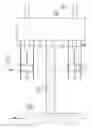
According to design parameters we can increase the numbers of holders as drawing no. 4/11.
Drawing no. 5/11 indicate to the free connection between floating cylinder—1—and the transporter—2—because of the erection purposes, (on and off conditions), maintenance, mechanical vibration and others.
Erection Locations:
-
- Near to the beach (see drawing no. 8/11, 9/11) —19—indicate to the sea wave
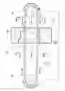
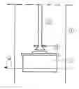
- On the beach (see drawing no. 10/11) in which—20— indicate to the beach mountain, —19—indicate to the sea wave, —15—is the concrete skeleton, —16—is a station room and —21—is a beach rocks
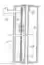
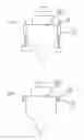
- On sea vessels (see drawing no. 11/11) —22—indicate to the sea vessel (FIG. 1 is on condition and FIG. 2 is an off condition)
BRIEF DESCRIPTION OF DRAWING
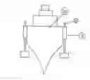
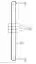
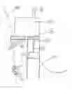
Drawing no. 1/11 represent to the main items of the converter which is:
1—Floating cylinder
2—Transporter arm moves up and down inside sealed box—3—
3—Sealed converter box
4—External wire mesh
12—Driven ax
13—Flywheel
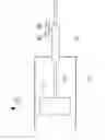
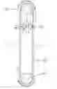
Drawing no. 2/11 represent to the main items of the sealed converter box which is:
- —5—, —6—, —7—, —8—are ratchet gears, —9—metal wheel—10—is a holder to fix—7—, —8—, —9—together at a precise distance from each others, —11—is a chain belt,
Drawing no. 3/11 represent to the fixation of the holder—10—with the transporter arm—2—
Drawing no. 4/11 represent to the increasing numbers of the holder —10—according to the design parameters
Drawing no. 5/11 represent to the free connection between the transporter arm—2—and the floating cylinder—1—inside the cylindrical wire mesh and the extra weight—23—
Drawing no. 6/11 represent to the alternative holder using ratchet levers instead of ratchet gears
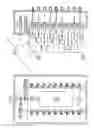
Drawing no. 7/11 represent to the skeleton of the station—15—with a foundation on the sea bed and the station room at a certain height above the sea level
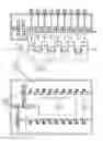
Drawing no. 8/11 represent to the station room—16—which include 18 converters and indicate floating cylinders at different heights according to the sea wav—19—
Drawing no. 9/11 represent to the station room—16—in off position and different wave amplitude—19—
Drawing no. 10/11 represent to the station room—16—erected direct on beach
Drawing no. 11/11 represent to the converters erected on sea vessel (FIG. 1 is an ON position, FIG. 2 is an OFF position)
Claims
1- Using chain belt or wire belt, transporter arm, floating cylinder and ratchet gears or ratchet leavers to convert the sea wave energy to mechanical or electrical energy (converter) under the influence of gravity force and buoyant force
2- Using unlimited numbers of converters in one station to produce electrical energy
3- Erect more thane one converter on sea vessels (as an emergency generator)
4- Design new boats in which its propeller depend direct on the mechanical motion resulted from the converter
Images & Drawings included:
Sources:
- United States Patent and Trademark Office - verify current appl. status at the USPTO↗
Similar patent applications:
- » 20200204040
Sea wave energy converter system to generate electricity using pioneer devices lined-up in particular arrangement - » 20090278356
Sea wave energy converter - » 20190063395
Sea wave energy converter capable of resonant operation - » 20130113214
Floating vessel that converts wave energy at sea into electrical energy - » 20190195188
Wave energy converter deep sea mounting system - » 17866083
Self-tuning wave energy converter (WEC) controller for changing sea states - » 20180335009
System for conversion of the whole kinetic energy of sea wave into electricity by one-way direct drive shaft converter, (ODSC system)
Recent applications in this class:
- » 20250043764 2025-02-06
FLOAT APPARATUS FOR HARNESSING WAVE ENERGY - » 20230323850 2023-10-12
BUOY, WAVE ENERGY CONVERTER COMPRISING SUCH BUOY AND METHOD OF MANUFACTURING A BUOY - » 20230213016 2023-07-06
Array for arranging wave energy converters in a wave power park - » 20220090574 2022-03-24
Hydro-wave power energy harnessing device and method of operation thereof - » 20210372361 2021-12-02
Assembly for transferring wave energy to an energy converter - » 20210010451 2021-01-14
WAVE FORCE GENERATION SYSTEM AND CONTROLLING METHOD THEREFOR - » 20200400116 2020-12-24
Wave power generation system and method for controlling same - » 20200224633 2020-07-16
Wave Powered Generator - » 20120240569 2012-09-27
Device to capture wave energy - » 20110304145 2011-12-15
Methods and devices for converting wave energy into rotational energy