Method of fabricating a PTFE seal element and a shaft seal assembly therewith
US20100206844A1
2010-08-19
12/388,949
2009-02-19
✅ Patent granted
US 8,343,370 B2
2013-01-01
-
-
Binh X Tran | David Cathey, Jr.
2030-01-21
Abstract:
A method of fabricating a PTFE seal element and rotary shaft seal assembly therewith. The method includes providing a PTFE seal element and a vacuum chamber having electrodes therein. Next, placing the PTFE seal element on one electrode and drawing a vacuum pressure in the chamber and introducing a first process gas into the chamber. Further, applying a high frequency signal to the electrodes and producing a discharge plasma and etching and chemically modifying a surface of the PTFE seal element with the discharge plasma. Then, purging the vacuum chamber with a second process gas and restoring the vacuum chamber to an atmospheric pressure. Thereafter, rinsing the seal element and applying an adhesion promoter to the etched and chemically modified surface. Lastly, attaching the etched and chemically modified surface of the PTFE seal element to the carrier by molding an elastomeric material between the seal element and the carrier.
Inventors:
- Richard E. Dewald 5 🇺🇸 Clinton, MI, United States
- Bhawani S. Tripathy 3 🇺🇸 Ann Arbor, MI, United States
Assignee:
- FEDERAL-MOGUL CORPORATION 202 🇺🇸 Southfield, MI, United States
Interested in similar patents?
Get notified when new applications in this technology area are published.
Classification:
B44C1/22 IPC
Processes, not specifically provided for elsewhere, for producing decorative surface effects Removing surface-material, e.g. by engraving, by etching
F16J15/3228 » CPC main
Sealings between relatively-moving surfaces with elastic sealings, e.g. O-rings with at least one lip formed by deforming a flat ring
B29C65/5057 » CPC further
Joining of preformed parts ; Apparatus therefor using adhesives, i.e. using supplementary joining material; solvent bonding using adhesive tape, e.g. thermoplastic tape; using threads or the like positioned between the surfaces to be joined
B29C65/70 » CPC further
Joining of preformed parts ; Apparatus therefor by moulding
B29C66/026 » CPC further
General aspects of processes or apparatus for joining preformed parts; General aspects dealing with the joint area or with the area to be joined; Preparation of the material, in the area to be joined, prior to joining or welding Chemical pre-treatments
B29C66/1122 » CPC further
General aspects of processes or apparatus for joining preformed parts; General aspects dealing with the joint area or with the area to be joined; Particular design of joint configurations particular design of the joint cross-sections; Joint cross-sections comprising a single joint-segment, i.e. one of the parts to be joined comprising a single joint-segment in the joint cross-section; Single lapped joints Single lap to lap joints, i.e. overlap joints
B29C66/43 » CPC further
General aspects of processes or apparatus for joining preformed parts; General aspects of joining substantially flat articles, e.g. plates, sheets or web-like materials; Making flat seams in tubular or hollow articles; Joining single elements to substantially flat surfaces; Joining substantially flat articles ; Making flat seams in tubular or hollow articles Joining a relatively small portion of the surface of said articles
B29C66/712 » CPC further
General aspects of processes or apparatus for joining preformed parts characterised by the composition, physical properties or the structure of the material of the parts to be joined; Joining with non-plastics material characterised by the composition of the plastics material of the parts to be joined the composition of one of the parts to be joined being different from the composition of the other part
B29C66/742 » CPC further
General aspects of processes or apparatus for joining preformed parts characterised by the composition, physical properties or the structure of the material of the parts to be joined; Joining with non-plastics material; Joining plastics material to non-plastics material to metals or their alloys
B29C59/14 » CPC further
Surface shaping of articles , e.g. embossing; Apparatus therefor by plasma treatment
B29C65/483 » CPC further
Joining of preformed parts ; Apparatus therefor using adhesives, i.e. using supplementary joining material; solvent bonding characterised by the type of adhesives Reactive adhesives, e.g. chemically curing adhesives
B29C65/522 » CPC further
Joining of preformed parts ; Apparatus therefor using adhesives, i.e. using supplementary joining material; solvent bonding applying the adhesive by spraying, e.g. by flame spraying
B29C66/4722 » CPC further
General aspects of processes or apparatus for joining preformed parts; General aspects of joining substantially flat articles, e.g. plates, sheets or web-like materials; Making flat seams in tubular or hollow articles; Joining single elements to substantially flat surfaces; Joining single elements to sheets, plates or other substantially flat surfaces said single elements being substantially flat Fixing strips to surfaces other than edge faces
B29K2305/00 » CPC further
Use of metals, their alloys or their compounds, as reinforcement
B29K2305/12 » CPC further
Use of metals, their alloys or their compounds, as reinforcement; Transition metals Iron
Y10T428/3154 » CPC further
Stock material or miscellaneous articles; Composite [nonstructural laminate] Of fluorinated addition polymer from unsaturated monomers
B29K2027/18 » CPC further
Use of polyvinylhalogenides or derivatives thereof as moulding material containing fluorine PTFE, i.e. polytetrafluorethene, e.g. ePTFE, i.e. expanded polytetrafluorethene
B29C66/71 » CPC further
General aspects of processes or apparatus for joining preformed parts characterised by the composition, physical properties or the structure of the material of the parts to be joined; Joining with non-plastics material characterised by the composition of the plastics material of the parts to be joined
B29K2021/00 » CPC further
Use of unspecified rubbers as moulding material
Description
BACKGROUND OF THE INVENTION
1. Technical Field
This invention relates generally to rotary shaft seals, and more particularly to methods of fabricating PTFE seal elements and a rotary shaft seal assembly having a PTFE seal element.
2. Related Art
Rotary shaft seal assemblies are known to incorporate PTFE seal elements for establishing a low friction seal relative to a rotating shaft. An understood challenge in manufacturing these seal assemblies is establishing a reliable bond between the PTFE seal element and the adjoining substrate of the seal assembly. The properties of PTFE, being lubricious, typically makes it difficult to form a reliable bond between it and the adjoining substrate. In one known method of fabricating a PTFE seal assembly, a PTFE seal element is first machined from a PTFE billet, and then the PTFE seal element is further processed in a secondary operation using a “wet-chemistry” process to etch and chemically modify a surface of the PTFE seal element. The chemically modified PTFE element is then molded to a substrate of the seal assembly. Although this process can prove effective in attaining a bond between the PTFE element and the adjoining seal assembly substrate, it is potentially hazardous given the wet-chemistry process used to chemically modify the PTFE element. In addition to the wet-chemistry process being potentially hazardous, it is not a practiced by many suppliers, and thus, the number of potential sources capable of performing the process is limited. As such, with the wet-chemistry process being potentially hazardous and offered by limited suppliers, the costs associated with this process are typically high. Accordingly, the total manufacturing cost of the PTFE seal assembly is increased.
SUMMARY OF THE INVENTION
According to one presently preferred aspect of the invention, a method of fabricating a PTFE seal element of a rotary shaft seal assembly is provided. The method includes providing a PTFE seal element; providing a vacuum chamber having electrodes therein, and placing one surface of the PTFE seal element on one of the electrodes. Then, drawing a vacuum pressure in the vacuum chamber and introducing a first selected process gas into the vacuum chamber. Further, applying a high frequency signal to the electrodes for a predetermined period of time and producing a discharge plasma from the process gas between the electrodes, with the discharge plasma etching and chemically modifying at least a portion of the one surface of the PTFE seal element contacting the electrode. Then, purging the vacuum chamber with a second selected process gas and restoring the vacuum chamber to an atmospheric pressure. Thereafter, rinsing the one surface of the seal element in a rinse solution and applying an adhesion promoter to the rinsed surface.
Accordingly to another aspect of the invention, a method of fabricating a rotary shaft seal assembly is provided. The method includes providing a rigid annular carrier, a PTFE seal element having opposite first and second surfaces and a vacuum chamber having electrodes therein. Next, placing the first surface of the PTFE seal element on one of the electrodes; drawing a vacuum pressure in the vacuum chamber and introducing a first selected process gas into the vacuum chamber. Further, applying a high frequency signal to the electrodes for a predetermined period of time and producing a discharge plasma from the process gas between the electrodes, with the discharge plasma etching and chemically modifying at least a portion of the second surface of the PTFE seal element facing away from the first surface. Then, purging the vacuum chamber with a second selected process gas and restoring the vacuum chamber to an atmospheric pressure. Thereafter, rinsing the second surface of the seal element in a rinse solution and applying an adhesion promoter to the rinsed surface. Lastly, attaching the rinsed surface to the carrier by molding an elastomer between the carrier and the rinsed surface.
BRIEF DESCRIPTION OF THE DRAWINGS
These and other aspects, features and advantages of the invention will become more readily appreciated when considered in connection with the following detailed description of presently preferred embodiments and best mode, appended claims and accompanying drawings, in which:
FIG. 1 is a partial cross-sectional view of a rotary shaft seal assembly constructed in accordance with one presently preferred aspect of the invention;
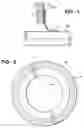
FIG. 2 is a plan view of a PTFE seal element of the seal assembly of FIG. 1; and
FIG. 3 is a process flow diagram according to one presently preferred aspect of the invention.
DETAILED DESCRIPTION OF PRESENTLY PREFERRED EMBODIMENTS
Referring in more detail to the drawings, FIG. 1 illustrates a rotary shaft seal assembly 10 constructed in accordance with one presently preferred aspect of the invention. The assembly 10 has a rigid annular carrier 12, preferably manufactured from metal, e.g. steel, configured for attachment to a machine component, such as a bearing ring or housing (not shown), for example. It is to be understood that the carrier 12 can be configured in any suitable manner. The assembly 10 further has an annular elastomer 14 attached thereto, such as in a molding process or by way of a suitable adhesive, and an annular PTFE seal element 16 attached to the elastomer 14. The PTFE seal element 16 extends radially inwardly from the carrier 12 to provide a seal lip 18 for dynamic sealing engagement with a shaft 20 rotating relative to the seal element 16.
In accordance with one aspect of the invention, and as diagrammed in FIG. 3, the PTFE seal element 16 is constructed by cutting a desired width disc from a PTFE billet, such as a tubular billet of desired diameter. The cutting operation can be performed using any suitable cutting mechanism. As such, the disc preferably takes on the general size and shape of the finished seal element 16 upon being cut. As such, for the seal element 16, the disc is generally a symmetrical annular disc having opposite flat sides facing away from one another. It should be understood that the disc can be formed having any desired size and shape.
Then the PTFE disc or discs are further processed by placing them into a suitably sized vacuum chamber. The vacuum chamber has a pair or pairs of electrodes spaced from one another, wherein one of the electrodes is preferably provided as a support or carrier upon which the discs are placed. The supporting electrode can be constructed as a mesh of metal wire, e.g. screen. The size of the mesh can be varied as desired to provide the properties to the electrode. The disc, if symmetrical, can be placed with either of its surfaces or sides engaging the supporting electrode, and if non-symmetrical, can be placed with the desired surface or side engaging the supporting electrode.
Upon placing the discs of PTFE onto the supporting electrode within the vacuum chamber, the process continues by drawing a vacuum pressure within the vacuum chamber. The vacuum pressure is preferably drawn to about 1 mbar.
Next, the process continues by introducing a first selected process gas into the vacuum chamber, such as hydrogen, oxygen, argon, ammonia, helium, nitrogen or water vapor. Upon the first process gas being introduced into the chamber, the process continues by applying a high frequency signal, such as about 40 kHz, 13.56 MHz, or 2.45 GHz, for example, to the electrodes for a predetermined period of time and producing a discharge plasma from the process gas between the electrodes. The high frequency signal is preferably applied for about 10 to 60 minutes, though the time period could be different depending on the size of the PTFE disc and the etching and chemical modification of the surface desired. The discharge plasma alters the surface of the PTFE disc by etching and chemically modifying the portion of the PTFE disc exposed to the plasma, such as shown generally at 22 in FIGS. 1 and 2. As such, the portion of the PTFE disc in contact with the wire mesh, or first side of the disc, is not etched to the extent that the opposite second side is etched, but the etching is sufficient for the application.
The next step in the process includes purging the vacuum chamber with a second selected process gas, such as nitrogen, and restoring the vacuum chamber to an atmospheric pressure.
Upon the vacuum chamber being purged, the process then involves rinsing the etched and chemically modified surface of the disc. The rinsing can be performed in a bath or spraying process, with the rinsing solution being provided as a mild acid solution such as dilute acetic acid.
After the rinsing step, the process preferably includes applying an adhesion promoter to the etched and chemically modified surface. The adhesion promoter can be provided as a silane or phenolic adhesive. The adhesion promoter can be applied in a spraying process or any other suitable process.
Lastly, the seal element is attached to the carrier. The seal element is oriented with the preferentially etched and chemically modified surface facing the carrier and an elastomer is then molded between the carrier and etched and chemically modified surface of the seal element. The molding process includes typical molding processes used in molding elastomers, such as an injection molding process, for example. Accordingly, the attaching process that attaches the seal element to the carrier does not require use of caustic chemicals or other potentially harmful process.
Obviously, many modifications and variations of the present invention are possible in light of the above teachings. It is, therefore, to be understood that within the scope of the appended claims, the invention may be practiced otherwise than as specifically described.
Claims
What is claimed is:1. A method of fabricating a PTFE seal element of a rotary shaft seal assembly, comprising:
providing a PTFE seal element having opposite first and second surfaces;
providing a vacuum chamber having electrodes therein;
placing the first surface of the PTFE seal element on one of the electrodes;
drawing a vacuum pressure in the vacuum chamber;
introducing a first selected process gas into the vacuum chamber;
applying a high frequency signal to the electrodes for a predetermined period of time and producing a discharge plasma from the process gas between the electrodes, the discharge plasma etching and chemically modifying the second surface of the PTFE seal element;
purging the vacuum chamber with a second selected process gas and restoring the vacuum chamber to an atmospheric pressure;
rinsing the second surface in a rinse solution; and
applying an adhesion promoter to the second surface.
2. The method of claim 1 further including using silane or a phenolic adhesive for the adhesion promoter.
3. The method of claim 1 further including using an acidic solution for the rinse solution.
4. The method of claim 1 further including providing the first selected process gas from the group consisting of hydrogen, oxygen, argon, ammonia, helium, nitrogen and water vapor.
5. The method of claim 1 further including providing the second selected process gas as nitrogen.
6. The method of claim 1 further including using a wire mesh tray as said one of the electrodes.
7. The method of claim 1 further including applying the high frequency signal to the electrodes for about 10 to 60 minutes.
8. A method of fabricating a rotary shaft seal assembly, comprising:
providing a rigid annular carrier;
providing an annular PTFE seal element having opposite first and second surfaces;
providing a vacuum chamber having electrodes therein;
placing the first surface of the PTFE seal element on one of the electrodes;
drawing a vacuum pressure in the vacuum chamber;
introducing a first selected process gas into the vacuum chamber;
applying a high frequency signal to the electrodes for a predetermined period of time and producing a discharge plasma from the process gas between the electrodes, the discharge plasma etching and chemically modifying at least a portion of the second surface of the PTFE seal element;
purging the vacuum chamber with a second selected process gas and restoring the vacuum chamber to an atmospheric pressure;
rinsing the second surface;
applying an adhesion promoter to the second surface; and
attaching the second surface to the carrier by molding an elastomer between the second surface and the carrier.
9. The method of claim 8 further including using an acidic solution for the rinse solution.
10. The method of claim 9 further including using silane for the adhesion promoter.
11. The method of claim 8 further including providing the first selected process gas from the group consisting of hydrogen, oxygen, argon, ammonia, helium, nitrogen and water vapor.
12. The method of claim 11 further including providing the second selected process gas as nitrogen.
13. The method of claim 8 further including using a wire mesh tray as said one of the electrodes.
14. The method of claim 8 further including applying the high frequency signal to the electrodes for about 10 to 60 minutes.
Images & Drawings included:

Sources:
- United States Patent and Trademark Office - verify current appl. status at the USPTO↗
Recent applications in this class:
- » 20240035573 2024-02-01
SEALING DEVICE - » 20220381347 2022-12-01
Seal assembly for rotatable shaft having ventilated dust seal with debris-blocking filter - » 20220316595 2022-10-06
Axial seal assembly with hinged lip - » 20220299114 2022-09-22
LEATHER FLANGE FOR A BIDIRECTIONAL SEAL ASSEMBLY - » 20220282791 2022-09-08
SEAL RING - » 20210277998 2021-09-09
Device for Sealing an Object - » 20210215252 2021-07-15
Seal structure for spool-type switching valve, and said spool-type switching valve - » 20190085979 2019-03-21
Dynamic sealing device - » 20190017602 2019-01-17
Sealing device, notably with regard to contamination by external agents - » 20170335968 2017-11-23
Seal device
Recent applications for this Assignee:
- » 20160312891 2016-10-27
Coated sliding element - » 20160252046 2016-09-01
Cylinder head gasket - » 20160138714 2016-05-19
Low tension piston rings and method for manufacturing the same - » 20160047474 2016-02-18
Shaft seal assembly with exclusion pump dust lip - » 20150337959 2015-11-26
PISTON WITH KEYSTONE SECOND RING GROOVE FOR HIGH TEMPERATURE INTERNAL COMBUSTION ENGINES - » 20150285378 2015-10-08
High modulus wear resistant gray cast iron for piston ring applications - » 20150226153 2015-08-13
CYLINDER HEAD GASKET FOR HIGH LOAD AND MOTION APPLICATIONS - » 20150226152 2015-08-13
Cylinder head gasket with compression control features - » 20150091433 2015-04-02
Spark plug having improved ground electrode orientation and method of forming - » 20150078030 2015-03-19
Optical coupler for vehicle lighting systems