Fuel storage system and method for detecting a gas pressure therein
US20100206887A1
2010-08-19
12/388,708
2009-02-19
✅ Patent granted
US 9,383,281 B2
2016-07-05
-
-
Huy Q Phan | Temilade Rhodes-Vivour
Damian Porcari | Brooks Kushman P.C.
2034-07-14
Abstract:
A fuel storage system includes a storage vessel including a dielectric liner, a voltage sensor formed by a pair of plates disposed on opposing surfaces of the liner, and a controller configured to determine a gas pressure in the storage vessel based on voltages measured by the sensor.
Inventors:
- Shahid Ahmed Siddiqui 9 🇺🇸 Northville, MI, United States
- Hasdi R. Hashim 14 🇺🇸 Ann Arbor, MI, United States
Assignee:
- FORD MOTOR COMPANY 800 🇺🇸 Dearborn, MI, United States
Applicant:
Interested in similar patents?
Get notified when new applications in this technology area are published.
Classification:
Y02E60/32 » CPC further
Enabling technologies; Technologies with a potential or indirect contribution to GHG emissions mitigation; Hydrogen technology Hydrogen storage
Y02E60/32 » CPC further
Enabling technologies; Technologies with a potential or indirect contribution to GHG emissions mitigation; Hydrogen technology Hydrogen storage
F17C1/00 IPC
Pressure vessels, e.g. gas cylinder, gas tank, replaceable cartridge
G01L9/12 IPC
Measuring steady of quasi-steady pressure of fluid or fluent solid material by electric or magnetic pressure-sensitive elements ; Transmitting or indicating the displacement of mechanical pressure-sensitive elements, used to measure the steady or quasi-steady pressure of a fluid or fluent solid material, by electric or magnetic means by making use of variations in capacitance, i.e. electric circuits therefor
G01L9/0005 » CPC main
Measuring steady of quasi-steady pressure of fluid or fluent solid material by electric or magnetic pressure-sensitive elements ; Transmitting or indicating the displacement of mechanical pressure-sensitive elements, used to measure the steady or quasi-steady pressure of a fluid or fluent solid material, by electric or magnetic means; Transmitting or indicating the displacement of elastically deformable gauges by electric, electro-mechanical, magnetic or electro-magnetic means using variations in capacitance
F17C13/025 » CPC further
Details of vessels or of the filling or discharging of vessels; Special adaptations of indicating, measuring, or monitoring equipment having the pressure as the parameter
G01M3/186 » CPC further
Investigating fluid-tightness of structures by using fluid or vacuum by detecting the presence of fluid at the leakage point using electric detection means for pipes, cables or tubes; for pipe joints or seals; for valves; for welds; for containers, e.g. radiators for containers, e.g. radiators
F17C2203/0604 » CPC further
Vessel construction, in particular walls or details thereof; Materials for walls or layers thereof; Properties or structures of walls or their materials; Wall structures; Special features thereof Liners
F17C2203/066 » CPC further
Vessel construction, in particular walls or details thereof; Materials for walls or layers thereof; Properties or structures of walls or their materials; Materials for walls or layers thereof; Synthetics Plastics
F17C2203/0619 » CPC further
Vessel construction, in particular walls or details thereof; Materials for walls or layers thereof; Properties or structures of walls or their materials; Wall structures; Special features thereof; Wall structures; Single wall with two layers
F17C2203/0663 » CPC further
Vessel construction, in particular walls or details thereof; Materials for walls or layers thereof; Properties or structures of walls or their materials; Materials for walls or layers thereof; Synthetics in form of fibers or filaments
F17C2205/0326 » CPC further
Vessel construction, in particular mounting arrangements, attachments or identifications means; Fluid connections, filters, valves, closure means or other attachments; Fittings, valves, filters, or components in connection with the gas storage device; Valves electrically actuated
F17C2205/0391 » CPC further
Vessel construction, in particular mounting arrangements, attachments or identifications means; Fluid connections, filters, valves, closure means or other attachments; Arrangement of valves, regulators, filters inside the pressure vessel
F17C2221/012 » CPC further
Handled fluid, in particular type of fluid; Pure fluids Hydrogen
F17C2223/0123 » CPC further
Handled fluid before transfer, i.e. state of fluid when stored in the vessel or before transfer from the vessel characterised by the phase; Single phase gaseous, e.g. CNG, GNC
F17C2223/036 » CPC further
Handled fluid before transfer, i.e. state of fluid when stored in the vessel or before transfer from the vessel characterised by the pressure level Very high pressure (>80 bar)
F17C2250/032 » CPC further
Accessories; Control means; Indicating, measuring or monitoring of parameters; Control means using computers
F17C2250/043 » CPC further
Accessories; Control means; Indicating, measuring or monitoring of parameters; Indicating or measuring of parameters as input values; Parameters indicated or measured Pressure
F17C2250/0439 » CPC further
Accessories; Control means; Indicating, measuring or monitoring of parameters; Indicating or measuring of parameters as input values; Parameters indicated or measured Temperature
F17C2250/0495 » CPC further
Accessories; Control means; Indicating, measuring or monitoring of parameters; Indicating or measuring of parameters as input values; Indicating or measuring characterised by the location the indicated parameter is a converted measured parameter
F17C2270/0168 » CPC further
Applications for fluid transport or storage on the road by vehicles
H01L2221/00 » CPC further
Processes or apparatus adapted for the manufacture or treatment of semiconductor or solid state devices or of parts thereof covered by
G01R1/00 » CPC further
Details of instruments or arrangements of the types included in groups - and
H02J1/00 » CPC further
Circuit arrangements for dc mains or dc distribution networks
G01L21/30 IPC
Vacuum gauges by making use of ionisation effects
G01L9/00 IPC
Measuring steady of quasi-steady pressure of fluid or fluent solid material by electric or magnetic pressure-sensitive elements ; Transmitting or indicating the displacement of mechanical pressure-sensitive elements, used to measure the steady or quasi-steady pressure of a fluid or fluent solid material, by electric or magnetic means
G01M3/18 IPC
Investigating fluid-tightness of structures by using fluid or vacuum by detecting the presence of fluid at the leakage point using electric detection means for pipes, cables or tubes; for pipe joints or seals; for valves; for welds; for containers, e.g. radiators
F17C13/02 IPC
Details of vessels or of the filling or discharging of vessels Special adaptations of indicating, measuring, or monitoring equipment
F17C2250/0491 » CPC further
Accessories; Control means; Indicating, measuring or monitoring of parameters; Indicating or measuring of parameters as input values; Indicating or measuring characterised by the location Parameters measured at or inside the vessel
Description
BACKGROUND
A capacitor is a passive electrical component that can store energy in an electric field between a pair of conductors. The process of storing energy in the capacitor is known as “charging,” and involves electric charges of equal magnitude, but opposite polarity, building up on each conductor. A capacitor's ability to store charge is measured by its capacitance in units of farads.
Capacitors are often used in electric and electronic circuits as energy-storage devices. They can also be used to differentiate between high-frequency and low-frequency signals. Practical capacitors have series resistance, internal leakage of charge, series inductance and other non-ideal properties not found in a theoretical, ideal, capacitor.
Some capacitors include two conductive electrodes, or plates, separated by a dielectric, which prevents charge from moving directly between the plates. Charge may, however, move from one plate to the other through an external circuit, such as a battery connected between terminals of the plates. When any external connection is removed, the charge on the plates persists. The separated charges attract each other, and an electric field is present between the plates.
An example capacitor may include two wide, flat, parallel plates separated by a thin dielectric layer. Assuming the area of the plates, A, is much greater than their separation, d, the instantaneous electric field between the plates, E(t), is generally the same at any location away from the plate edges. If the instantaneous charge on a plate, −q(t), is spread evenly, then
E(t)=q(t)/εA (1)
where ε is the permittivity of the dielectric. The voltage, v(t), between the plates is given by
v(t)=∫odE(t)dz=q(t)d/εA (2)
where z is a position between the plates.
A capacitor's ability to store charge is measured by its capacitance, C, which is the ratio of the amount of charge stored on each plate, q, to the voltage, v:
C=q/v (3)
or, substituting (2) into (3):
C=εA/d. (4)
In SI units, a capacitor has a capacitance of one farad when one coulomb of charge stored on each plate causes a voltage difference of one volt between its plates. Capacitance, however, is usually expressed in microfarads (μF), nanofarads (nF) or picofarads (pF). In general, capacitance is greater in devices with large plate areas, separated by small distances. When a dielectric is present between two charged plates, its molecules become polarized and reduce the internal electric field and hence the voltage. This allows the capacitor to store more charge for a given voltage: a dielectric increases the capacitance of a capacitor by an amount proportional to the dielectric constant of the material.
SUMMARY
A fuel storage system may include a storage vessel including a dielectric liner, a voltage sensor formed by a pair of plates disposed on opposing surfaces of the liner, and a controller configured to determine a gas pressure in the storage vessel based on voltages measured by the sensor.
A fuel storage system may include a storage vessel including a dielectric liner, a first sensor formed by a first pair of plates disposed on opposing surfaces of the liner, and a second sensor formed by (i) a second pair of plates disposed on opposing surfaces of the liner and (ii) a thermistor disposed within the storage vessel and electrically connected with one of the second pair of plates. The system may also include a controller configured to determine a gas temperature in the storage vessel based on respective voltages across the first and second sensors.
A method for detecting a gas pressure within a storage vessel having a dielectric liner may include measuring a voltage over time across a sensor formed by a pair of metal plates disposed on opposing surfaces of the liner, and determining a gas pressure within the storage vessel based on the measured voltage across the sensor.
While example embodiments in accordance with the invention are illustrated and disclosed, such disclosure should not be construed to limit the invention. It is anticipated that various modifications and alternative designs may be made without departing from the scope of the invention.
BRIEF DESCRIPTION OF THE DRAWINGS
FIG. 1 is a side view, in cross-section, of an example fuel storage system.
FIG. 2 is an end view, in cross-section, of another example fuel storage system.
FIG. 3 is a schematic view of an embodiment of the fuel storage system of FIG. 2.
DETAILED DESCRIPTION
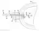
Referring now to FIG. 1, an automotive fuel storage system includes a pressurized tank 10 and a valve 12 threadedly engaged with the tank 10. The valve 12 provides a passageway 14 for hydrogen gas to be provided to the tank 10. An O-ring 13 provides a seal between the valve 12 and the tank 10.
A moveable element 16, e.g., plunger, of a solenoid 18 may be positioned by the solenoid 18 to restrict or block the flow of hydrogen gas through the passageway 14. As illustrated in FIG. 1, the moveable element 16 is in the open position, thus allowing hydrogen to flow through the passageway 14. In the closed position (not shown), the moveable element 16 extends into the passageway 14.
The solenoid 18 receives control signals from a vehicle controller (not shown) via a pair of solenoid control wires 20. The solenoid control wires 20 pass through a pressure seal 22 and terminate at an electrical connector 24. The electrical connector 24 is attached with a mating electrical connector 26 of a wiring harness 27 electrically connected with the vehicle controller.
A temperature sensor 28 is disposed within the tank 10 and may be attached to the solenoid 18 via a tie-strap 29. The sensor 28 provides signals indicative of a temperature of the hydrogen within the tank 10 to the vehicle controller via a pair of sensor wires 30. The sensor wires 30 also pass through the seal 22 within the valve 12 and terminate at the electrical connector 24. A pressure sensor (not shown) may be similarly situated.
Referring now to FIG. 2, an embodiment of a fuel storage system 32 includes a storage tank 34, valve 36, and sensors 38, 40. The valve 36 is electrically grounded (e.g., grounded to a chassis of a vehicle). The storage tank 34 of FIG. 2 includes a dielectric liner 42, e.g., high density polyethylene (HDPE), and a wrap 44, e.g., carbon fiber. As known to those of ordinary skill, the storage tank 34 may store hydrogen for use with an automotive fuel cell system. The storage system 32 also includes first and second circuits 46, 48 and a controller 50 in communication with the circuits 46, 48. In other embodiments, the circuits 46, 48 may be integrated with the controller 50. Other configurations are also possible. The circuits 46, 48 and controller 50 will be discussed in more detail below.
The sensor 38 includes a pair of metal plates 52, 54 positioned on opposing sides of the liner 42. The plate 52 is grounded (e.g., grounded to the chassis of the vehicle) via the valve 36. The sensor 40 includes a pair of metal plates 56, 58 positioned on opposing sides of the liner 42 and a thermistor 60 electrically connected between the valve 36 and plate 56. The plate 56 is grounded (e.g., grounded to the chassis of the vehicle) via the thermistor 60 and valve 36. In the embodiment of FIG. 2, the metal plates 52, 54, 56, 58 are adhered with the liner 42. Any suitable attachment method, however, may be used.
As apparent to those of ordinary skill, the metal plates 52, 54 as well as the metal plates 56, 58 form capacitors. As explained below, the capacitance of sensor 38 may be used to determine the pressure in the storage tank 34, and the resistance of the thermistor 60 may be used to determine the temperature in the storage tank 34.
Referring now to FIG. 3, the first circuit 46 may include a resistor 62 (having a known resistance) and an inverting Schmitt trigger 64. Of course, any suitable circuit configuration, e.g., Op-amp, voltage comparator, analog digital converter, etc., may be used. As apparent to those of ordinary skill, the sensor 38 and resistor 62 form an RC circuit.
Initially, the output of the trigger 64 applies a HIGH step response to this RC circuit while the input of the trigger 64 senses the voltage across the sensor 38. Once the voltage rises above the ‘upper’ threshold of the trigger 64, the output of the trigger 64 will apply a LOW step response. Once the voltage falls below the ‘lower’ threshold, the output is HIGH again. The periodic signal generated by this circuit is detected by the controller 50 to determine the capacitance, C38, of the sensor 38.
As known to those of ordinary skill, the step response of the above RC circuit is related to the resistance, R62, of the resistor 62 and the capacitance, C38, of the sensor 38. Assuming, for example, a HIGH step response of 5 Volts, the voltage across the sensor 40 over time, t, is give by:
v 38 ( t ) = 5 · ( 1 - - t / R 62 C 38 ) ( 5 )
The time constant, τ1, derived from this step response is the time for the voltage across the sensor 38 to reach approximately 63% of its final (asymptotic) value:
τ1=R62C38 (6)
The period detected by the controller 50 is proportional to this time constant, τ1. The controller 50 may thus find the capacitance, C38, of the sensor 38 as it is the only unknown. (The capacitance will increase as the pressure within the tank 34 increases.)
From (4), the capacitance, C38, of the sensor 38 is related to the area, A38, of the plates 52, 54 in contact with the liner 42 and the thickness, t42, of the liner 42:
C38=εA38/t42 (7)
where ε is the permittivity of the liner 42. The controller 50 may thus find the thickness, t42, of the liner 42 between the plates 52, 54 as it is the only unknown.
The controller 50 may then apply known analytical techniques or access a look-up table (generated, for example, via testing or simulation) relating the thickness of the liner 42 to the pressure within the storage tank 34 to find the pressure within the storage tank 34.
The second circuit 48 may include a resistor 66 (having a known resistance) and an inverting Schmitt trigger 68. Of course, any suitable circuit configuration may be used. Similar to the sensor 38, the sensor 40 and resistor 66 form another RC circuit.
The periodic signal generated by this circuit may be detected by the controller 50 to determine the resistance, R60, of the thermistor 60. This period, however, is also affected by the capacitance, C40, of the sensor 40. By constructing sensor 38 and sensor 40 such that their capacitance is generally the same (e.g. the plates 52, 54 and 56, 58 are of approximate equal size), the differences in the step response of the first RC circuit (formed by sensor 38 and resistor 62) and the step response of the second RC circuit (formed by the sensor 40 and the resistor 66) may thus be used to determine the temperature within the tank 34.
As known to those of ordinary skill, the step response of the second RC circuit is related to the resistance, R66, of the resistor 66, the capacitance, C40, of the sensor 40, and the resistance, R60, of the thermistor 60 (part of sensor 40). Assuming, for example, a HIGH step response of 5 Volts, the voltage across sensor 40 over time, t, is given by:
v 40 ( t ) = 5 · ( 1 - R 66 R 66 + R 60 - t / ( R 66 + R 60 ) C 40 ) ( 8 )
Assuming that R60≦R66, the time constant, τ2, derived from this step response is the time for the voltage across the sensor 40 to reach approximately 63% of its final (asymptotic) value:
τ2=[1+ln(R66)−ln(R66+R60)](R66+R60)C40 (9)
The period detected by the controller 50 is proportional to this time constant, τ2. By assuming that the capacitance, C40, of the sensor 40 is generally the same as the capacitance, C38, of the sensor 38 (that is separately determined), the controller 50 may thus find the resistance, R60, of the thermistor 60 as it is the only unknown. The controller 50 may then, for example, access a standard look-up table relating the resistance R60 of the thermistor 60 to the temperature within the tank 60 to find the temperature within the tank 60.
As apparent to those of ordinary skill, sensor wires passing from inside the storage tank 34 to outside the storage tank 34 are not required (in contrast, for example, to the sensor wires 30 associated with the temperature sensor 28 illustrated in FIG. 1). As a result, the fuel storage system 32 may be less likely to leak relative to the fuel storage 10 illustrated in FIG. 1.
While embodiments of the invention have been illustrated and described, it is not intended that these embodiments illustrate and describe all possible forms of the invention. The words used in the specification are words of description rather than limitation, and it is understood that various changes may be made without departing from the spirit and scope of the invention.
Claims
What is claimed:1. A fuel storage system comprising:
a storage vessel including a dielectric liner;
a voltage sensor formed by a pair of plates disposed on opposing surfaces of the liner; and
a controller configured to determine a gas pressure in the storage vessel based on voltages measured by the sensor.
2. The system of claim 1 wherein the controller is further configured to determine a capacitance of the sensor based on the voltages measured by the sensor.
3. The system of claim 2 wherein the controller is further configured to determine a distance between the plates based on the capacitance of the sensor.
4. The system of claim 1 wherein one of the plates is electrically grounded.
5. The system of claim 1 wherein the plates are electrically conductive.
6. A fuel storage system comprising:
a storage vessel including a dielectric liner;
a first sensor formed by a first pair of plates disposed on opposing surfaces of the liner;
a second sensor formed by (i) a second pair of plates disposed on opposing surfaces of the liner and (ii) a thermistor disposed within the storage vessel and electrically connected with one of the second pair of plates; and
a controller configured to determine a gas temperature in the storage vessel based on respective voltages across the first and second sensors.
7. The system of claim 6 wherein the controller is further configured to determine a capacitance of the first sensor based on the voltage across the first sensor.
8. The system of claim 7 wherein the controller is further configured to determine a distance between the first pair of plates based on the capacitance of the first sensor.
9. The system of claim 8 wherein the controller is further configured to determine a gas pressure within the storage vessel based on the distance between the first pair of plates.
10. The system of claim 6 wherein the controller is further configured to determine a resistance of the thermistor based on the voltage across the second sensor.
11. The system of claim 6 wherein one of the first pair of plates is electrically grounded.
12. The system of claim 6 wherein the one of the second pair of plates is electrically grounded via the thermistor.
13. The system of claim 6 wherein the first pair of plates are electrically conductive.
14. The system of claim 6 wherein the second pair of plates are electrically conductive.
15. A method for detecting a gas pressure within a storage vessel having a dielectric liner comprising:
measuring a voltage over time across a sensor formed by a pair of metal plates disposed on opposing surfaces of the liner; and
determining a gas pressure within the storage vessel based on the measured voltage across the sensor.
16. The method of claim 15 wherein determining a gas pressure within the storage vessel based on the measured voltage across the sensor includes determining a capacitance of the sensor based on the measured voltage across the sensor.
17. The method of claim 16 wherein determining a gas pressure within the storage vessel based on the measured voltage across the sensor includes determining a thickness of the dielectric liner based on the capacitance of the sensor.
Images & Drawings included:


Sources:
- United States Patent and Trademark Office - verify current appl. status at the USPTO↗
Recent applications in this class:
- » 20210088397 2021-03-25
Sensor mat for an area sensor system, area sensor system, and method for producing a sensor mat - » 20200149987 2020-05-14
Method of Fabricating Flexible Pressure Sensors - » 20200103298 2020-04-02
Sensing apparatus - » 20170199095 2017-07-13
Foam pressure sensor - » 20150260593 2015-09-17
MIRCO-ELECTRO-MECHANICAL SYSTEM PRESSURE SENSOR AND MANUFACTURING METHOD THEREOF - » 20130118265 2013-05-16
MEMS capacitive pressure sensor, operating method and manufacturing method - » 20110248363 2011-10-13
Physical quantity detection device and method for manufacturing the same
Recent applications for this Assignee:
- » 20250224311 2025-07-10
METHOD OF TESTING VEHICLE CLEAR VISION - » 20250091530 2025-03-20
TOOL FOR INSTALLING HEADLINER IN A VEHICLE AND METHOD OF INSTALLING A HEADLINER IN A VEHICLE - » 20250010310 2025-01-09
SYSTEM AND METHOD FOR MONITORING OPERATION OF METAL SCRAP SHREDDER - » 20240425129 2024-12-26
THREADLESS POSITIONING FASTENER, PIN, AND RETAINER, AND RELATED ASSEMBLIES AND METHODS - » 20240424725 2024-12-26
THERMOFORMING PROCESS WITH A REFORMABLE MOLD - » 20240367693 2024-11-07
HANGING TROLLEY SYSTEM WITH BRAKE - » 20240307943 2024-09-19
STAMPING TOOL WITH A SUB PAD WITHIN A FORMING STEEL AND METHOD OF FORMING A PANEL FROM A SHEET METAL WORKPIECE - » 20240293856 2024-09-05
SYSTEMS AND METHODS FOR MONITORING OBSTRUCTIONS IN A CONDUIT OF A STAMPING ENVIRONMENT - » 20240290535 2024-08-29
COIL ASSEMBLY AND METHOD OF MANUFACTURING SAME - » 20240280125 2024-08-22
RETAINER FOR SECURING COMPONENT TO STRUCTURE